

Page 1

INSTALLATION INFORMATION FOR GC600, GC9002, CG901 SERIES* GAS COOKTOPS
NEW ZEALAND,
AUSTRALIA and SINGAPORE
IMPORTANT INFORMATION
Read the instructions before installing or using this
product.
Please make this information available to the person
responsible for installing this cooktop as soon as possible,
it could reduce your installation cost.
These products are registered:
in New Zealand at www.ess.govt.nz and
in Australia with AGA at www.gas.asn.au.
CAUTION
In order to avoid a hazard these products must be installed according
to these instructions for installation.
Please follow installation information carefully. If in doubt consult your
local building regulations, local gas authority codes and electrical
regulations.
Failure to install the appliance correctly could invalidate any warranty
or liability claims and lead to prosecution.
The product is to be installed only by a person aurthorised to
work on gas installations.
WARNINGS
This appliance shall be installed in accordance with the installation
requirements of the local gas authority or the appropriate installation
code issued by the A.L.P.G.A. and A.G.A. (Reference Code AGA 601),
or the Building Authorities requirements.
Particular attention shall be given to the relevant requirements
regarding ventilation.
Take care of sharp edges when handling stainless steel products.
When this product is installed it shall not be used as a space heater,
especially if installed in boats or caravans.
No combustible material or products should be placed on this product
at any time.
Do not spray aerosols in the vicinity of this product while it is in
operation.
This product should not be sealed into the bench with silicon or glue.
This will make future servicing difficult. Fisher & Paykel will not be
liable for costs associated with releasing such a product, nor for
repairing damage that may be incurred in doing this.
BEFORE YOU START
DO Prior to installation, ensure that the local distribution conditions
(nature of gas and pressure) and the adjustment of the product
are compatible.
DO Ensure a suitable disconnection switch is incorporated in the
permanent wiring, positioned to comply with the Local Wiring
Rules and Regulations.
DO Ensure the benchtop is square and level and ensure no structural
members interfere with space requirements.
DO Ensure that there is a 3 pin socket-outlet within reach of the
cooktop cable (900mm from rear right of product), this should be
accessible after installation. The mains cable should not touch
any hot metal parts.
DO Make the benchtop of a heat resistant material.
CURRENT INFORMATION
Current Installation Instructions, Product dimensions and
specifications are available on the Fisher & Paykel web site.
www.fisherpaykel.com
*Includes Quantum Models
Part No. 530451 D February 2003
Page 2
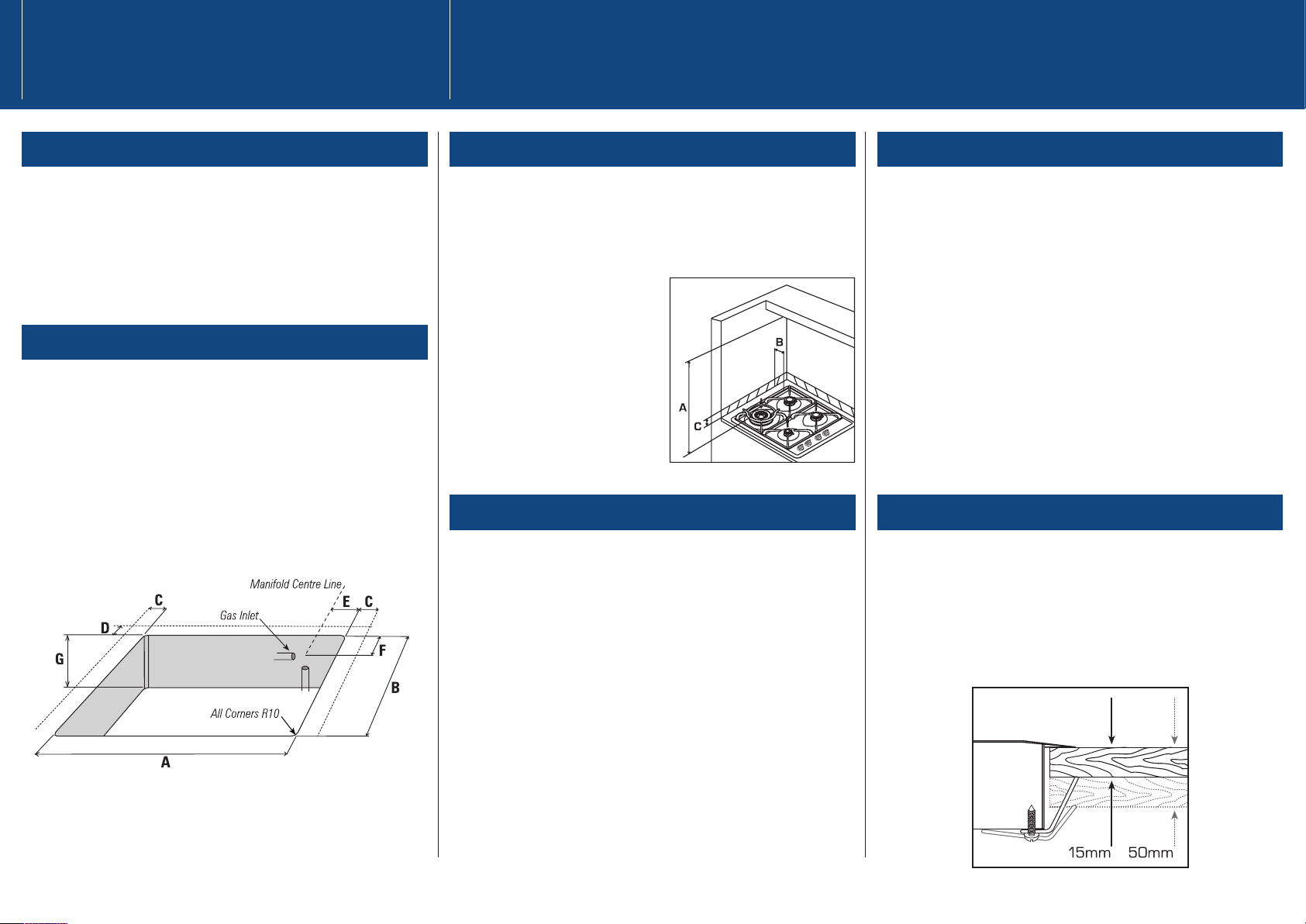
PRODUCT DIMENSIONS
GC600 GC9002 CG901M
Width 578mm 914mm 914mm
Depth 511mm 533mm 546mm
Height 40mm 40mm 76mm
Note Height measurement below bench surface.
CUTOUT DIMENSIONS
GC600 GC9002 CG901M
A Width 560-564mm 846-882mm 860-895mm
B Depth 485-495mm 478-501mm 486-524mm
C Side Clearances* 140mm 140mm 118mm
D Rear Clearance* 100mm 100mm 120mm
E Entry from Side 50mm 50mm 25mm
F Entry from Back 30mm 30mm 25mm
G Clearance Below* 60mm 60mm 81mm
Bench
*Minimum clearance for cutout to combustible surface.
RANGEHOOD CLEARANCE (Dimension A)
[See A.G.A. 601 5.12.1.6]
Dimension A (Measured from the plane of the pan supports to
Rangehood) should not be less than 650mm.
Any other downward facing combustible surface less than 600mm
above the highest part of the hob
shall be protected for the full
width and depth of the cooking
surface area.
However, in no case should this
clearance to any surface be less
than 450mm.
SIDE CLEARANCE (Dimensions B & C)
Where Dimension B, measured from the periphery of the nearest
burner to any vertical combustible surface, is less than 200mm, the
surface shall be protected in accordance with Clause 5.12.1.2 to a
Height C of not less than 150mm above the hob for the full
dimension (width or depth) of the cooking surface area.
Do use easy-to-clean finishes for the wall surfaces surrounding the
cooktop to aid removal of any cooking stains resulting from use of the
cooktop.
A.G.A. Clause 5.12.1.2.
A.G.A. Clause 5.12.1.2. Protection of a Combustible Surface
Near a Cooking Appliance.
The protection required by clause 5.12.1.1. shall ensure the surface
temperature of the combustible surface does not exceed 50°C above
ambient.
Note The fixing of 5mm thick ceramic tiles to the surface or
attaching fire resistant materials to the surface and covering with
sheet metal with a minimum thickness of 1.4mm would satisfy this
requirement.
CLAMPING DOWN THE COOKTOP/HOB
Place the cooktop into the cutout and tighten it with the supplied
clamps. DO NOT OVER TIGHTEN.
The clamps will cope with bench thickness 15-50mm
(see diagram) when used in the two orientations.
Dimensions Clearances
When used with a flexible hose, the connector on the wall should be
between 800mm to 850mm above the floor and in the region outside
the width of the appliance to a distance of 250mm. This should be
accessable with the appliance installed.
Page 3

GAS SUPPLY CONNECTION
The product is supplied set up for Natural Gas. This cooktop is
suitable for installation with Natural Gas, or LP Gas. Refer to table for
the relevant pressures and appropriate injector sizes.
- Gas connection to the product must use the elbow supplied. The
regulator will not seal if installed without it.
- Ensure the blue washer (supplied) is located between the
elbow and the product inlet. Failure to use this will cause
the product to leak.
AFTER INSTALLATION, MAKE SURE ALL CONNECTIONS ARE
GAS SOUND.
FLEXIBLE HOSES
Flexible hose assemblies should be AS/NZS 1869 Class B or
Class D certified.
Flexible hoses should not be exposed to temperatures exceeding
their certified value. They should not touch hot surfaces on the
cooktop or neighbouring products.
Flexible hoses should not be subject to abrasion, kinking or
permanent deformation.
FOR LP GAS MODELS
For LPG Models the gas supply for the appliance must be regulated to
a pressure of 2.72kPa (11" WG). See below for conversions.
FOR NATURAL GAS MODELS
For NG Models the gas supply is connected to the regulator which is
supplied loose with a built in test point - 1kPa (4" WG) and the inlet
connection of 1/2 " B.S.P. (male thread). Do not over tighten.
The test point pressure should be preset to 1.0 kPa with the wok and
semi - rapid burners operating at maximum.
GAS SUPPLY CONNECTION CHECK
To enable the gas supply to be readily shut off, the gas supply must
be connected with an isolating valve close to the product.
After installation and making all connections check thoroughly for
possible leaks.
1. Turn all control knobs on the unit to “off” position.
2. Open the valve on the gas supply.
3. Using a suitable leak testing solution (e.g. Rocol) check each gas
connection one at a time by brushing the solution over the connection.
4. The presence of bubbles will indicate a leak. Tighten the fitting and
recheck for leaks. Ensure the blue washer (supplied) is located
between elbow and manifold.
5. Turn on each gas valve and light each burner.
6. Check for a clear blue flame without yellow tipping. If burners
show any abnormalities, check that they are located properly and in
line with injector nipple. Check correct orifices are installed.
7. The operation of the appliance, including the ignition system, must
be tested before leaving.
If after following the instructions given, satisfactory performance
cannot be obtained, contact the local gas authority or your local
Approved Service Agent for advice and assistance.
GAS RATE SUMMARY
Your product is factory set for Natural Gas but may be converted to
LPG use. See overleaf. Refer to the chart below for ratings.
BURNERS Natural Gas LP Gas
Injector MJ/h Injector MJ/h
Orifice @1 kPa Orifice @2.75kPa
GC 9002 series
Semi-Rapid Burner
(LH & RH Rear) 1.3mm 7.9MJ/h 0.80mm 7.9MJ/h
Aux Burner (RH Front) 0.85mm 3.7MJ/h 0.55mm 4.1MJ/h
Fish Burner (Centre) 1.45mm 10MJ/h 0.85mm 10MJ/h
Wok Burner (LH Front) 1.8mm 15MJ/h 1.05mm 15MJ/h
GC 600 Series
Semi-Rapid Burner
(LH & RH Rear) 1.1mm 6.1MJ/h 0.70mm 6.4MJ/h
Aux Burner (RH Front) 0.85mm 3.7MJ/h 0.55mm 4.1MJ/h
Wok Burner (LH Front) 1.75mm 15MJ/h 1.05mm 15MJ/h
CG 901 M
Semi-Rapid Burner (LH Rear) 1.1mm 6.1MJ/h 0.7mm 6.4MJ/h
Simmer Burner (RH Front) 0.85mm 3.2MJ/h 0.55mm 3.2MJ/h
Rapid Burner
(LH Front, RH Rear) 1.3mm 7.9MJ/h 0.8mm 8.4MJ/h
Wok Burner (Centre) 1.8mm 15MJ/h 1.08mm 15MJ/h
The data plate information can be found in the duplicate data plate
which should be placed on an accessible surface adjacent to the
cooktop.
Gas Supply
Page 4

CONVERSION TO DIFFERENT GAS TYPE
Burners can be used with NG or LPG, provided that the injector
orifices appropriate for the gas delivered are installed.
To change the injector orifices, you will need a 7mm box spanner and
a 10mm ring spanner (CG901M only).
1. Turn off the main electrical supply. WARNING: Shock Hazard Inside.
2. Ensure all gas valves are turned off.
3. Remove all trivets and burner heads.
4. Pull off knobs.
5. Unscrew the nut securing the flame failure probe of the
mini-auxiliary burner.
6. Remove the 2 screws holding each burner (3 on the wok burner).
7. Partially lift the hob and unplug the electrode on the mini-auxiliary
burner to allow hob removal. Caution The edge can be sharp.
8. Unscrew the orifices and replace them with the correct ones.
(size numbers are stamped on the side, eg. 70= 0.70mm)
9. Reset the venturi position aligning the end
of the venturi tube with the edge of the slot
in the bracket below it. Outermost position
for LPG, innermost for NG (see figure right).
Some fine adjustment may be required for
local conditions.
10. To replace the CG901M hob, repeat steps 1-7 in reverse.
11. Reset the minimum setting (see next column).
The label supplied with the orifices should
be placed over the existing gas type label
to indicate the change.
MINIMUM SETTING OR TURN DOWN
This has been set at the factory for NG but can be checked after the
correct pressure has been reached.
To adjust the minimum setting you will need a Ø 2.5 x 45 screwdriver.
1. Remove the knob.
2. Ignite the burner and set the knob to its minimum position.
3. Rotate the turn down screw (down the hole in the valve spindle).
Rotate slowly until a minimum regular flame is achieved. (The flame
will diminish when the screw is turned clockwise and increase when
turned anti-clockwise).
4. When the setting is right check regulation by quickly rotating the
knob from the maximum to the minimum delivery position. The flame
must not go out.
5. Replace the knob.
Before you call for service or assistance...
Check the things you can do yourself.
Refer to your User Guide and check....
1. Your product is correctly installed.
2. You are familiar with its normal operation.
If after checking these points you still need assistance, please call
your Fisher & Paykel retailer who is trained to provide information on
your product, or if we can be of any further help, please contact our
Customer Care Centre.
NEW ZEALAND
P. O. Box 58732, Greenmount, Auckland.
Toll Free 0800 FP CARE (0800 37 2273)
Fax 09 273 0656
Email customer.care@fp.co.nz
AUSTRALIA
P. O. Box 798, Cleveland, QLD 4163.
Toll Free 1300 650 590
Tel 07 3826 9100
Fax 07 3826 9298
Email customer.care@fp.com.au
SINGAPORE
150Ubi Avenue 4, 02-00, Sunlight Building, Singapore 408825
Tel +65 5470100
Fax +65 5470123
Email customerservice@fisherpaykel.com.sg
Adjusting the Cooktop Customer Support
NG Venturi Position
LPG Venturi Position
CG901M only CG901M only
 Loading...