

Fisher & Paykel GC9002 Series, GC600 Series, CG901 Series Installation Information
INSTALLATION INFORMATION FOR GC600, GC9002, CG901 SERIES* GAS COOKTOPS
NEW ZEALAND,
AUSTRALIA and SINGAPORE
IMPORTANT INFORMATION
Read the instructions before installing or using this
product.
Please make this information available to the person
responsible for installing this cooktop as soon as possible,
it could reduce your installation cost.
These products are registered:
in New Zealand at www.ess.govt.nz and
in Australia with AGA at www.gas.asn.au.
CAUTION
In order to avoid a hazard these products must be installed according
to these instructions for installation.
Please follow installation information carefully. If in doubt consult your
local building regulations, local gas authority codes and electrical
regulations.
Failure to install the appliance correctly could invalidate any warranty
or liability claims and lead to prosecution.
The product is to be installed only by a person aurthorised to
work on gas installations.
WARNINGS
This appliance shall be installed in accordance with the installation
requirements of the local gas authority or the appropriate installation
code issued by the A.L.P.G.A. and A.G.A. (Reference Code AGA 601),
or the Building Authorities requirements.
Particular attention shall be given to the relevant requirements
regarding ventilation.
Take care of sharp edges when handling stainless steel products.
When this product is installed it shall not be used as a space heater,
especially if installed in boats or caravans.
No combustible material or products should be placed on this product
at any time.
Do not spray aerosols in the vicinity of this product while it is in
operation.
This product should not be sealed into the bench with silicon or glue.
This will make future servicing difficult. Fisher & Paykel will not be
liable for costs associated with releasing such a product, nor for
repairing damage that may be incurred in doing this.
BEFORE YOU START
DO Prior to installation, ensure that the local distribution conditions
(nature of gas and pressure) and the adjustment of the product
are compatible.
DO Ensure a suitable disconnection switch is incorporated in the
permanent wiring, positioned to comply with the Local Wiring
Rules and Regulations.
DO Ensure the benchtop is square and level and ensure no structural
members interfere with space requirements.
DO Ensure that there is a 3 pin socket-outlet within reach of the
cooktop cable (900mm from rear right of product), this should be
accessible after installation. The mains cable should not touch
any hot metal parts.
DO Make the benchtop of a heat resistant material.
CURRENT INFORMATION
Current Installation Instructions, Product dimensions and
specifications are available on the Fisher & Paykel web site.
www.fisherpaykel.com
*Includes Quantum Models
Part No. 530451 D February 2003
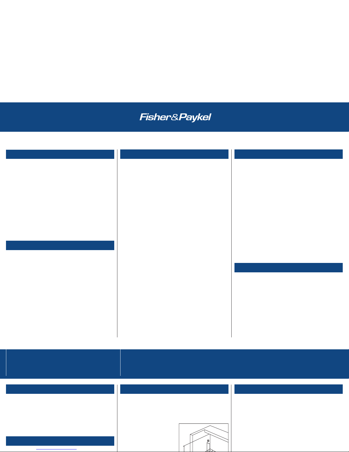
PRODUCT DIMENSIONS
GC600 GC9002 CG901M
Width 578mm 914mm 914mm
Depth 511mm 533mm 546mm
Height 40mm 40mm 76mm
Note Height measurement below bench surface.
CUTOUT DIMENSIONS
RANGEHOOD CLEARANCE (Dimension A)
[See A.G.A. 601 5.12.1.6]
Dimension A (Measured from the plane of the pan supports to
Rangehood) should not be less than 650mm.
Any other downward facing combustible surface less than 600mm
above the highest part of the hob
shall be protected for the full
width and depth of the cooking
surface area.
However, in no case should this
A.G.A. Clause 5.12.1.2.
A.G.A. Clause 5.12.1.2. Protection of a Combustible Surface
Near a Cooking Appliance.
The protection required by clause 5.12.1.1. shall ensure the surface
temperature of the combustible surface does not exceed 50°C above
ambient.
Note The fixing of 5mm thick ceramic tiles to the surface or
attaching fire resistant materials to the surface and covering with
sheet metal with a minimum thickness of 1.4mm would satisfy this
Dimensions Clearances
IMPORTANT INFORMATION
Read the instructions before installing or using this
product.
Please make this information available to the person
responsible for installing this cooktop as soon as possible,
it could reduce your installation cost.
These products are registered:
in New Zealand at www.ess.govt.nz and
in Australia with AGA at www.gas.asn.au.
CAUTION
In order to avoid a hazard these products must be installed according
to these instructions for installation.
Please follow installation information carefully. If in doubt consult your
local building regulations, local gas authority codes and electrical
regulations.
Failure to install the appliance correctly could invalidate any warranty
or liability claims and lead to prosecution.
The product is to be installed only by a person aurthorised to
work on gas installations.
WARNINGS
This appliance shall be installed in accordance with the installation
requirements of the local gas authority or the appropriate installation
code issued by the A.L.P.G.A. and A.G.A. (Reference Code AGA 601),
or the Building Authorities requirements.
Particular attention shall be given to the relevant requirements
regarding ventilation.
Take care of sharp edges when handling stainless steel products.
When this product is installed it shall not be used as a space heater,
especially if installed in boats or caravans.
No combustible material or products should be placed on this product
at any time.
Do not spray aerosols in the vicinity of this product while it is in
operation.
This product should not be sealed into the bench with silicon or glue.
This will make future servicing difficult. Fisher & Paykel will not be
liable for costs associated with releasing such a product, nor for
repairing damage that may be incurred in doing this.
BEFORE YOU START
DO Prior to installation, ensure that the local distribution conditions
(nature of gas and pressure) and the adjustment of the product
are compatible.
DO Ensure a suitable disconnection switch is incorporated in the
permanent wiring, positioned to comply with the Local Wiring
Rules and Regulations.
DO Ensure the benchtop is square and level and ensure no structural
members interfere with space requirements.
DO Ensure that there is a 3 pin socket-outlet within reach of the
cooktop cable (900mm from rear right of product), this should be
accessible after installation. The mains cable should not touch
any hot metal parts.
DO Make the benchtop of a heat resistant material.
CURRENT INFORMATION
Current Installation Instructions, Product dimensions and
specifications are available on the Fisher & Paykel web site.
www.fisherpaykel.com
*Includes Quantum Models
Part No. 530451 D February 2003
PRODUCT DIMENSIONS
GC600 GC9002 CG901M
Width 578mm 914mm 914mm
Depth 511mm 533mm 546mm
Height 40mm 40mm 76mm
Note Height measurement below bench surface.
CUTOUT DIMENSIONS
GC600 GC9002 CG901M
A Width 560-564mm 846-882mm 860-895mm
B Depth 485-495mm 478-501mm 486-524mm
C Side Clearances* 140mm 140mm 118mm
D Rear Clearance* 100mm 100mm 120mm
E Entry from Side 50mm 50mm 25mm
F Entry from Back 30mm 30mm 25mm
G Clearance Below* 60mm 60mm 81mm
Bench
*Minimum clearance for cutout to combustible surface.
RANGEHOOD CLEARANCE (Dimension A)
[See A.G.A. 601 5.12.1.6]
Dimension A (Measured from the plane of the pan supports to
Rangehood) should not be less than 650mm.
Any other downward facing combustible surface less than 600mm
above the highest part of the hob
shall be protected for the full
width and depth of the cooking
surface area.
However, in no case should this
clearance to any surface be less
than 450mm.
SIDE CLEARANCE (Dimensions B & C)
Where Dimension B, measured from the periphery of the nearest
burner to any vertical combustible surface, is less than 200mm, the
surface shall be protected in accordance with Clause 5.12.1.2 to a
Height C of not less than 150mm above the hob for the full
dimension (width or depth) of the cooking surface area.
Do use easy-to-clean finishes for the wall surfaces surrounding the
cooktop to aid removal of any cooking stains resulting from use of the
cooktop.
A.G.A. Clause 5.12.1.2.
A.G.A. Clause 5.12.1.2. Protection of a Combustible Surface
Near a Cooking Appliance.
The protection required by clause 5.12.1.1. shall ensure the surface
temperature of the combustible surface does not exceed 50°C above
ambient.
Note The fixing of 5mm thick ceramic tiles to the surface or
attaching fire resistant materials to the surface and covering with
sheet metal with a minimum thickness of 1.4mm would satisfy this
requirement.
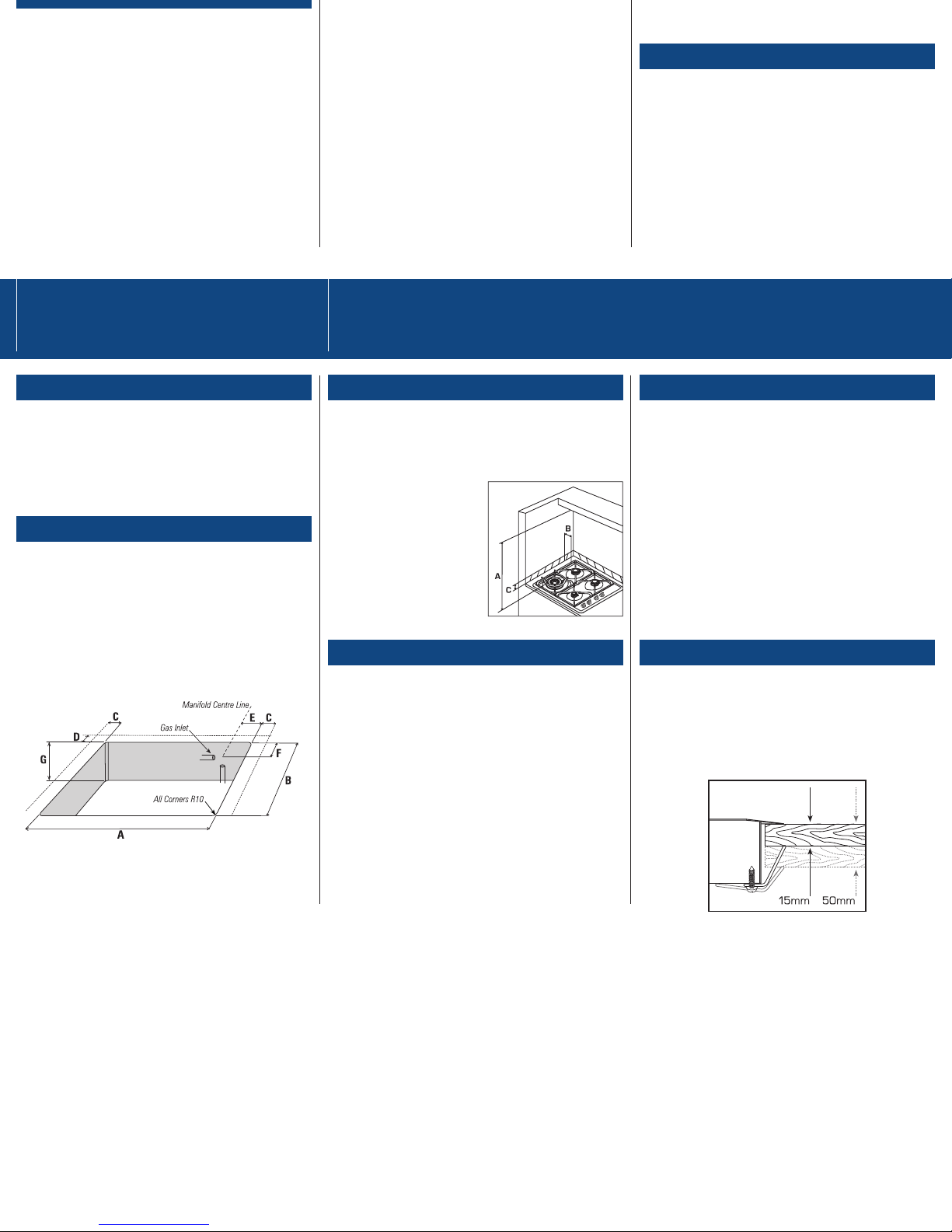
CLAMPING DOWN THE COOKTOP/HOB
Place the cooktop into the cutout and tighten it with the supplied
clamps. DO NOT OVER TIGHTEN.
The clamps will cope with bench thickness 15-50mm
(see diagram) when used in the two orientations.
Dimensions Clearances
When used with a flexible hose, the connector on the wall should be
between 800mm to 850mm above the floor and in the region outside
the width of the appliance to a distance of 250mm. This should be
accessable with the appliance installed.
 Loading...