

Page 1
Gas Cooktops
Models
GC600
GC600W
GC600F
GC600WF
GC600WFC
GC600QJET
GC900
GC900WFC
GC9002WFC
GC900QJET
GC9002QJET
GC36
GC36WAC
599001
Page 2

SERVICE MANUAL 599001 Revision B December 2001 Ref: SB/sh/1997
PRODUCTS
Brand Fisher & Paykel, Shacklock, Unbranded
Model Series Code
GC600 1 84494, 87344, 87362, 87408
GC600F 1 87364, 87388
GC600W 1 84495, 84496, 87333, 87363, 87369, 87410
GC600WF 1 84502, 84504, 87350, 87365, 87381, 87382
GC600WFC 1 84506, 87332, 87366, 89040, 89041
GC900WFC 1 84510, 87334, 87390, 89042
GC9002WFC 2 87674, 87676
GC600Q JET 1 87640, 87666
GC900Q JET 1 87640, 87666
GC9002Q JET 2 87675, 87677, 88263, 88264
GC36WAC 1 88253
For Australia For New Zealand For USA/Canada
Fisher & Paykel Customer Services Fisher & Paykel Customer Care Fisher & Paykel Customer Care
PO Box 798 PO Box 14-917 27 Hubble
19 Enterprise Street Panmure Irvine, CA 92618
Cleveland, Queensland 4163 Auckland Laguna Hills, CA 92653
Australia New Zealand USA
Tel: (07) 3826 9122 Tel: 0800 37 2273 TOLL FREE 1-888-936 7872
Fax: (07) 3826 9164 Fax: (09) 273 0656 Fax (949) 790 8913
Email: parts@fp.com.au Email: Customer.Care@fp.co.nz www.usa.fisherpaykel.com
A.C.N. 003 335 171
For United Kingdom For Republic of Ireland For Singapore
Fisher & Paykel Limited C&F Quadrant Fisher & Paykel (S) Pte Ltd
Broxell Close Quadrant House 150 Ubi Avenue 4
Wedgnock Industrial Estate Chapelizod #02-00, Sunlight Building
Warwick CV34 6QF Dublin 20 Singapore 408825
England Ireland
Tel: +44 1926 626 700 Tel: 01626 5711/4917 Tel (+65) 547 0100
Fax: +44 1926 626 701 Fax: 01 626 7863/3251 Fax (+65) 547 0123
1
Page 3

CONTENTS
1.0 SPECIFICATIONS ................................................................................................................... 3
1.1 Product Dimensions ........................................................................................................... 3
1.2 Model Explanation ............................................................................................................ 3
1.3 Bench Cut-Out Dimensions ............................................................................................... 3
1.4 Burners ............................................................................................................................. 4
1.5 Controls ........................................................................................................................... 5
1.6 Electrical ........................................................................................................................... 5
1.7 Gas Rating (MJ/h / kw) ......................................................................................................5
1.8 General Warning ............................................................................................................... 5
2.0 WIRING DIAGRAM ................................................................................................................. 6
3.0 REPLACEMENT OF BURNER ORIFICE & LOW SETTING ................................................ 7
3.1 Minimum Setting or Turn Down ......................................................................................... 7
3.2 Conversion to Different Gas Type ..................................................................................... 8
4.0 REMOVAL OF HOB TOP ......................................................................................................... 9
4.1 How to Remove Hob Top ................................................................................................. 9
5.0 REMOVAL OF COOKTOP FROM BENCH/COUNTERTOP .................................................10
5.1 To Remove the Product From the Bench/Countertop .........................................................10
6.0 REPLACEMENT & SERVICING OF ELECTRONIC IGNITION ...........................................11
6.1 To Replace an Electrode ....................................................................................................11
6.2 To Replace Ignition Box .................................................................................................... 11
6.3 To Replace the Microswitch Loom (GC600, GC600W and GC36 Only) ...........................11
7.0 REPLACEMENT & SERVICING OF FLAME FAILURE ........................................................12
7.1 To Test Flame Failure ........................................................................................................12
7.2 To Replace a Thermocouple ..............................................................................................12
8.0 GAS VALVES ...........................................................................................................................13
8.1 To Change a Gas Valve .....................................................................................................13
8.2 To Re-Grease Gas Valves .................................................................................................13
9.0 PROBLEM SOLVING (Excluding Auto Reigntion) ....................................................................14
9.1 Gas Doesn't Light - No Spark ...........................................................................................14
9.2 Gas Doesn't Light - Spark But No Ignition .........................................................................14
9.3 Flame Doesn't Stay When Gas Valve is Released ...............................................................14
10.0 PROBLEM SOLVING AUTO REIGNITION ...........................................................................16
10.1 Gas Doesn't Light - No Spark ...........................................................................................16
10.2 Gas Doesn't Light - Spark but no Ignition .......................................................................... 16
10.3 Sparking Continuously After Ignition ..................................................................................16
10.4 Flame Goes Out on Low Setting ........................................................................................17
10.5 Flame is Distorted or Large and Yellow ..............................................................................17
2
Page 4

3
1.0 SPECIFICATIONS
1.1 Product Dimensions
GC600 Series GC900 Series GC9002/GC36
Series
Length 578mm 860mm 914mm (36")
Width 511mm 511mm 533mm (21")
Depth below bench 40mm 40mm 40mm (15/8")
1.2 Model Explanation
GC = Gas Cooktop
600 = 600mm wide
900 = 900 mm wide
9002 = 900mm wide, Series 2
F = Flame Failure
W = Woprk
C = Cast Iron Pan Supports
Q = Quantum sub-brand
JET = Quantum Model Name
GC36WAC = 36" Gas Cooktop for USA With Auto Reignition and Griddle Burner
1.3 Bench Cut-Out Dimensions
GC600 Series GC900 Series GC9002/GC36
Series
Length 560mm 842mm 842mm (333/16")
Width 490mm 490mm 490mm (193/8")
Depth for clearance 45mm 45mm 45mm (13/4")
Clearances (USA Only)
§ Minimum horizontal distances from side and back of appliance to adjacent vertical combustible
walls (extending a minimum of 18" (457mm) from above the top panel) must be 4" (100mm)
from the left side wall, 1" (25mm) from the right side wall and 21/2" (64mm) from the rear wall.
§ Minimum horizontal distance from front edge of counter to front side of appliance 21/2"
(64mm). Where this reduces the distance between the back edge of the appliance and the
adjacent wall to less than 21/2" (64mm), this wall must be of a non combustible material.
§ Minimum clearance to combustible surface centred above cooking surface 30" (762mm).
§ Minimum horizontal distance between overhead cabinets installed on either side of this
appliance 36" (914mm).
§ Maximum depth of overhead cupboards, 13" (330mm).
§ These distances shall be from the outermost edge of the top panel.
Page 5
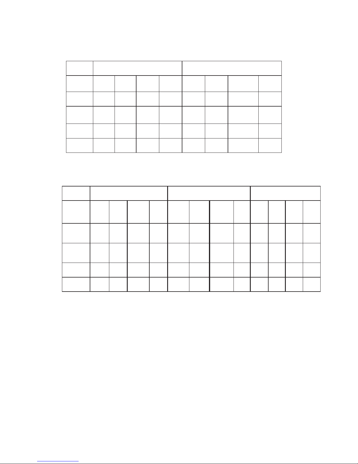
1.4 Burners
GC600 Series
GC900 / GC9002 / GC36
ZN/ailartsuAEI/BG
GN
)APk1(
h/JM
cifirOe
eziS
GPL
)aPk57.2(
h/JM
ecifirO
eziS
I(GNH2)
)rabm02(
Wk
ecifirO
eziS
I(GPL
+3
)
)rabm73/03-82(
Wk
ecifirO
eziS
yrailixuA
thgiRtnorF
7.358.01.455.00.157.08.054.0
dipaRimeS
&tfeLraeR
thgiR
1.61.14.67.02.21.12.257.0
koW
tfeLtnorF
518.15150.14.353.18.258.0
dipaR
tnorFtfeL
3.115.13.1129.0
ZN/ailartsuA
2009CG/009CG
EI/BG
2009CG
adanaC/ASU
63CG
GN
)APk1(
h/JM
ecifirO
eziS
GPL
)aPk57.2(
h/JM
ecifirO
eziS
I(GNH2)
)rabm02(
Wk
ecifirO
eziS
I(GPL
+3
)
73/03-82(
)rabm
Wk
ecifirO
eziS
"4GN
UTB
ecifirO
eziS
"11PL
UTB
ecifirO
eziS
/yrailixuA
remmiS
thgiRtnorF
7.358.07.355.02.157.00.155.0000458.0005355.0
dipaRimeS
&tfeLraeR
thgiR
9.7*3.19.7*8.02.21.12.257.00008*3.10008*8.0
/tnorFtfeL
koW
518.15150.12.455.19.30.1000,318.1000,3150.1
/ertneC
tellikS
0154.10158.08.252.12.257.0005,954.1005958.0
*1.3 / 0.8 orifices replace 1.1 / 0.7 orifices.
These are available from spare parts and replace the previous size.
Note:Kits of high altitude orifices are available for USA/Canada (these are also suitable for
Aus/NZ 900/9002 models). NG Part No. 530463 LPG Part No. 530464
These orifices should be used at approximately 6000ft or above.
4
Page 6
1.5 Controls
GC600/GC600W/GC600F 4 x Standard Gas Valves P/N 530029
GC600WF/GC600WFC/GC600QJET 4 x Flame Failure Valves P/N 530302
GC900WFC/GC9002/GC900QJET/GC9002QJET 5 x Flame Failure Valves P/N 530302
GC36 5 x Standard Gas Valves P/N 530029
1.6 Electrical
600 Series
Mains Powered Ignition System - 220/240V 0.6VA Part No. 530032
900 Series
Mains Powered Ignition System - 220/240V 0.6VA Part No. 530033
GC36 Series
Mains Powered Auto Reignition System 120V 60Hz 2VA Part No. 530308
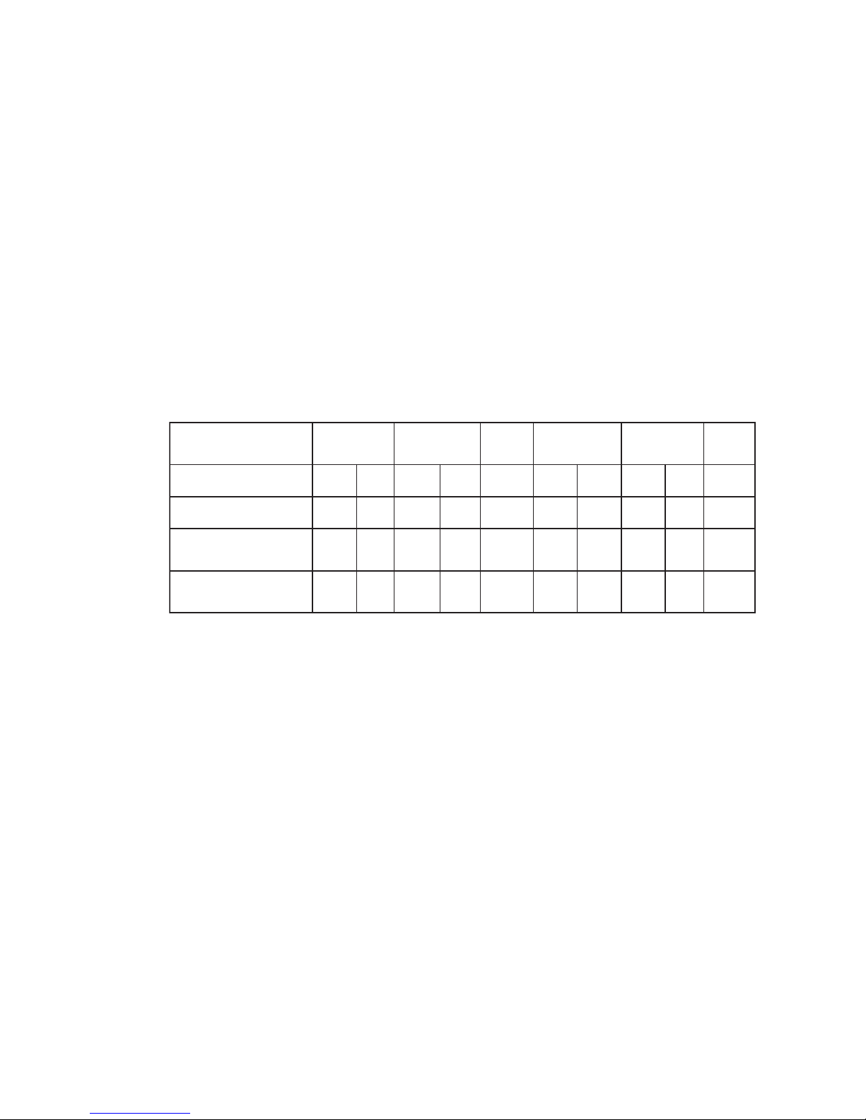
1.7 Total Gas Rating (MJ/h / kw / BTU)
Serial and model numbers are located on the underside of the product. An extra label is provided to
the installer in Aus/NZ to be placed in a convenient place.
1.8 General Warning
Gas products can only be installed and serviced by qualified Gas Service Persons.
,ZN/suA
GN
,EI/BG
GN
,ASU
GN
,ZN/suA
GPL
,EI/BG
GPL
,ASU
PL
h/JMWkh/JMWkUTBh/JMWkh/JMWkUTB
F006CG/006CG2.726.7-2.828.7-
/CFW/FW/W006CG
TEJQ006CG
9.036.87.138.8- 9.139.88.828-
seireS2009/009CG
63CG/9teJ
5.444.214.546.21005,245.444.214.140.11000,24
5
Page 7

6
2.0 WIRING DIAGRAM
Schematic Wiring Diagram for GC600, GC900 & GC9002 Series Gas Cooktops Ignition
Circuit
IGNITION
BOX
220/240V
0.5VA
P
N
E
DANGER - 240V
DISCONNECT
POWER BEFORE
SERVICING UNIT
TO
ELECTRODES
IGNITION
SWITCHES
GC900 SERIES ONLY
(5 BURNERS)
0.6VA
Schematic Wiring Diagram for GC36 Gas Cooktops Ignition Circuit (USA & Canada Only)
Page 8

7
3.0 REPLACEMENT OF BURNER ORIFICE & LOW SETTING
3.1 Minimum Setting or Turn Down
Note: This is not possible in the UK and Ireland as the gascocks have been sealed.
This has been set at the factory but can be checked after the correct pressure has been reached.
To adjust for minimum setting, if needed. You will need a 2.5 diameter x 45mm (7/64" diameter x13/4")
screwdriver. (In the USA, this screwdriver is available as Part No. FB200467.)
3.1.1 Remove the knobs.
3.1.2 Ignite the burner and set the knob to its minimum position.
3.1.3 Rotate the turn down screw (down the hole in the valve spindle). Rotate slowly until a minimum
regular flame is achieved. (The flame will diminish when the screw is turned clockwise and increase
when turned anti-clockwise).
3.1.4 When the setting is right check regulation by quickly rotating the knob from the maximum to the
minimum delivery position. The flame must not go out. Replace the knob.
This picture may not exactly represent all cooktops.
Page 9

8
3.2 Conversion to Different Gas Type
Note: For the UK/Ireland, the products must not be converted between gases. The gas
taps have been sealed.
Burners can be used with NG or LPG types of gas, provided that the injector orifice appropriate for
the gas delivered are installed. Use a 7mm (9/32") box spanner to remove the orifice.
To change the injector orifice:-
3.2.1 Turn off the mains supply.
3.2.2 Ensure all gas cocks are turned off.
3.2.3 Remove all burner heads.
3.2.4 Unscrew the injector orifice using a 7mm socket and replace
them with the correct ones. (Size numbers stamped on side or
the top.) e.g:- 70 = 0.70mm
3.2.5 Reset minimum setting (see 3.1).
The label supplied with the orifices can be placed over the existing gas type label to indicate the
change.
Note:Kits of high altitude orifices are available for USA/Canada (these are also suitable for Aus/NZ
900/9002 models). NG Part No. 530463 LP Part No. 530464
These orifices should be used at approximately 6000 feet and above.
3.2.6 To Change the Gas Pressure (4"NG, 11"LP): (USA/Canada Only)
1. Unscrew the cap from the regulator.
2. Check the orientation of the plastic conversion plug, and if necessary, unscrew, turn over and
screw back in (wide section away from cap for LP and against cap for NG - see diagram
below for appropriate orientation).
3. Replace regulator cap.
4. Test gas pressure (test point provision on side of regulator). When converting the regulator for
different settings, the function of the regulator must be checked at a pressure at least 1"WC
(249Pa) above the specified manifold pressure.
Page 10

9
4.0 REMOVAL OF HOB TOP
4.1 How to Remove Hob Top
4.1.1 Lift off trivets and burner heads.
4.1.2 Pull off knobs.
4.1.3 On 600 Series Flame Failure models unscrew the nut securing each flame failure probe
M7 (9/32") box socket.
4.1.4 Remove the two screws holding each burner. (To prevent damaging the screw head use a
No. 1 Philips screwdriver.)
4.1.5 Lift off hob top hinging from the back. NB: The edge on stainless models can be sharp. (The
electrodes unplug from the ignition box if you want to get the hob out of the way. They go back
in any order). Disconnect the earth wire from hob terminal.
4.1.6 If you need to change the 600 Series hob, the electrodes may be removed by unlatching the
locating springs.
4.1.7 To replace, reverse the procedure.
Page 11

10
5.0 REMOVAL OF COOKTOP FROM BENCH/COUNTERTOP
It is probably easiest to service the internal components (gas valves, electronics) by removing the hob
top rather than removing the product from the bench/countertop (see Section 4).
5.1 To Remove the Product from the Bench/Countertop
5.1.1 Disconnect the electrical supply.
5.1.2 Turn off gas supply and disconnect.
5.1.3 Loosen the clamping brackets at the front/sides (underneath).
5.1.4 Lift product out.
Page 12

11
6.0 REPLACEMENT & SERVICING OF ELECTRONIC IGNITION
6.1 To Replace an Electrode
6.1.1 Disconnect from power.
6.1.2 Remove the product top panel - (see Section 4).
6.1.3 Unlatch the appropriate locating spring and remove the electrode. Replace
6.1.4 Reassemble in reverse order.
6.2 To Replace Ignition Box
6.2.1 Disconnect from power.
6.2.2 Remove the product top panel - (see Section 4).
6.2.3 Unplug the electrodes and the multiway plug from the ignition box.
6.2.4 Replace the box. the igntion box is held down by double sided foam tape.
6.2.5 For the auto reignition box.
Electrode wires must be plugged into correct terminals. Terminal Numbers on the ignition box
correspond to:
#1: Front left burner
#2: Front right burner
#3: Middle burner
#4: Rear left burner
#5: Rear right burner
6.2.6 Reassemble in reverse order.
6.3 To Replace the Microswitch Loom (GC600, GC600W and GC36 Only)
6.3.1 Disconnect from power.
6.3.2 Remove the hob top - (see Section 4).
6.3.3 Remove the circlips from each gas cock to free the microswitch assembly. Lift off microswitch
assembly and replace.
6.3.4 Reassemble in reverse order.
Page 13

12
7.0 REPLACEMENT & SERVICING OF FLAME FAILURE
(Refer also Section 9 - Problem Solving)
7.1 To Test Flame Failure
7.1.1 Ensure thermocouple is held in the flame even if the hob is removed.
7.1.2 Ignite the burner, hold the knob down for five seconds. Release. Burner should stay alight.
7.1.3 Turn down to low and blow out. After about 10-15s, the flame failure should stop the flow of gas.
(You should hear a click).
7.1.4 If 7.1.2 or 7.1.3 are not met (see Section 9 - Problem Solving).
7.2 To Replace a Thermocouple
7.2.1 Remove the hob (see Section 4).
7.2.2 Unscrew (small hex, 8 AF) from end of gas valve and replace.
7.2.3 Test thermocouple works before replacing hob.
Page 14

13
8.0 GAS VALVES
8.1 To Change a Gas Valve
8.1.1 Turn off gas supply and electricity.
8.1.2 Remove the hob top (see Section 4).
8.1.3 Disconnect ignition switch wires. For non Flame Failure models, remove the circlip from each
gascock to free the microswitch assembly. Lift off microswitches.
8.1.4 Disconnect male 1/2" nut on rear of unit to gas supply.
8.1.5 Undo nuts holding aluminium tubes to gas valve.
8.1.6 Remove a screw holding manifold to basepan.
8.1.7 Lift out manifold, remove screws holding valve to manifold bracket.
8.1.8 Change gas cocks.
8.1.9 Replace in reverse order. Leak test with soapy water. Reconnect ignition switch wires (replace
microswitch for non Flame Failure models).
Note: Remember to test the gas valve outlet with the valve turned on.
8.1.10 Check turn down setting (see Section 5).
8.1.11 Replace hob.
8.2 To Re-Grease Gas Valves
8.2.1 Remove product top panel.
8.2.2 Remove circlips from each gas valve to free the microswitch assembly. Lift off microswitches.
8.2.3 Unscrew the two Philips screws on the top of the gas valve.
8.2.4 Gently lift out the valve cone, clean with solvent.
8.2.5 Re-grease with high temperature grease. (e.g. ROCOL HT, Otimol HT2EP, Ragasine Moly
LM). Replace.
8.2.6 Move it around, remove excess grease, remove and check holes in the core or body are not blocked,
replace.
8.2.7 Open and close a couple of times.
8.2.8 Check for leaks with leak detection fluid e.g. Rocol Leak Detection spray) and re-assemble in reverse
order.
Page 15

14
9.0 PROBLEM SOLVING (excluding Auto Reignition)
9.1 Gas Doesn't Light - No Spark (See also Section 6)
Check source of mains supply.
9.1.1 Check electrodes/burners are clean (use rubbing Alcohol and an old tooth brush).
9.1.2 Check that spark gap is not too wide (burners sitting right).
9.1.3 If only one or two burners are getting a spark, swap over high tension ignition leads at the ignition box.
If burners which were igniting before are no longer getting a spark, fault is in the box. If burners which
were igniting before are still igniting after changing leads, fault is in the ignition lead/electrode.
9.1.4 Check continuity from the box to the electrode and from the burner or earthing point to the earth
connection on the box.
9.1.5 Check that high tension leads are not coiled, or lying on the basepan, as this may result in a loss of
voltage to the electrode. (Use correct length leads and locate in correct position.)
9.2 Gas Doesn't Light - Spark but no Ignition
9.2.1 Check gas supply (including output pressure of regulator).
9.2.2 Check if any burners light (with match).
9.2.3 Check spark gap (set to approximately 3mm).
9.2.4 Check spark earthing to correct position on burner.
9.2.5 Check that high tension leads have not been coiled, as this may result in a loss of voltage and a spark
of insufficient energy to ignite the gas. (Use correct length high tension leads and locate correctly.)
9.3 Flame Doesn't Stay When Gas Valve is Released (See also Section 7)
9.3.1 Remove knob and retry without the knob.
There have also been instances of the clamping brackets being overtightened and distorting the panel
enough to allow the knob to bottom out.
9.3.2 Check the flame envelopes the tip of the thermocouple.
Check the thermocouple tip is free from carbon or other deposits.
Check the thermocouple for any physical damage e.g. kinks, corrosion at the tip.
Check the thermocouple nut is tight on the gas valve to ensure electrical contact.
Page 16

15
9.3.3 Test Thermocouple
Turn off gas and electrical supply.
Remove the hob top but replace the burner head on the afflicted burner.
Disconnect the thermocouple from the gas valve.
Set your multimeter onto DC millivolts.
Attach with alligator clips to outer copper sheath (+) and the aluminium lump on the end (-).
Turn on gas, light burner (you will have to keep holding the knob down).
Hold the thermocouple tip in the flame and observe the meter. If no reading, - replace the
thermocouple. If it reads approximately greater than 20mV it's working OK - replace the gas valve.
(Could check by swapping a coil/magnet from one of the other valves.)
Page 17

10.0 PROBLEM SOLVING AUTO REIGNITION
10.1 Gas Doesn't Light - No Spark
Check source of mains supply.
Check spark gap is not too wide (burners sitting correctly).
Check electrodes/burners are clean (use rubbing alcohol and an old toothbrush).
Check continuity from the box to the electrode and from the burner or earthing point to the earth
connection on the box.
Check the high tension leads are not coiled, as this may result in a loss of voltage to the electrode.
(Use correct length leads and locate in correct position.) Check for damage to wire insulation and
that the leads are not against parts that will heat up during operation.
10.2 Gas Doesn't Light - Spark but no Ignition
Check the cooktop and regulator are set up for the correct gas type and pressure (factory set for
NG).
Check location of ignitors and make sure spart gap is not too wide.
Check the burner components including the burner cap are sitting correctly.
Check electrodes/burners are clean (use rubbing alcohol and an old toothbrush).
Check the high tensions leads have not been coiled, as this may result in a loss of voltage and a spark
of insufficient energy to ignite the gas. (Use correct length leads and locate in correct position.)
10.3 Sparking Continuously after Ignition
Check electrodes are clean (use rubbing alcohol and an old toothbrush).
Check the cooktop is correctly earthed (lack of earthing will cause a problem).
Check the polarity of the electrical supply is correct to the ignition box.
Check the cooktop and regulator are set up for the correct gas type and pressure (factory set for
NG).
10.3.1 Determine the Problem Burners
1. Turn all burners off.
2. Turn on one burner at a time to check which are OK and which continue sparking after ignition.
With each you should check the high position, the low position and the behaviour with a large
pot, before turing it off and moving on to the next burner.
3. If the problems occurs with the rear (semi rapid) burners, check that they have the 'hooked'
electrode. Part No. 536 486.
16
Page 18

4. If the problem occurs with the front right, simmer burner
Check that there is enough gas coming through the 'electrode' port at the rear of the burner skirt,
to maintain a stable flame. Try adjusting the low setting.
5. If the problem occurs with the front left 'triple ring' burner. Install a new electrode,
(Part No. 531603). Check that the ceramic body has not been damaged.
6. Check each burner lights and doesn't continue sparking.
10.4 Flame Goes Out on Low Setting
Check the cooktop and regulator are set up for the correct gas type and pressure (factory set for
NG).
Check the burners low setting is correct (see Section 3.1).
10.5 Flame is Distorted or Large and Yellow
Check the cooktop and Regulator are set up for the correct gas type and pressure (factory set for
NG).
Check the burner components including the burner cap are sitting correctly.
17
 Loading...