

Page 1
CANADA / USA
INSTALLATION INFORMATION
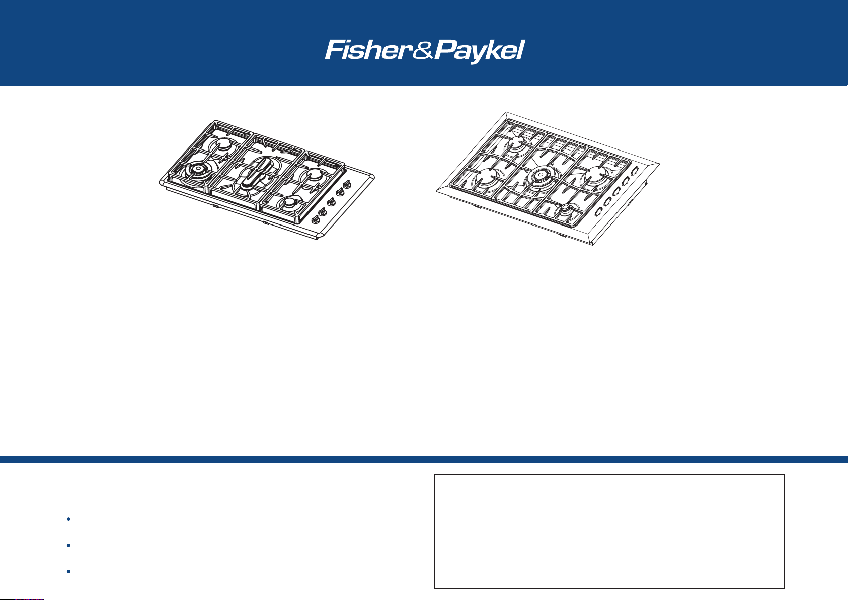
GC36 and GC901 SERIES
GAS COOKTOP
Part Number
599048K
Date of Issue
DECEMBER 2002
PAGE 1 OF 6
GC36 GC901/M
IMPORTANT!
Please make this information available to the person responsible for installing this cooktop as it could reduce your installation costs.
To the installer: Please leave these instructions with the appliance. Inform the customer to
retain for future reference.
Please follow installation information carefully. If in doubt consult your local building
regulations, local gas authority codes and electrical regulations.
The appliance is to be installed only by an authorized person (in Massachusetts this must be
a Massachusetts licensed gas fitter).
This product is supplied with an additional label containing the model and serial numbers. It
may be affixed to the underside of the product, the inside of a cupboard or to the User Guide.
CAUTION
IN ORDER TO AVOID A HAZARD THESE APPLIANCES MUST BE INSTALLED ACCORDING TO
THESE INSTRUCTIONS.
This product should not be sealed into the bench with silicone or glue. This will make any
future servicing difficult. Fisher & Paykel will not be liable for costs associated with releasing
such products, nor for damage incurred as a result.
Page 2
PAGE 2 OF 6
DO Ensure the countertop is square and level and ensure no structural members interfere
with space requirements.
DO Ensure that there is a power supply receptacle within reach of the cooktop power cord
(30" from the middle of the product). The main cable should not touch any
hot metal parts.
DO Make sure the cooktop is connected to a power supply socket that is electrically
grounded in accordance with local codes or in the absence of local codes, with the
National Electric Code ANSI/FPA 70 or CSA 22.2 (Canada).
DO Make sure the countertop is made of a heat resistant material.
BEFORE YOU START
WARNINGS
This appliance shall be installed in accordance with the installation requirements of the
local gas authority or the appropriate installation code or in the absence of local codes with
the latest National Fuel Gas Code ANSI Z223.1 or CAN B149.1,2(Canada).
Disconnect power before servicing unit.
Be aware of sharp edges when handling stainless steel products. (Carry the product using
the polystyrene ends).
When this appliance is installed it shall not be used as a space heater.
No combustible material or products should be placed on this appliance at any time.
Do not spray aerosols in the vicinity of this appliance while it is in operation.
Not to be installed in a bathroom or bedroom/sleeping quarters.
Flexible appliance connectors shall meet the requirements of ANSI Z21.24 and State Boards.
They shall not exceed 36 inches in length.
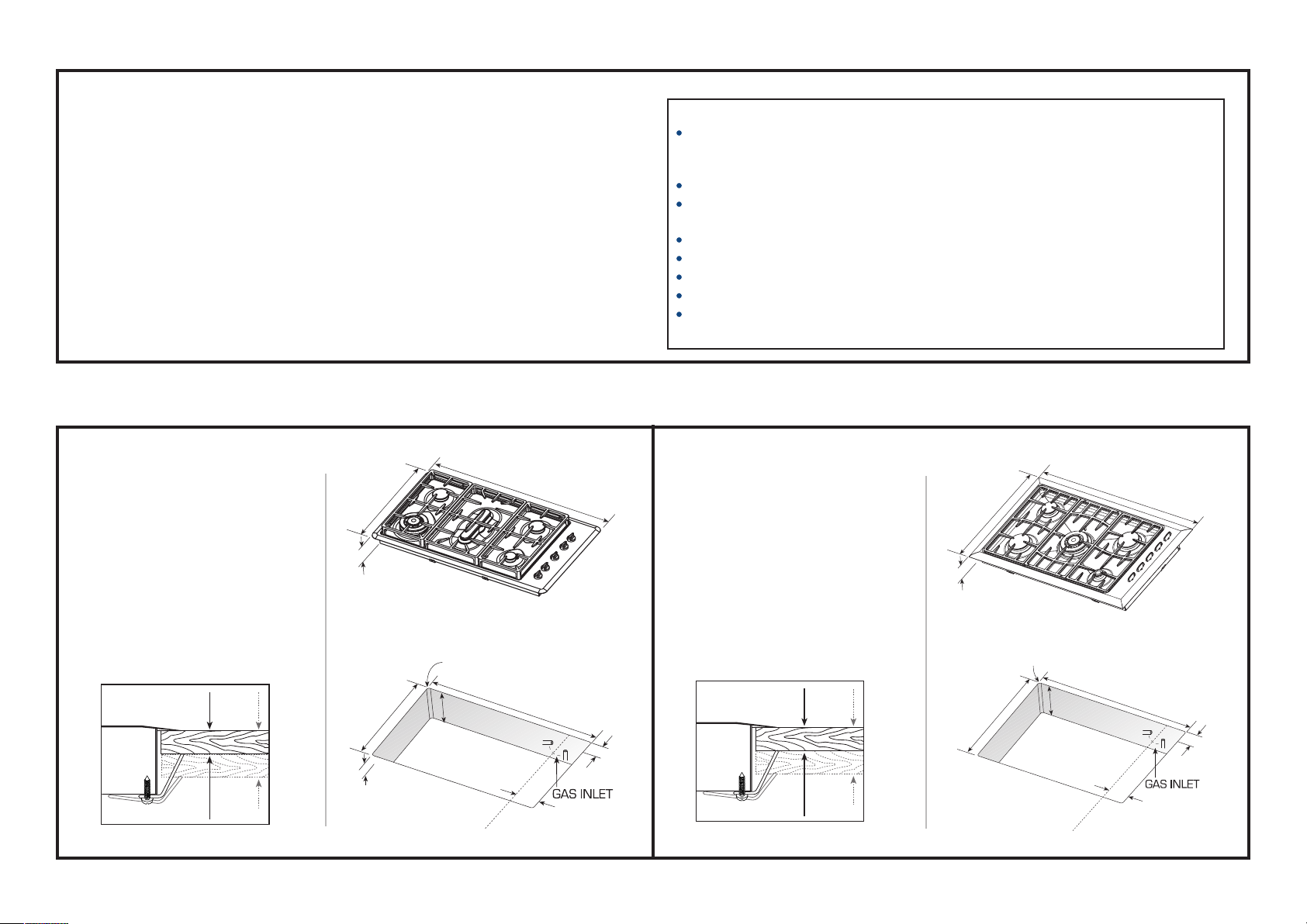
PRODUCT & CUTOUT DIMENSIONS
Clamping Down the Cooktop
Place the cooktop into the cutout and
tighten it with the supplied clamps.
These will cope with the countertop
thicknesses
5
/
8
"- 2" (see diagram
below) when used in the two
orientations shown.
GC36
GC901/M
5
/
8
" - 2"
Do not over tighten
Clamping Down the Cooktop
Place the cooktop into the cutout and
tighten it with the supplied clamps.
These will cope with the countertop
thicknesses
3
/
4
"- 2" (see diagram
below) when used in the two
orientations shown.
3
/
4
" - 2"
Do not over tighten
36" (914mm)
21"
(533.5mm)
5
1
/
8
/
3
" - 18
4
/
3
19
(501 - 478mm)
5
/
" - 2" (15-50mm)
8
bench thickness
" (41.5mm)
"
8
1
1
/
/
R
" -
4
3
/
" (60 mm)
8
2
(5–12.5mm)
minimum
2
Center Line
"
34
3
/
" - 33
(882 - 846mm)
4
Manifold
1"
1
/
" -
"
2
35
(895 - 860 mm)
minimum
5
3
/
" (84 mm)
16
Center Line
36" (914mm)
1
/
" - 33
4
7
Manifold
/
"
8
3
/
"
4
1"
"
2
/
1
21
(546mm)
GC901:
GC901M:
9
2
/
" (65mm)
16
3" (76mm)
3
/
R
16
3
/
"
8
3
/
1
"
16
/
5
20
(524 - 486mm)
(5–12.5mm)
”
8
/
1
” - 19
8
3
/
" - 2" (19 - 50 mm)
4
bench thickness
Page 3

PAGE 3 OF 6
PREPARING THE CUTOUT
D
B
A
C
F
E
GC36
Minimum horizontal distances from side and back of
appliance to adjacent vertical combustible walls
(extending a minimum of 18" (C) from above the top panel)
must be 4" from the left side wall, 1" from the right side
wall and 1
1
/
2
" from rear wall.
Minimum horizontal distance from front edge of counter
to front side of appliance 2
1
/
2
" (E). Where this reduces
the distance between the back edge of the appliance and
the adjacent wall to less than 1
1
/
2
" (F), this wall must be
of non combustible material.
Minimum clearance from combustible surface centered
above cooking surface 30" (A).
Minimum horizontal distance between overhead cabinets
installed on either side of this appliance 36" (D).
Maximum depth of overhead cupboards, 13" (B).
These distances shall be from the outermost edge of the
top panel.
Do use easy-to-clean finishes for the wall surfaces
surrounding the cooktop to aid removal of any cooking
stains resulting from use of the cooktop.
GC901 / GC901M
Minimum horizontal distances from side and back of
appliance to adjacent vertical combustible walls (extending
a minimum of 18" (C) from above the top panel) must be
1
1
/
4
" from the left side wall, 1" from the right side wall and
1
1
/
4
" from rear wall.
Minimum horizontal distance from front edge of counter
to front side of appliance 1
1
/
4
" (E). Where this reduces the
distance between the back edge of the appliance and the
adjacent wall to less than 1
1
/
4
" (F), this wall must be of
non combustible material.
Minimum clearance from combustible surface centered
above cooking surface 30" (A).
Minimum horizontal distance between overhead cabinets
installed on either side of this appliance 36" (D).
Maximum depth of overhead cupboards, 13" (B).
These distances shall be from the outermost edge of the
top panel.
Do use easy-to-clean finishes for the wall surfaces
surrounding the cooktop to aid removal of any cooking
stains resulting from use of the cooktop.
Page 4

PAGE 4 OF 6
GAS SUPPLY CONNECTION
A manual valve must be installed in an accessible location in the gas line external to the
appliance for the purpose of turning on or shutting off gas to the appliance.
(In Massachusetts
such shutoff devices should be approved by the Board of State Examiners of Plumbers & Gas Fitters).
This appliance can be used with either LP gas or Natural gas. It is shipped from the
factory adjusted for use with Natural gas.
For use with a gas pressure regulator. The regulator supplied can be set for either LP gas or
Natural gas and must be used with this appliance. It has a
1
/
2
" NPT thread.
Gas connection to the product must use the elbow supplied (it has a
1
/
2
" NPT external thread).
Ensure the blue washer (supplied) is located between the elbow and the product
inlet. Failure to use this will cause the product to leak.
CHECKING THE GAS TYPE
GC36
Burners NG Orifice NG LP Orifice LP
(mm) BTU (MJ/h)@ (mm) BTU (MJ/h)@
0.15psi (4”H20) 0.41psi (11”H20)
RH Rear 1.3mm 8,000 (8.4 MJ/h) 0.8mm 8,000 (8.4 MJ/h)
LH Rear 1.3mm 8,000 (8.4 MJ/h) 0.8mm 8,000 (8.4 MJ/h)
RH Front Simmer 0.85mm 3,500 (3.47 MJ/h) 0.55mm 4,000 (4.2 MJ/h)
LH Front Wok 1.75mm 13,000 (13.7 MJ/h) 1.05mm 13,000 (13.7 MJ/h)
Center 1.45mm 9,500 (10 MJ/h) 0.85mm 9,500 (10.0 MJ/h)
GC901 / GC901M
Burners NG Orifice NG LP Orifice LP
(mm) BTU (MJ/h)@ (mm) BTU (MJ/h)@
0.15psi (4”H20) 0.41psi (11”H20)
RH Rear 1.3mm 8,000 (8.4 MJ/h) 0.8mm 8,200 (8.7 MJ/h)
LH Rear 1.1mm 5,800 (6.1 MJ/h) 0.7mm 5,700 (6.0 MJ/h)
RH Front Simmer 0.85mm 3,000 (3.2 MJ/h) 0.55mm 3,500 (3.7 MJ/h)
LH Front 1.3mm 8,000 (8.4 MJ/h) 0.8mm 8,200 (8.7 MJ/h)
Center (GC901) 1.75mm 14,000 (14.8 MJ/h) 1.05mm 13,000 (13.7 MJ/h)
Center (GC901M) 2.15mm 20,000 (21.1 MJ/h) 1.22mm 19,000 (20 MJ/h)
LP
NG
Instructions for converting the regulator between NG and LP
1. Unscrew the cap from the regulator.
2. Check the orientation of the plastic conversion plug, and if necessary, unscrew, turn over
and screw back in (wide section away from cap for LP and against cap for NG - see
diagram below for appropriate orientation.
3. Replace regulator cap.
4. Test gas pressure (test point provision on side of regulator). When converting the regulator
for different settings, the function of the regulator must be checked at a pressure at least
1" WC (0.036 p.s.i.) above the specified manifold pressure.
Blue Washer
(Note: this diagram is of GC36 but is
similar for GC901 and GC901M).
Page 5

The label supplied with the orifices can be placed over the existing gas label to indicate the change.
High altitude orifices are available from Fisher & Paykel USA (see address).
GC36 NG Kit Part No. 530463
LP Kit Part No. 530464
GC901/M NG Kit Part No. 531566
LP Kit Part No. 531567
PAGE 5 OF 6
TESTING AND SETTING
After installing the gas supply and making all connections check thoroughly for possible leaks. Turn all control knobs on unit to "off" position. Open the valve on the gas supply. Using a leak
detection fluid (e.g. Rocol leak detection spray) check each gas connection one at a time by brushing the solution over the connection. The presence of bubbles will indicate a leak. Tighten the
fitting and recheck for leaks.
Leak testing of the appliance shall be conducted according to the manufacturer's instructions.
Turn on burner valve and light each burner. Check for a clear blue flame without yellow tipping. If burners show any abnormalities, check that they are located properly and in line with the
injector orifice.
The appliance and it's individual shutoff valve must be disconnected from the gas supply piping system during any pressure testing of that system in excess of
1
/
2
p.s.i. (3.5kPa).
The appliance must be isolated from the gas supply piping system by closing it's individual manual shutoff valve during any pressure testing of the gas supply piping system at test pressures at
or less than
1
/
2
p.s.i.(3.5kPa).
Maximum inlet gas supply pressure 4" W.P. Natural Gas, 11" W.P. LP gas.
Minimum gas supply pressure for regulator testing 5" W.P. Natural Gas, 12" W.P. LP gas.
CONVERSION TO DIFFERENT GAS TYPE
Burners can be used with all types of gas, provided that the orifices appropriate for the gas
delivered are installed.
You will need a
9
/
32
" (7mm) socket (and a
13
/
32
" (10mm) socket for the GC901M).
To change the orifices:
1. Turn off the mains supply.
2. Ensure all gas valves are turned off.
3. Remove all grates and burner heads.
4. Pull off knobs.
5. Remove the two screws securing each burner (three on the wok burner).
6. Partially lift the hob and unplug the electrode on the simmer burner
(CAUTION: the edge can be sharp).
7. Unscrew the orifices and replace them with the correct ones.
(Size numbers are stamped on the side e.g. 70 = 0.70mm).
8. Set the brass venturi on the wok burner to a distance of
3
/
5
”
(15mm) as indicated.
9. To replace the hob, repeat steps 4-6 in reverse.
Changing the orifice
(
Note: this diagram is of GC901 but is similar for GC36).
GC901M only GC901M only
Page 6

PAGE 6 OF 6
MINIMUM SETTING OR TURNDOWN
This has been set at the factory for NG but can be checked after the correct pressure has been
reached. To adjust for minimum setting, if needed. You will need a Ø
7
/
64
" x 1
3
/
4
" (Ø2.5 x 45mm)
screwdriver. (A suitable screwdriver is available as Fisher & Paykel spare part. FB200467).
1. Ignite the burner and set the knob to its minimum position.
2. Remove the knobs.
3. Rotate the turn down screw (down the hole in the spindle) while holding the shaft.
Rotate slowly until a minimum regular flame is achieved. (The flame will diminish when
the screw is turned clockwise and increase when turned counter clockwise).
4. When the setting is right check regulation by quickly rotating the knob from the
maximum to the minimum delivery position. The flame must not go out and the
autoreignition should not click. Replace the knob.
Minimum setting adjustment
(Note: this diagram is of GC901 but is similar for GC36).
A Service Summary is attached to the underside of the product.
For replacement parts or if further help is needed concerning this appliance call:
TOLL FREE 1 888 9 FNP USA (1 888 936 7872)
or write to:
Fisher & Paykel Appliances Inc.
27 Hubble, Irvine
CA 92618
or contact us through our web site,
www.usa.fisherpaykel.com
See the Product Installation Checklist attached to the product.
 Loading...