

Fisher & Paykel FREESTANDING COOKER OR120 User Manual

Installation instructions
and User guide
GB IE
Freestanding cooker
OR120 double oven models


1
Safety and warnings
2
Installation instructions
6
Maintenance instructions
13
Introducing your cooker
16
Using your cooktop
17
Cooktop troubleshooting
21
Using your ovens for the first time
22
Clock and timer
23
Using your oven
24
Cooking functions
25
Automatic cooking
27
Using the warmer drawer
28
Care and cleaning
29
Warranty and service
42
Important!
SAVE THESE INSTRUCTIONS
The models shown in this User Guide may not be available in all markets and are
subject to change at any time. For current details about model and specification
availability in your country, please visit our local website listed on the back cover
or contact your local Fisher & Paykel dealer.
Contents
2
Safety and warnings
WARNING!
Electrical Shock Hazard
Always disconnect the cooker from the mains electricity supply before
carrying out any maintenance operations or repairs.
Failure to do so may result in death or electrical shock.
Important safety precautions
General
To avoid hazard, follow these instructions carefully before installing or using this product.
Please make this information available to the person installing the product as it could reduce
your installation costs.
Installation must comply with your local building and electricity regulations.
Failure to install the cooker correctly could invalidate any warranty or liability claims.
Some appliances have a protective film. Remove this film before using the cooker.
Electrical
This cooker is to be installed and connected to the electricity supply only by an authorised person.
If the installation requires alterations to the domestic electrical system, call a qualified
electrician. The electrician should also check that the electrical system is suitable for the
electricity drawn by the cooker.
The appliance must be connected to the mains, checking that the voltage corresponds to the
value given in the rating plate and that the electrical cable sections can withstand the load
specified on the plate.
A suitable disconnection switch must be incorporated in the permanent wiring, mounted and
positioned to comply with the local wiring rules and regulations. The switch must be of an
approved type installed in the fixed wiring and provide a 3 mm air gap contact separation in all
poles in accordance with the local wiring rules.
The switch must always be accessible.
The power supply cable must not touch any hot parts and must be positioned so that it does not
exceed 75
O
C at any point.
Installation
WARNING!
Cut Hazard
Take care - panel edges are sharp.
Failure to use caution could result in injury or cuts.

3
Safety and warnings
To connect the cooker to the mains, do not use adapters, reducers or branching devices as they
can cause overheating and burning.
This cooker must be connected to a suitable double pole control unit adjacent to the cooker. No
diversity can be applied to this control unit.
The cooker must be earthed.
Gas
This cooker is supplied for use with natural gas only, and cannot be used on any other gas
without modification. See the ‘Maintenance instructions’ for modification to other gas types.
This cooker can only be installed in a room with adequate ventilation. See the ‘Provision for
ventilation’ instructions in the installation instructions following .
4
Operation
Your freestanding cooker has been carefully designed to operate safely during normal cooking
procedures. Please keep the following guidelines in mind when you are using it:
WARNING!
Hot Surface Hazard
Accessible parts may become hot when this cooker is in use.
To avoid burns and scalds keep children away.
Do not touch hot surfaces inside the ovens or warmer drawer.
Use oven mitts or other protection when handling hot surfaces such as oven
shelves or dishes.
Take care when opening the oven doors.
Let hot air or steam escape before removing or replacing food.
Do not touch the cooktop components, burners, trivets/pan supports or the
base when hot.
Before cleaning, turn the cooker off and make sure it is cool.
Failure to do so could result in burns and scalds.
WARNING!
Electrical Shock Hazard
Switch the cooker off at the wall before replacing fuses or the oven lamp.
Failure to do so may result in death or electrical shock.
Safety and warnings
WARNING!
Explosion Hazard
Do not store flammable materials such as gasoline near the cooktop.
Do not store flammable material in the ovens or in the drawers.
Do not spray aerosols near the cooktop during use.
Failure to do so may result in death or serious injury.

5
Important safety precautions
Isolating switch: make sure this cooker is connected to a circuit which incorporates an isolating
switch providing full disconnection from the power supply.
Household appliances are not intended to be played with by children.
Children, or persons with a disability which limits their ability to use the appliance, should have a
responsible person to instruct them in its use. The instructor should be satisfied that they can use
the appliance without danger to themselves or their surroundings.
Safe food handling: leave food in the oven for as short a time as possible before and after
cooking. This is to avoid contamination by organisms which may cause food poisoning. Take
particular care during warmer weather.
Do not place aluminium foil, dishes, trays, water or ice on the oven or warmer drawer floor during
cooking as this will irreversibly damage the surface.
Do not line the walls with aluminium foil.
Do not stand on the doors, or place heavy objects on them.
Do not use harsh abrasive cleaners or sharp metal scrapers to clean the oven door glass since
they scratch the surface, which may result in shattering of the glass.
Do not use a steam cleaner to clean any part of the cooker.
Do not use an asbestos mat or decorative covers between the flame and the saucepan as this may
cause serious damage to your cooktop.
Do not place aluminium foil or plastic dishes on the cooktop burners.
Do not let large saucepans or frying pans overlap the bench as this can deflect heat onto your
benchtop and damage the surface.
Do not let large saucepans, frying pans or woks push any other pans aside. This could make them
unstable or deflect heat onto your benchtop and damage the surface.
Saucepan handles may be hot to touch. Ensure saucepan handles do not
overhang other gas burners that are on. Keep handles out of reach of children.
If the electrical supply cord is damaged, it must only be replaced by an authorised person.
This cooker is not to be used as a space heater.
The use of a gas cooking appliance results in the production of heat and moisture in the room in
which it is installed. Ensure the kitchen is well ventilated. Keep natural ventilation holes open or
install a mechanical ventilation device (mechanical extractor hood).
Prolonged intensive use of the appliance may call for additional ventilation, for example opening
of a window, or more effective ventilation, for example increasing the level of mechanical
ventilation where present.
Safety and warnings
6
Installation instructions
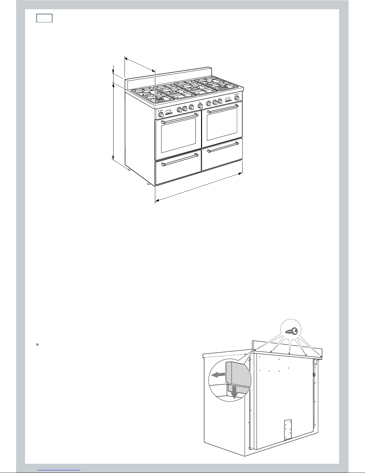
600 mm
1200 mm
MAX 927 mm
MIN 915 mm
120 mm
Fig. 1
Location
The installation conditions, concerning protection against overheating of the surfaces adjacent
to the cooker, must conform to Fig.3a or 3b.
The appliance must be kept no less than 200 mm away from any side wall which exceeds the
height of the hob surface (Fig. 3a or 3b).
The appliance must be housed in heat resistant units.
The walls of the units must be capable of resisting temperatures of 75 °C above room temperature.
Do not install the appliance near flammable materials (eg. curtains).
If the cooker is located on a pedestal, provide safety measures to prevent it falling out.
Assembling the backguard
It is mandatory to install the backguard
Assemble the backguard as shown in Fig. 2
and fix it by screwing the five screws “A”.
A
Fig. 2

7
Installation instructions
450 mm
minimum
minimum
650 mm
0 mm
0 mm
500 mm minimum
200 mm minimum
450 mm
minimum
minimum
650 mm
20 mm
20 mm
500 mm minimum
200 mm minimum
Gas connection made
using rigid or flexible
metal pipe.
Class 2
Subclass 1
Class 1
Gas connection made
using rubber hose
which must be visible
and easily inspected or
using rigid or flexible
metal pipe.
Fig. 3a
Fig. 3b
8
Installation instructions
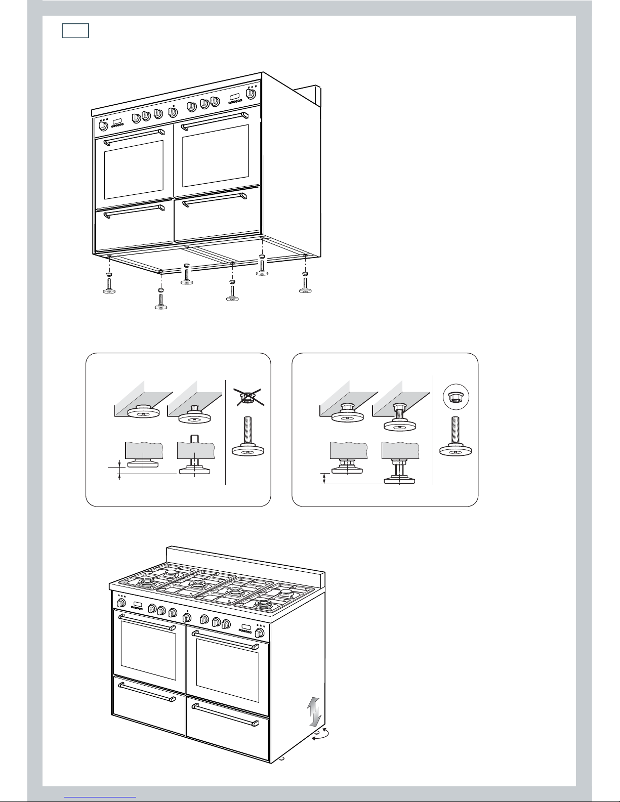
+ 8 mm
+ 8 mm
0 mm
+ 12 mm
Levelling the cooker
Important!
Using the supplied adjustable feet is
MANDATORY. For safety reasons and to
ensure adequate ventilation, the cooker
chassis MUST NOT sit directly on the floor, a
plinth, or other support surface.
The cooker is already fitted with six
levelling feet. Level the cooker by
screwing or unscrewing the feet
(Fig. 4d). Make sure you follow the
instructions in Figs. 4a, 4b, and 4c.
Note: bolts are supplied with the cooker
in a separate kit.
Fig. 4a
Fig. 4b Fig. 4c
Fig. 4d
9
Installation instructions
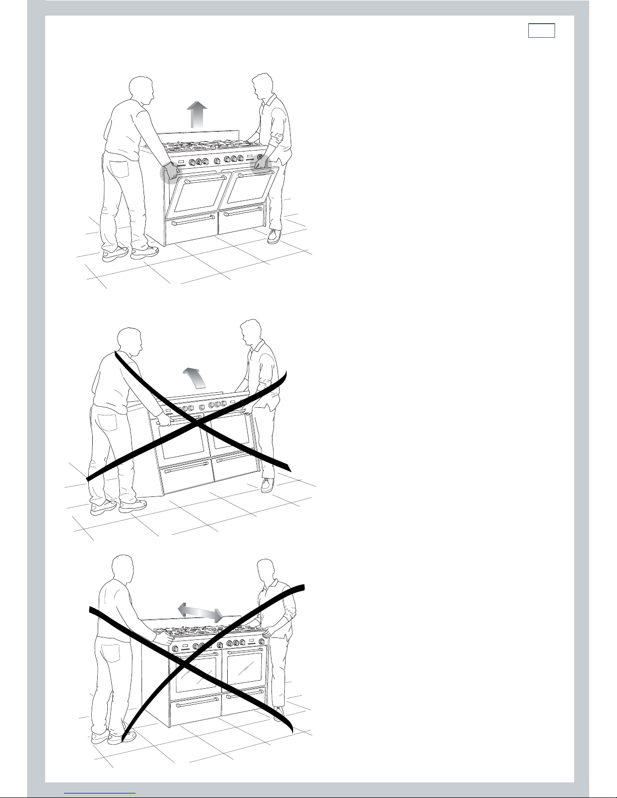
Moving the cooker
Important!
Two people must always raise the cooker, as
shown, to prevent damaging the adjustable
feet.
Do not lift the cooker by the door handles.
DO NOT DRAG the cooker. Lift the feet clear
of the floor.
Ventilation requirements (GB & IE
only)
The appliance should be installed in
a room or space with an air supply in
accordance with BS 5440-2:2000.
For rooms with a volume of less than 5
m
3
: permanent ventilation of 100 mm3
free area will be required.
For rooms with a volume of between 5
m
3
and 10 m3 : permanent ventilation
of 50 cm
3
free area will be required
unless the room has a door which opens
directly to the outside air, in which case
no permanent ventilation is required.
For rooms with a volume greater than
10 m
3
: no permanent ventilation is
required.
Note: regardless of room size, all rooms
containing the appliance must have
direct access to the outside air via an
openable window or equivalent.
Where there are other fuel burning
appliances in the same room, BS
5440-2:2000 should be consulted to
determine the correct amount of free
area ventilation requirements.
Fig. 5a Correctly raising the cooker
Fig. 5c Incorrectly raising the cooker
Fig. 5b Incorrectly moving the cooker
10
Installation instructions
Gas installation (GB & IE only)
Important!
This cooker uses NATURAL GAS only and cannot be used on any other gas without modification. This
appliance is manufactured for conversion to LPG if required. If the injectors are not supplied they can be
obtained from the After-Sales Service.
Installation and service regulations
Important!
This appliance must be installed and serviced only by a suitably qualified and registered person, and in
accordance with the current editions of the following standards and regulations or other locally applicable
regulations:
Gas Safety (Installation and Use) Regulations
Building Regulations
British Standards
Regulations for Electrical Installation
Failure to install the appliance correctly could invalidate any manufacturer’s warranty
and lead to prosecution under the above-quoted regulation.
Gas connection
The installation of the cooker to Natural Gas or LP Gas must be carried out by a qualified
gas engineer. Installers shall take due account of the provisions of the relevant British
Standards Code of Practice, the Gas Safety Regulations and the Building Standards (Scotland)
(Consolidation) Regulations issued by the Scottish Development Department.
Note: It is recommended that the gas connection to the cooker is installed with a flexible
connecting tube made to BS 5386.
Installation to Natural gas
Installation to Natural Gas must conform to the Code of Practice, etc. The supply pressure for
Natural Gas is 20 mbar.
Installation to Liquid Petroleum gas
This appliance must only be connected to LPG after an LPG conversion kit has been fitted. The
installation must conform to the relevant British Standards.
Important!
Only a suitably qualified and registered person may convert the appliance to a different gas type.
When using Butane gas a supply pressure of 28 -30 mbar is required.
When using Propane gas a supply pressure of 37 mbar is required.
11
Notes:
Flexible hoses can be used where the sited ambient temperature of the hose does not exceed
70°C. These hoses must be manufactured in accordance with BS669 part 1 and be of the correct
construction for the type of gas being used.
Gas hoses designed for natural gas MUST NOT be used for supplying LPG gas (LPG gas hoses can
be identified by a either a red band or stripe on the rubber outer coating of the hose).
The hose should not be crushed or trapped or be in contact with sharp or abrasive edges. It
should also not be subjected to corrosion by acidic cleansing agents.
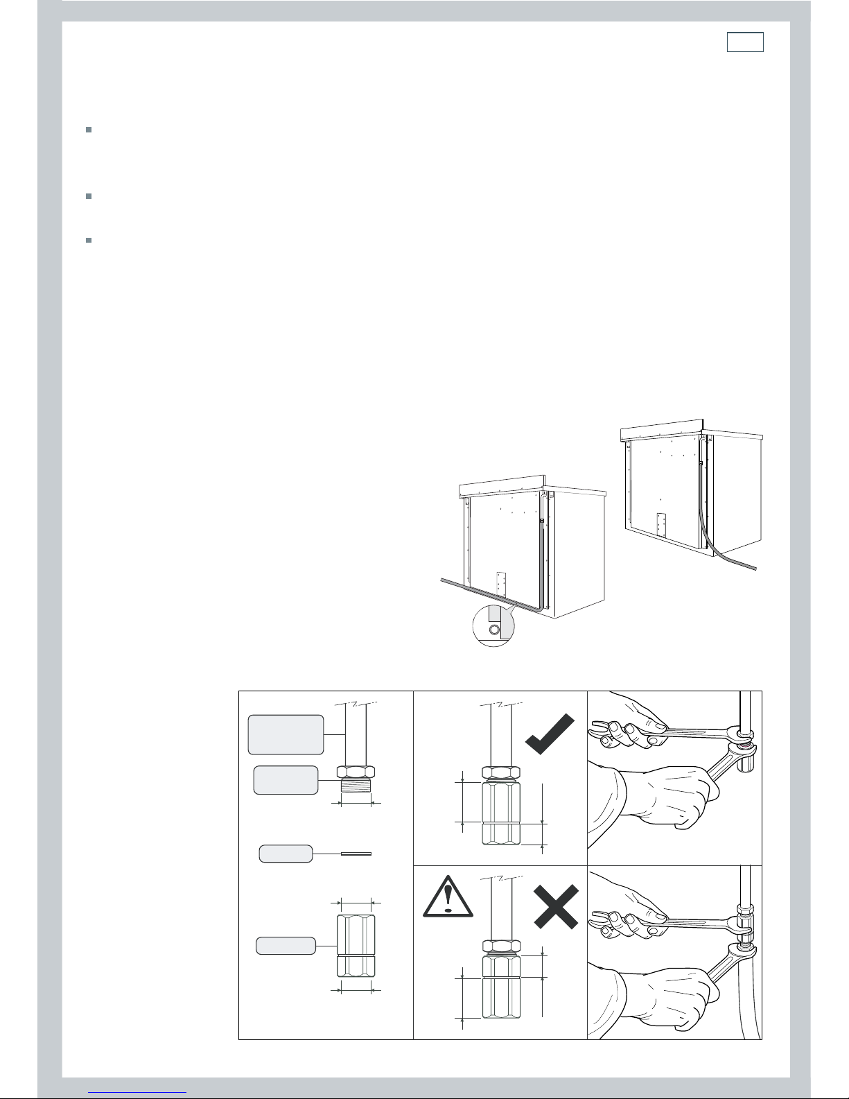
To connect the gas supply:
1
Fit the 1/2” BSP (female) connector (supplied with the cooker in a separate kit) to the gas inlet at
the rear of the cooker interposing the gasket. Check the correct positioning of the connector as
shown and always use two suitable spanners (Fig 6b).
2
Connect the gas supply to the gas inlet at the rear of the cooker. If the pipe has to cross the
cooker, it must be positioned under the protected area of the cooker (see Fig 6a)
3
To avoid damage to the appliance gas rail
inlet pipe tighten the fittings using two
suitable spanners (Fig. 6b).
4
Using a suitable leak detection fluid solution
(e.g. Rocol) check each gas connection one
at a time by brushing the solution over the
connection. The presence of bubbles will
indicate a leak. If there is a leak, tighten the
fitting and then recheck for leaks.
IMPORTANT!
Do not use a naked flame to test for leaks.
1/2” BSP (female)
1/2” G cylindrical
(ISO 228-1) male
1/2” G cylindrical
(ISO 228-1) female
20 mm
10 mm
20 mm
10 mm
Cooker manifold
Manifold male
pipe fitting
Gasket (*)
Connector (*)
(*) Supplied with the appliance in a separate kit.
Installation instructions
Fig. 6b
Fig. 6a
12
Installation instructions
C
D
A
B
Feeder cable section
“TYPE H05RR-F”
230V 3 x 2.5 mm2 (**)
(**) - Connection with wall
box connection.
PE
12345
N (L2)L1
230 V
Red or
Brown
(Live)
Black or
Blue
(Neutral)
Green
and
Yellow
(Earth)
23451
N(L2)
PE
L1
PE Earth
N Neutral
L Live
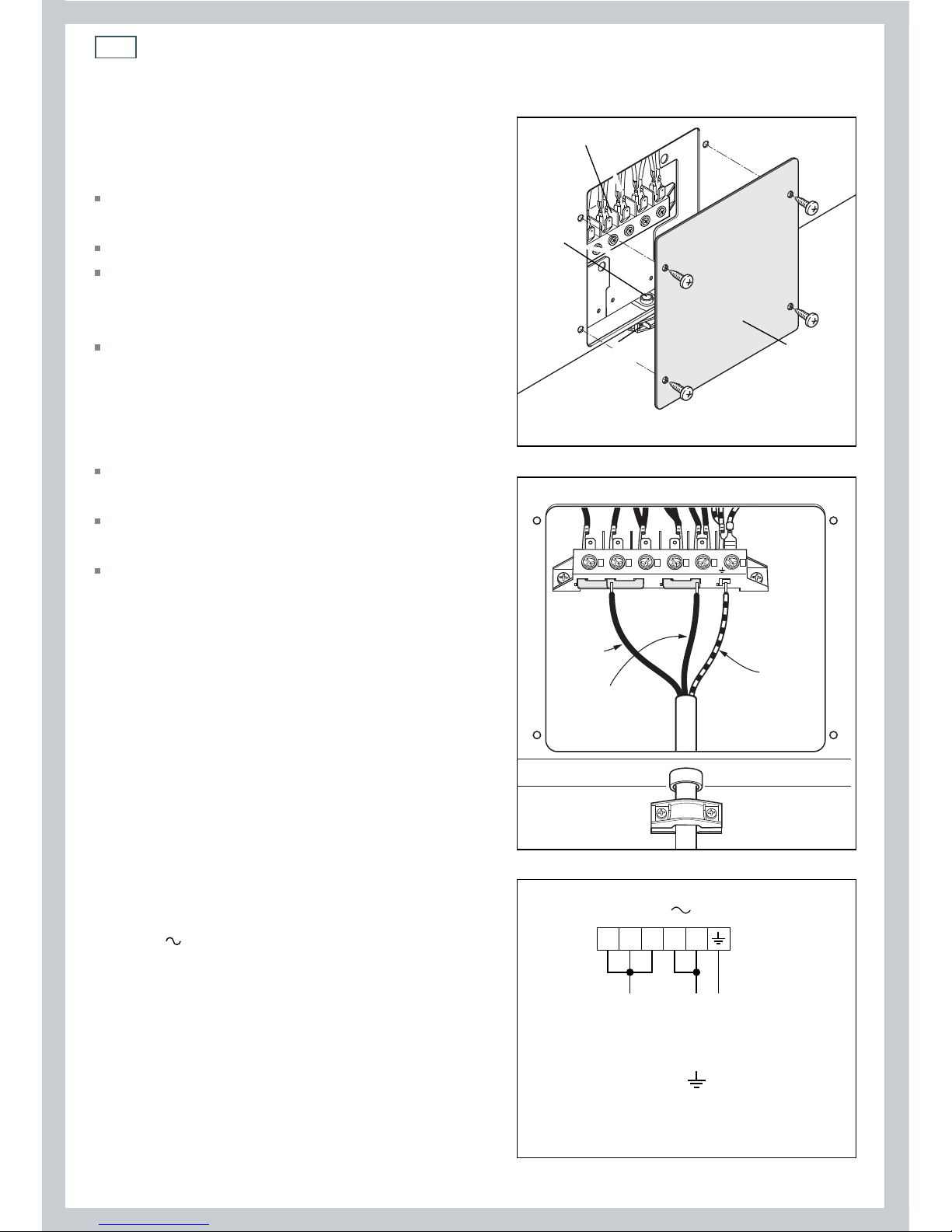
Connecting the feeder cable
To connect the feeder cable to the cooker:
Remove the four screws that hold shield “A”
behind the cooker.
Open the cable clamp “D” completely.
Check the position of the U bolts on the
terminal block “B” (Fig. 7a) according to the
diagram in Fig. 7b and Fig. 7c.
Insert the feeder cable into the cable clamp
“D”
and into the cable protector “C”. The
supply cable must be of a suitable size for
the current requirements of the appliance;
see ‘Feeder cable section’ following.
Connect the phase and earth cables to
terminal “B” according to Figs. 7b and 7c.
Pull the feeder cable and block it with the
cable clamp “D”.
Re-mount shield “A”.
Note: the earth conductor must be left
about 30 mm longer than the others.
Fig. 7a
Fig. 7b
Fig. 7c
Green
and
Yellow
(Earth)
Black
or Blue
(Neutral)
Red or
Brown
(Live)
13
Maintenance instructions
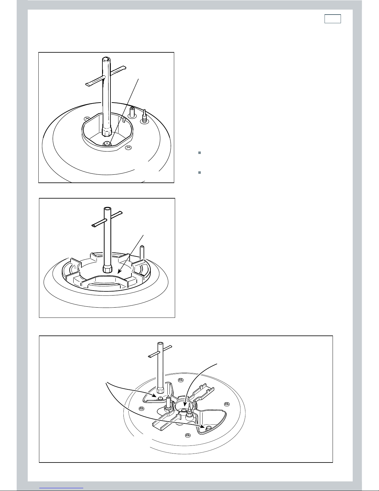
Replacing the burner injectors
If the injectors are not supplied, contact
the Fisher & Paykel Authorised Service
Centre.
Select the injectors to be replaced
according to the ‘Table for the choice of
injectors’.
To replace the injectors:
Remove pan supports and burners from
the cooktop.
Using a wrench, substitute the nozzle
injectors “J” (figs. 8a - 8b - 8c) with those
most suitable for the kind of gas used.
The burners are designed so that
adjustment of primary air is not required.
J
J
Dual burner
Triple ring wok
burner
Semi-rapid
burner
J
Injector for inner crown
Injectors for
outer crowns
Fig. 8a
Fig. 8b
Fig. 8c
J
 Loading...