

Page 1

FABRIC CARE SOLUTION
STACKED INSTALLATION
WH1160HG1, WH1160H1, DH9060HG1, DH9060H1, DH9060HLG1,
DH9060HL1, FC1260HG1, FC1260H1, FM2060SG1 and FM2060S1
models
INSTALLATION GUIDE
NZ AU
Page 2

COMPONENTS REQUIRED
TOOLS
Supplied
F 6mm Allen key
F Spanner (washer)
F Spanner (plinth)
Supplied and required
F 4x M10 bolts
F 2x plinth bolt hole covers
F 4x short stacking kit screws
F 2x long stacking kit screws
Not supplied
F Box cutter
F Phillips screwdriver
F Level
PARTS
Supplied and to be discarded
F 2x dryer front brackets
F 2x dryer rear brackets
F 2x dryer rear mounting screws
2
Page 3
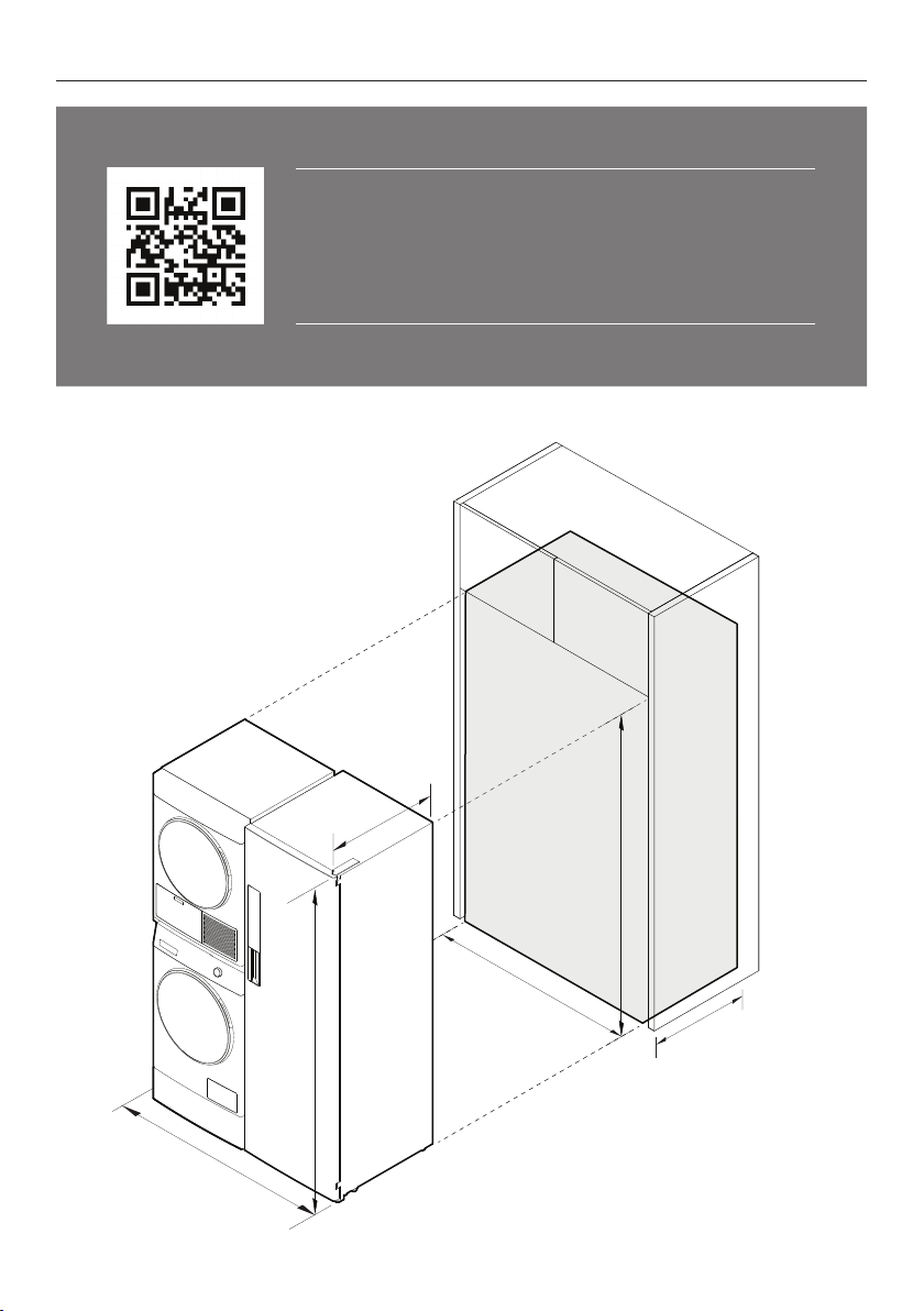
ACCESSING YOUR PRODUCT SPECIFICATIONS
For full product, cabinetry and service specifications, refer
to the Planning Guide. To access the Planning Guide, scan
the QR code or visit fisherpaykel.com/specify. Search by
appliance type, product name or model code.
1220
700
1920
1260
700
1900
3
Page 4
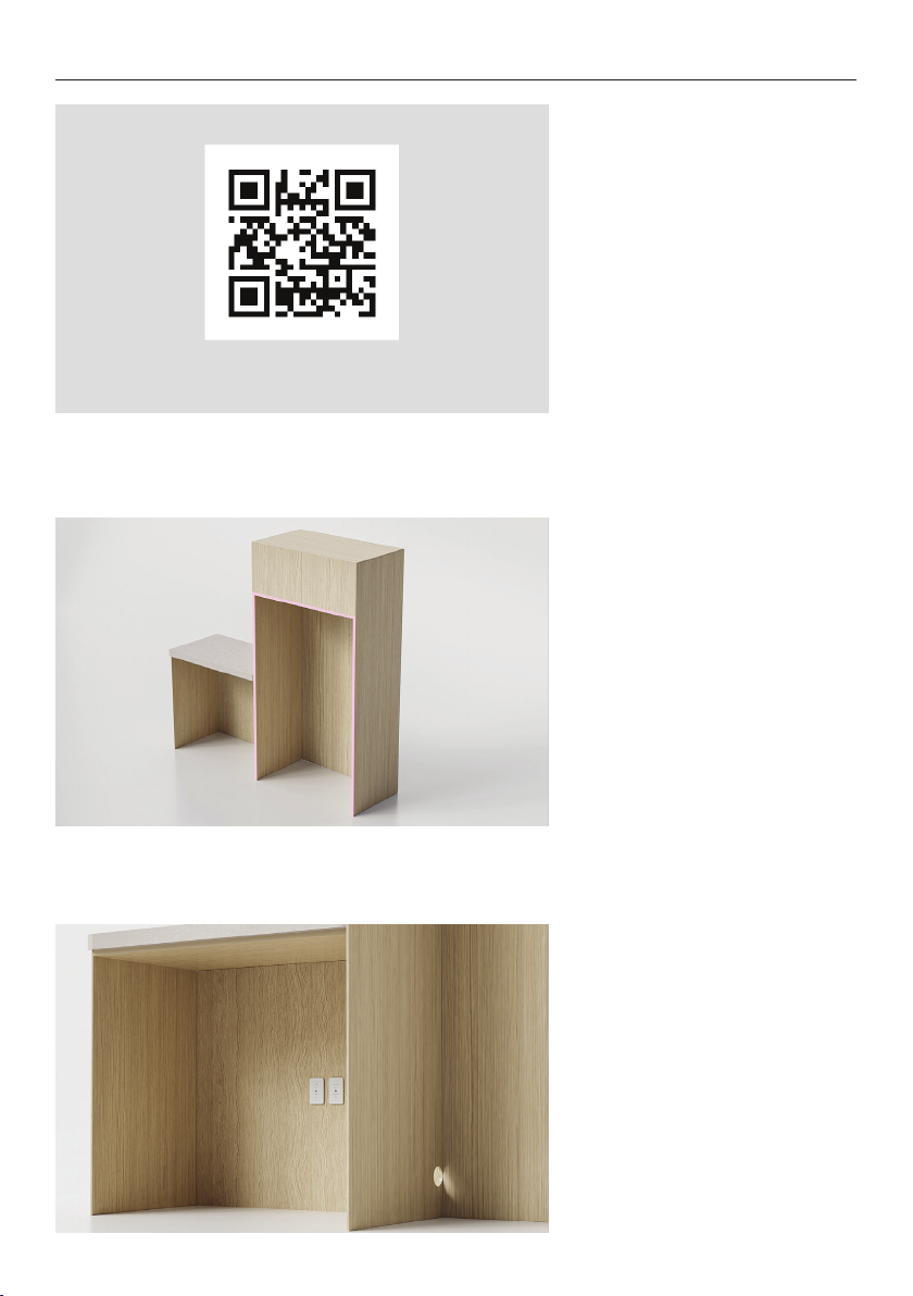
PRIOR TO INSTALLATION
fisherpaykel.com/specify
1. Ensure cabinetry and
servicing specifications have
been met and clearances have
been considered.
Refer to the Planning Guide for
details.
2. Ensure floor is level and clear
and a finished return has been
created.
3. Ensure power will remain
accessible following install to
allow access for any future
product maintenance.
Service holes should be smooth
with gromets installed where
required.
Refer to the services section
of the Planning Guide for more
details.
4
Page 5
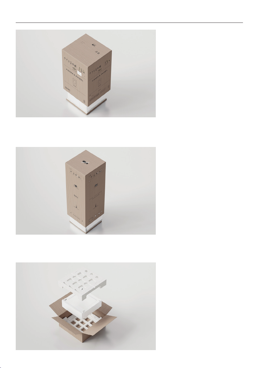
UNPACK ALL PRODUCTS
Washer and Dryer:
Cut the straps and the line
printed on the top of the
carton. Lift to remove. Discard
braces and corner posts.
Remove any packaging and
accessories from the drum and
base packer.
Dispose of packaging
responsibly.
Fabric Care Cabinet:
Cut the straps and the line
printed on the back of the
carton. Cut to the nearest
corner and remove sleeve.
Discard braces, corner posts
and sleeve.
Remove packaging and
accessories from inside cabinet.
Dispose of packaging
responsibly.
Plinth:
Cut the straps and tape to
open the carton from the top.
Remove the EPS cap before
lifting the plinth out.
Set cardboard aside for later
use. Ensure accessories are
removed from the EPS cap
before discarding EPS and
rubber spacers responsibly.
5
Page 6
UNPACK ALL PRODUCTS
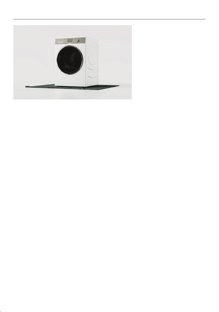
Protect flooring before
positioning products as close
to the installation location
as possible, ensuring enough
working room is left available.
6
Page 7
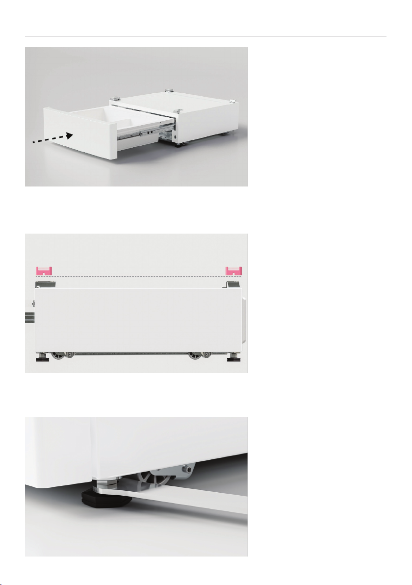
LEVEL PLINTH
1. Push the front of the plinth
to open. Remove the divider
before closing the drawer.
2. Place the plinth in its final
install location. Adjust the feet
using the supplied spanner until
the washer is level front to back
and corner to corner.
3. Using the spanner provided,
tighten the lock nuts against
the base of the plinth to lock
the feet in position.
Recheck that the plinth is level,
front to back and side to side.
Once level, move the plinth to
an accessible location to allow
washer/dryer to be installed.
7
Page 8
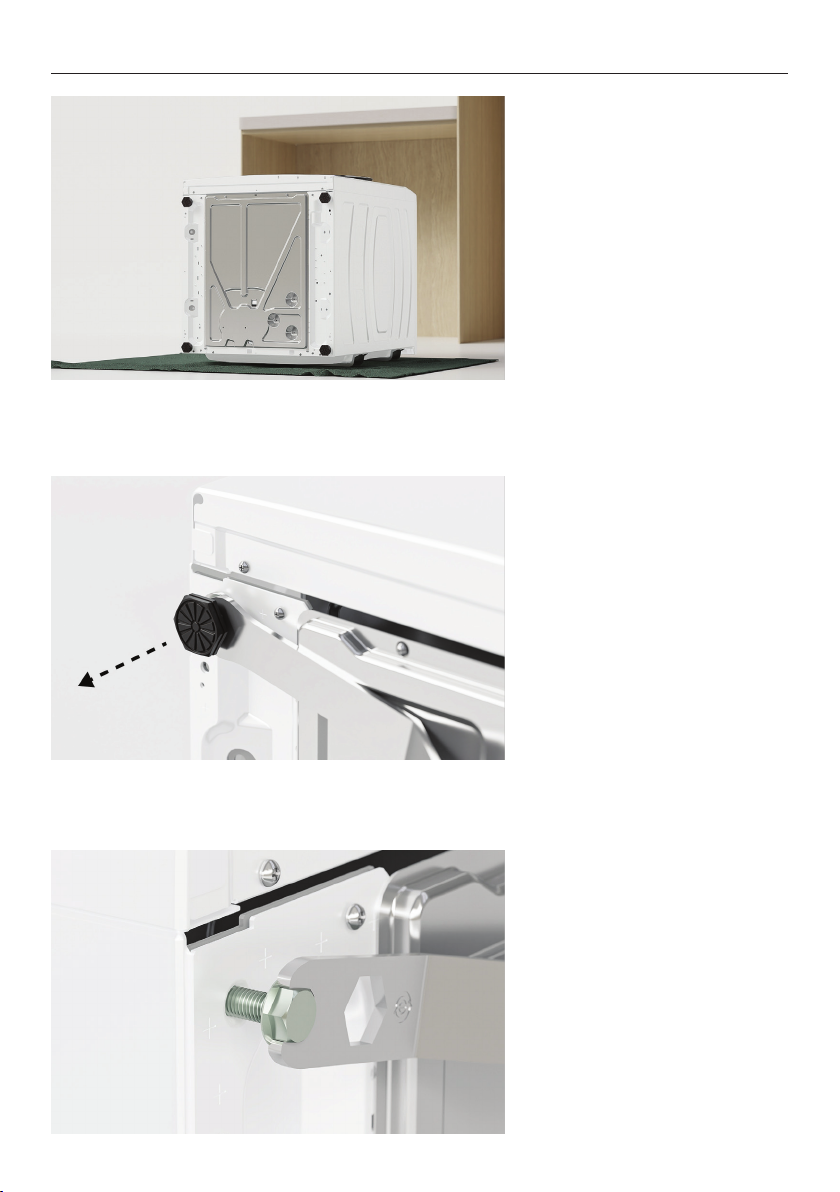
FIT WASHER TO PLINTH
1. Tilt the washer back onto a
protected surface such as the
plinth carton. Ensure cords
and hoses are not crushed. For
new products, we recommend
keeping the transit bolts fitted
during this step.
2. Unwind feet using the
supplied spanner to remove.
3. Partially fit the four M10 bolts
supplied with the storage plinth
to the washer.
8
Page 9
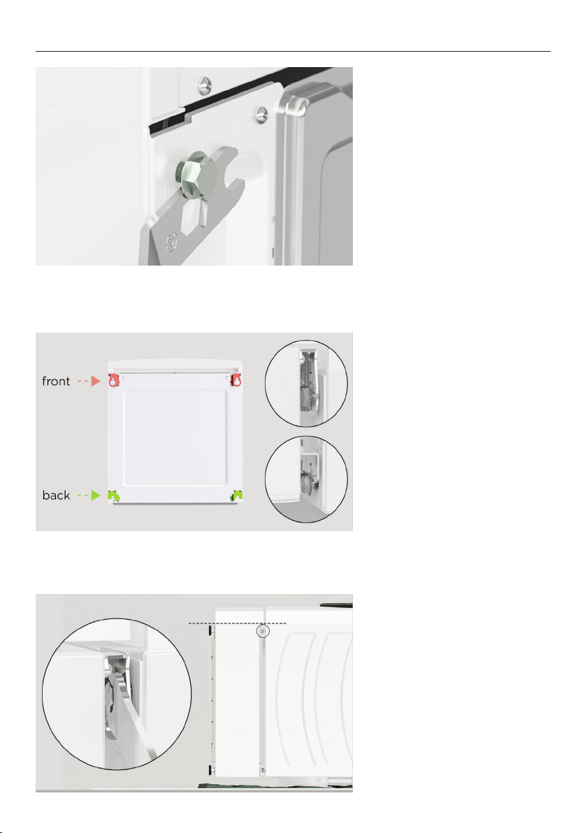
FIT WASHER TO PLINTH
4. Using the spanner provided
as a spacer, ensure a 4mm gap
is left between the bolt head
and the chassis.
5. Align all four brackets to the
M10 bolts on the washer and
slot into place.
6. Ensure plinth is aligned on
both sides as shown before
tightening the front bolts with
the supplied spanner.
9
Page 10
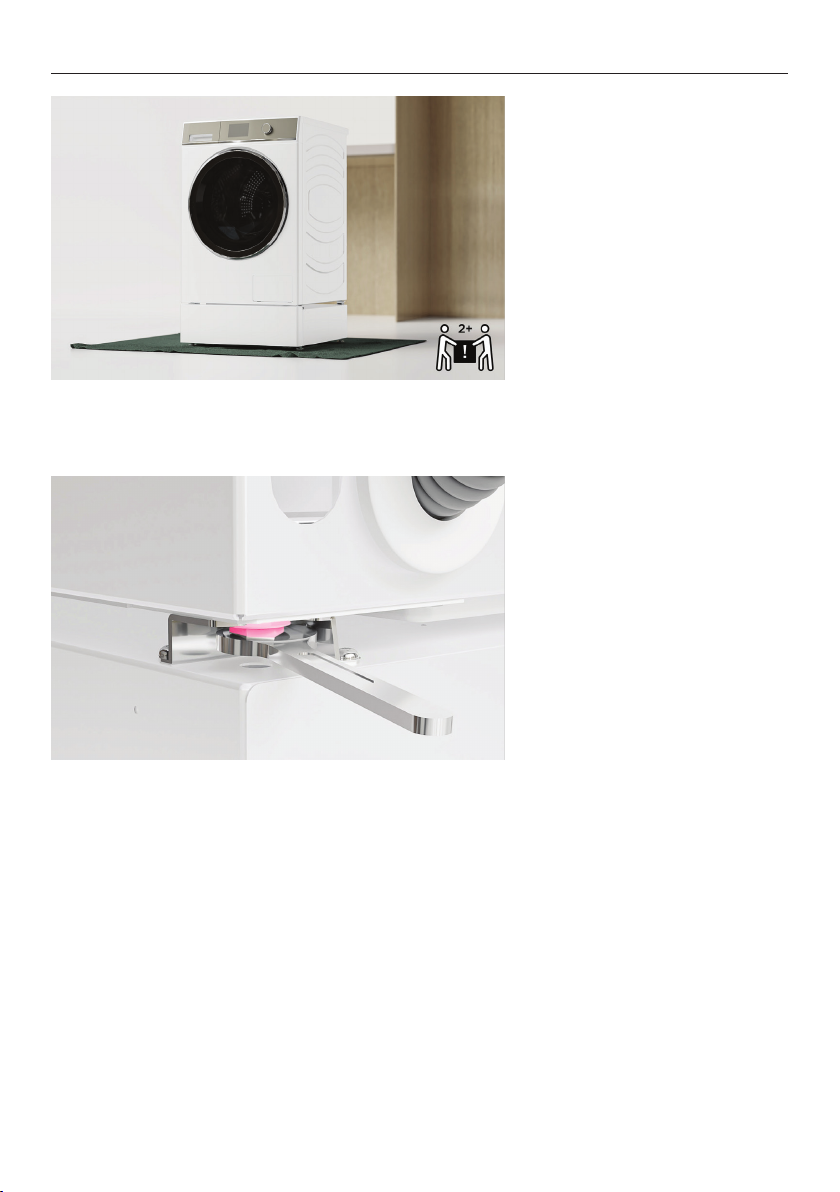
FIT WASHER TO PLINTH
7. Lift the washer upright,
avoiding lifting from the lid.
Take care as storage drawer
may open.
8. Tighten the rear bolts.
10
Page 11
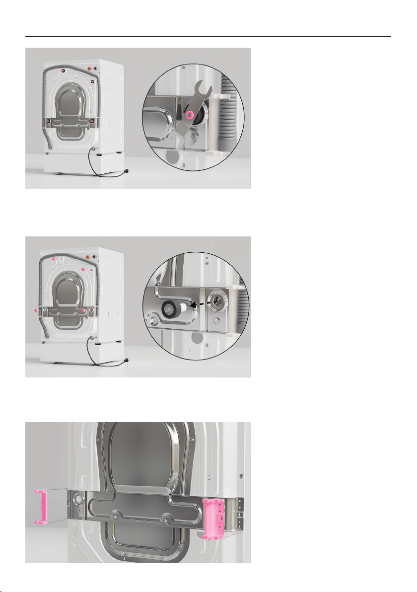
REMOVE WASHER TRANSIT BOLTS
1. Using the supplied spanner,
remove all four transit bolts
from the back of the washer.
2. Pull the rubber grommets
and spacers outwards to
remove.
3. Using a Phillips screwdriver,
remove the two side brackets.
11
Page 12
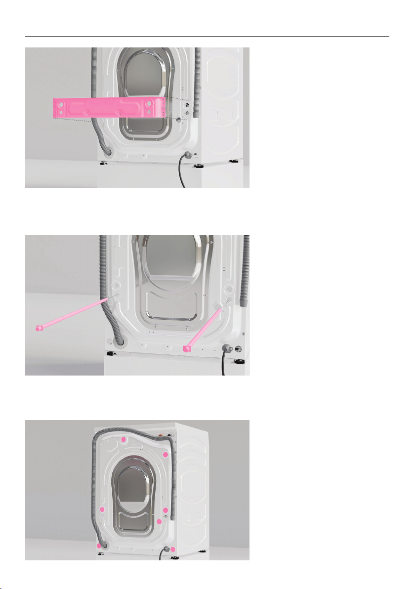
REMOVE WASHER TRANSIT BOLTS
4. Remove and discard the
braces.
5. Pull the two transit rods
outwards to remove.
Set aside for future use.
6. Cover the transit bolt holes
using the supplied plugs.
12
Page 13
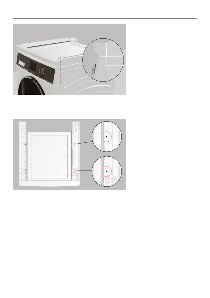
INSTALL STACKING KIT TO WASHER
1. Align the front corner of the
stacking kit to the washer.
2. Secure the stacking kit to
the washer using the four
supplied short screws in the
marked locations. If using a
drill, the lowest torque setting
is recommended.
13
Page 14
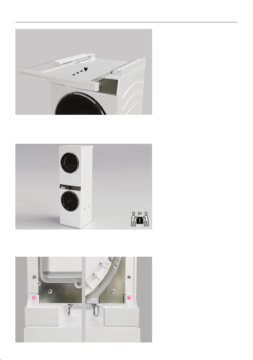
INSTALL DRYER TO STACKING KIT
1. Ensure stacking kit shelf is
pushed all the way in and dryer
feet have been fully wound in.
2. Lift dryer onto the stacking
kit ensuring all four feet rest in
the slots.
3. Using the two supplied long
screws, secure the dryer to the
stacking kit at the rear.
14
Page 15
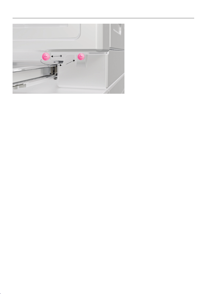
INSTALL DRYER TO STACKING KIT
4. Remove the two screws from
the front of the dryer and refit
through the stacking kit.
15
Page 16
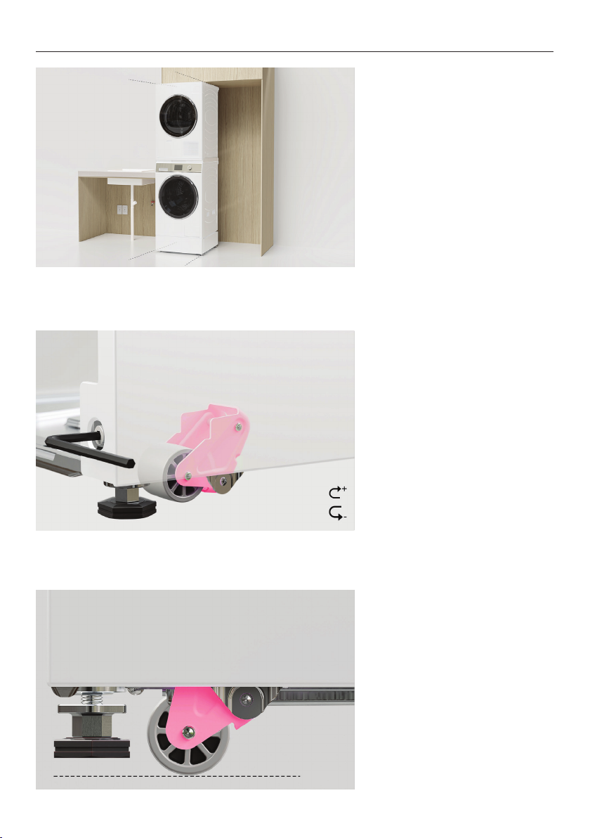
LEVEL PRODUCT SET
1. We recommend levelling and
installing stacked products
into alcove before fabric care
cabinet.
2. Partially roll stacked
products into alcove and check
alignment. To do this, use the
supplied 6mm hex key, rotate
clockwise to lower both sets
of wheels via the adjustment
screws.
3. Ensure all feet are raised
off the floor before rolling
the plinth to the final install
location.
Floor
16
Page 17
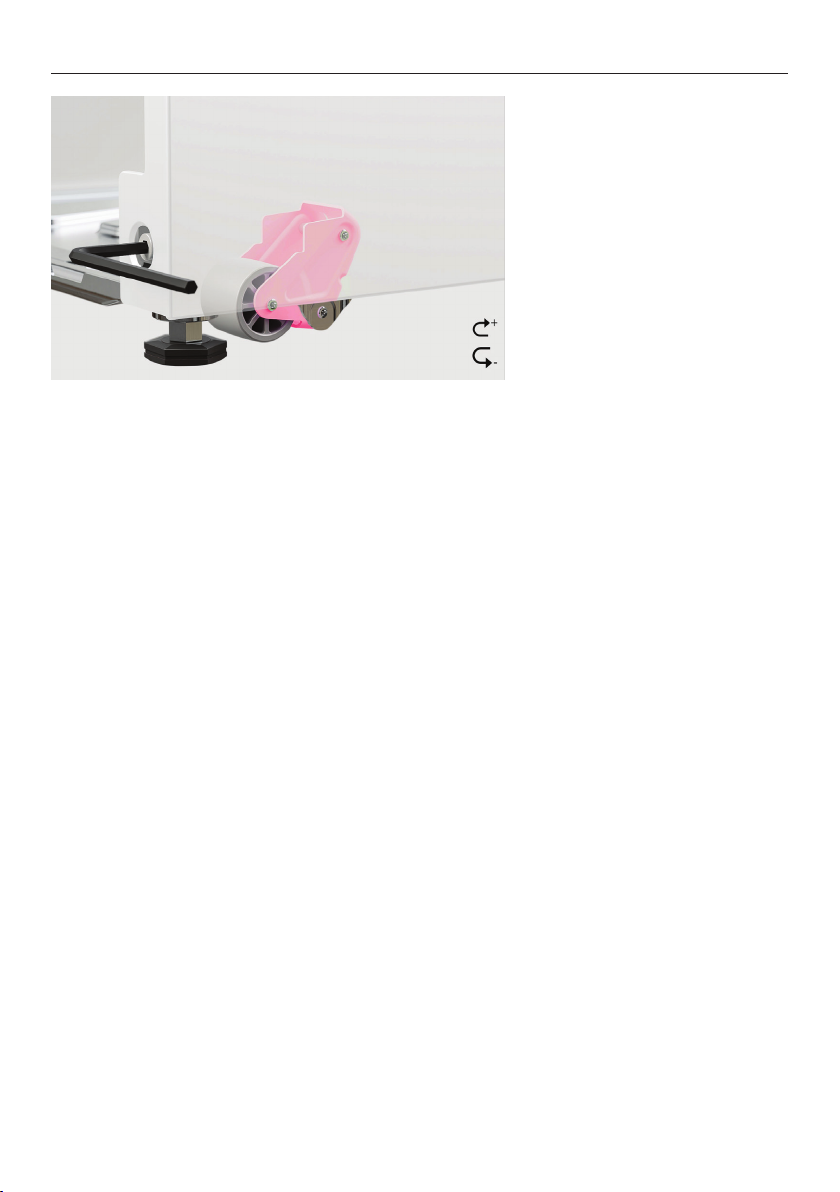
LEVEL PRODUCT SET
4. Using the supplied 6mm hex
key, rotate counter-clockwise
to raise both sets of wheels via
the adjustment screws.
17
Page 18
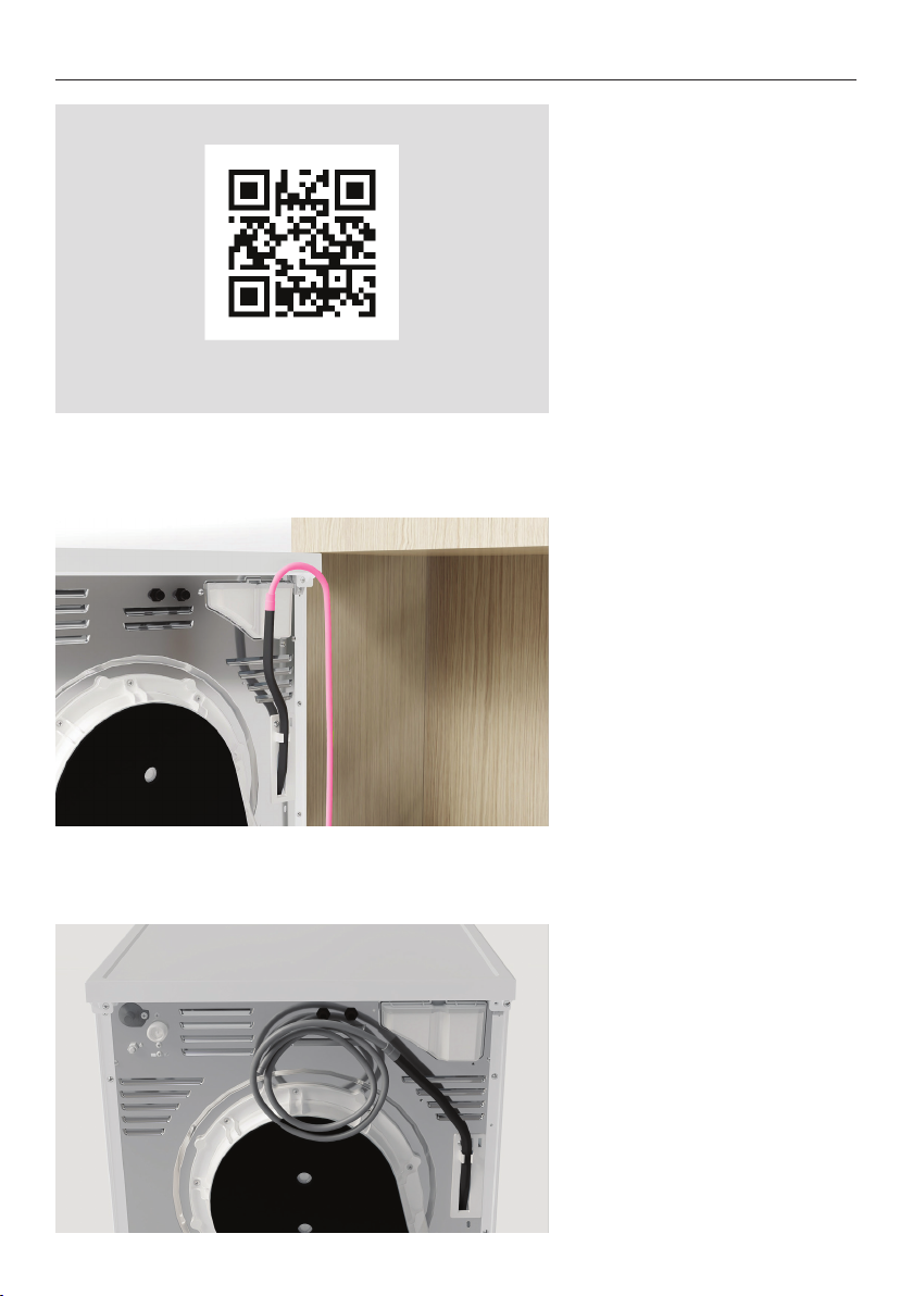
CONNECT CABLES AND HOSES
fisherpaykel.com/specify
1. Refer to the Planning Guide
for service information.
2. Optional:
For displayed dryers, fit the
drain hose extension if dryer
can be plumbed.
3. Display-free models:
Display-free models must be
plumbed.
Unwind the drain hose.
Plumbed installations:
Ensure hose can be connected
to a drain.
18
Page 19
CONNECT CABLES AND HOSES
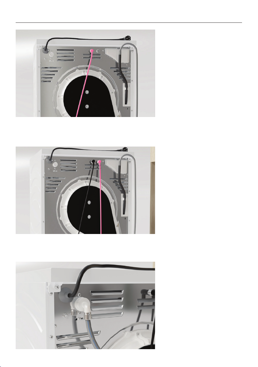
4. Remove caps from washer
and dryer before fitting one of
the communication cables.
Connect the washer and dryer
via the communication cable.
5. Connect fabric care cabinet
communication cable to dryer.
6. Connect the angled end of
the cold water hose (supplied
with washer) to the dryer.
19
Page 20
CONNECT CABLES AND HOSES
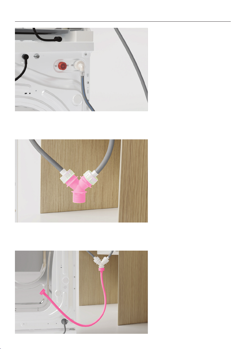
7. Connect the angled end of
the short hose (supplied with
dryer) to the cold water inlet
on the washer.
8. Connect both hoses to the
top of the Y join supplied with
the dryer.
20
9. Connect the straight hose to
the bottom of the Y join.
Page 21
CONNECT CABLES AND HOSES
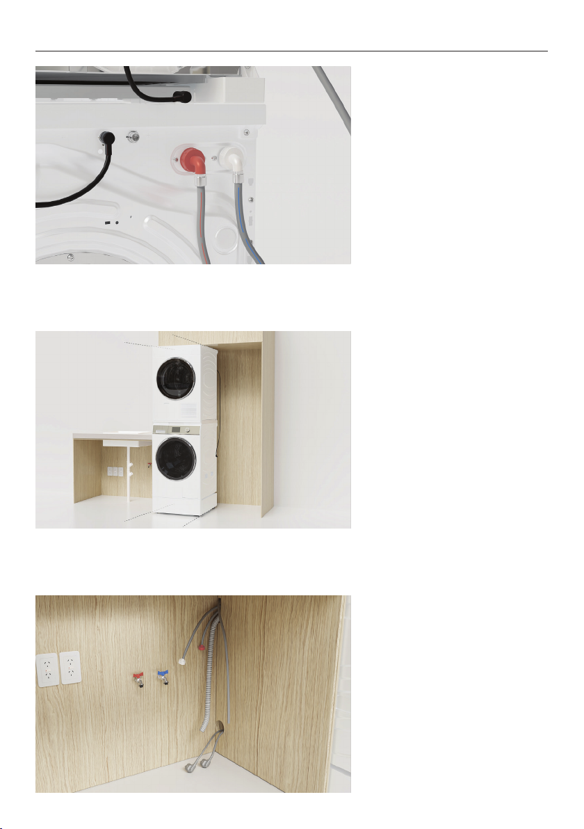
10. Connect the angled end of
hot hose to the orange outlet
on the washer. If hot hose is
not required, install a blanking
cap.
11. Partially roll products into
the alcove.
Ensure fabric care cabinet
communication cable is
accessible from the rear of the
dryer.
12. Route the power cables and
hoses through service holes.
Ensure power will remain
accessible following install to
allow access for any future
product maintenance.
21
Page 22
20mm
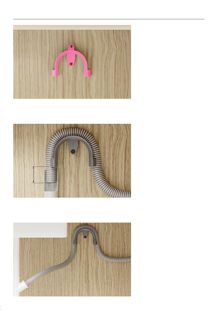
CONNECT CABLES AND HOSES
13. Install the drain hose guide
to the back wall.
Refer to the planning guide for
placement details.
14A. Standpipe Installations:
Route the drain hose through
the guide and place into the
standpipe.
Ensure a maximum of 20mm of
the hose rests in the standpipe.
22
14B. Spigot Installations:
Drill out blanking insert from
the spigot.
Route the drain hose through
the guide and place into the
spigot. Secure using a hose
clamp.
Page 23
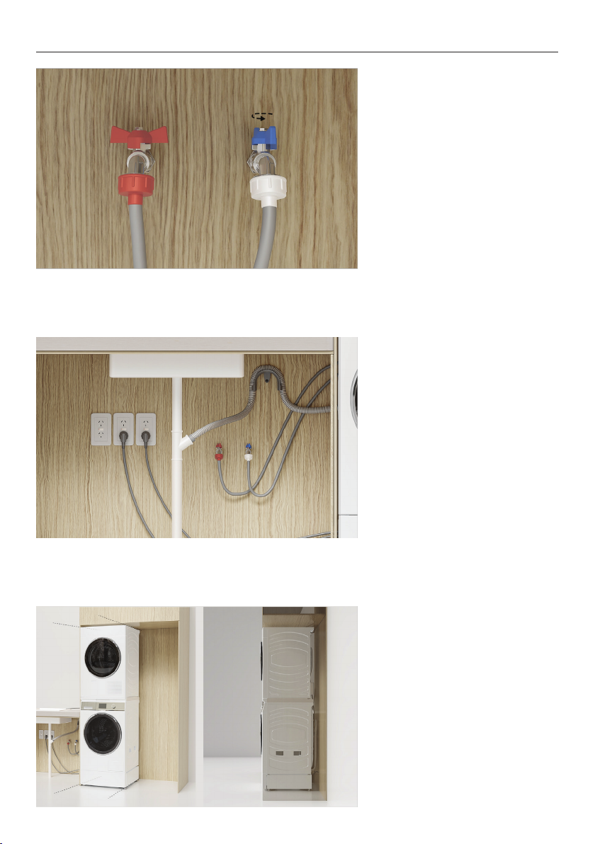
CONNECT CABLES AND HOSES
15. Connect hoses to taps
before turning on. Check for
leaks at all connection points.
16. Connect the power cables
and check products are
powered on and are connected.
17. Roll products into the
alcove.
Take care not to damage hoses
or cords.
23
Page 24
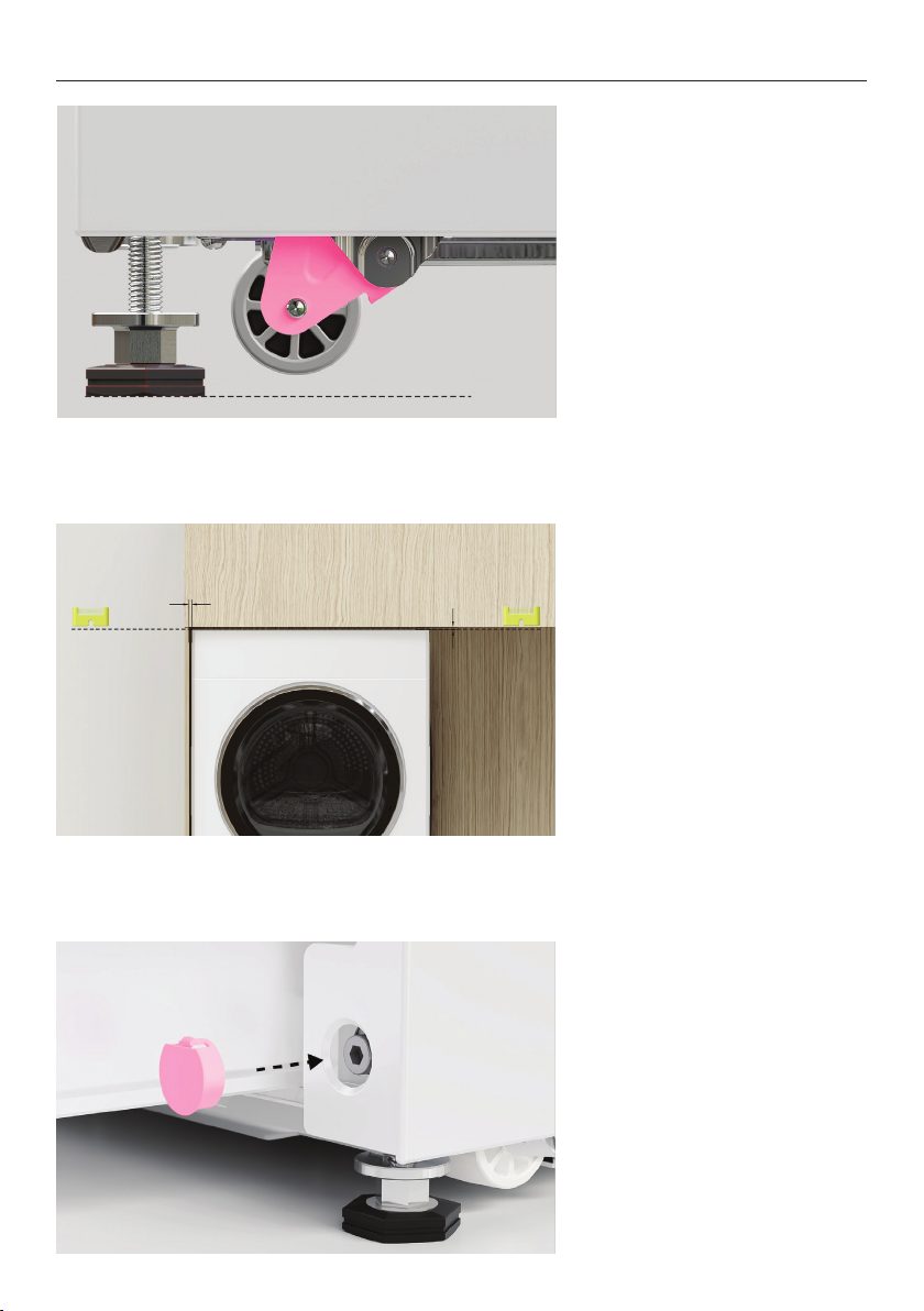
CONNECT CABLES AND HOSES
18. Turn the adjustment screw
counter-clockwise to retract
the wheels. Ensure the wheels
are fully raised off the floor.
Floor
19. Check alignment and
ensure required clearances are
maintained. Adjust as required.
24
20. Once adjustment is
complete, fit the plinth bolt
hole covers.
Page 25
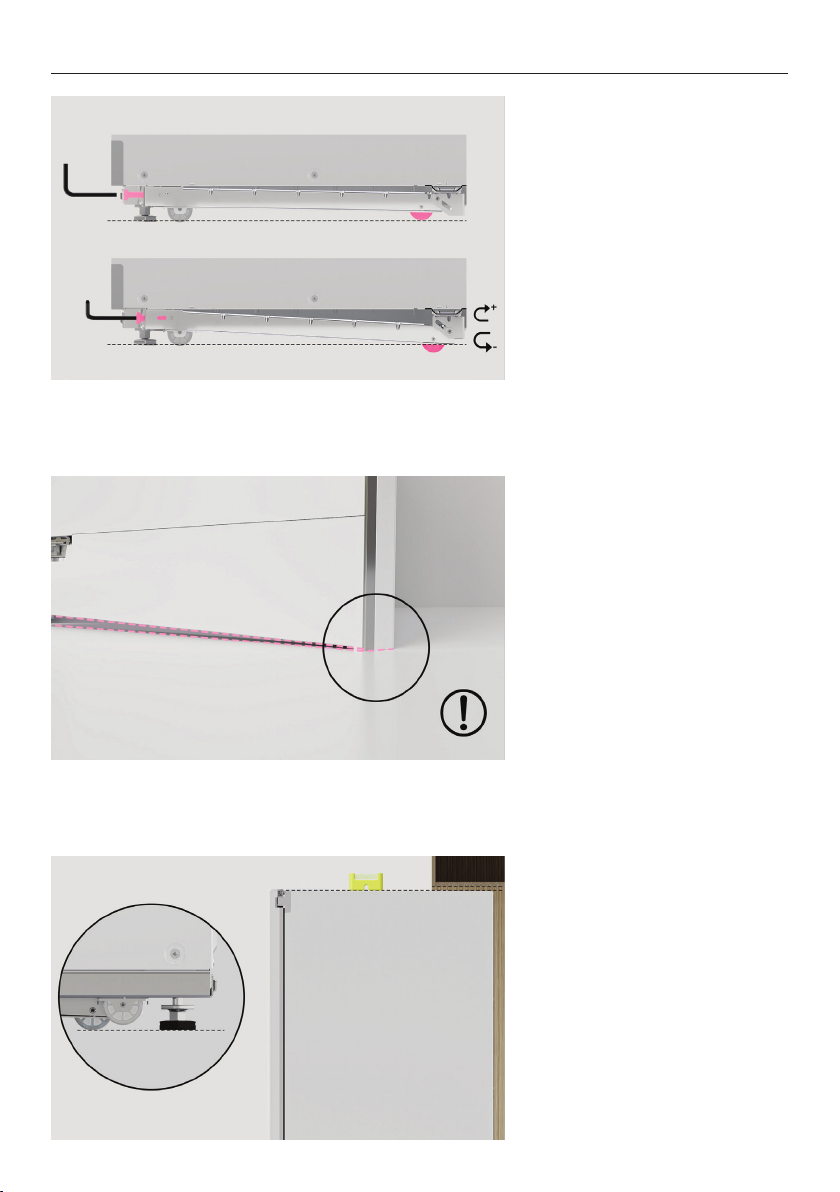
INSTALL FABRIC CARE CABINET
1. Open the cabinet door and
lower the rear wheel using the
supplied Allen key.
Rotate clockwise to lower the
wheel and counter-clockwise
to raise.
2. When adjusting the wheel,
ensure front of the door
doesn’t damage the floor.
3. Prior to installing in alcove,
adjust rear feet to the desired
height
Ensure all clearances are
maintained.
25
Page 26
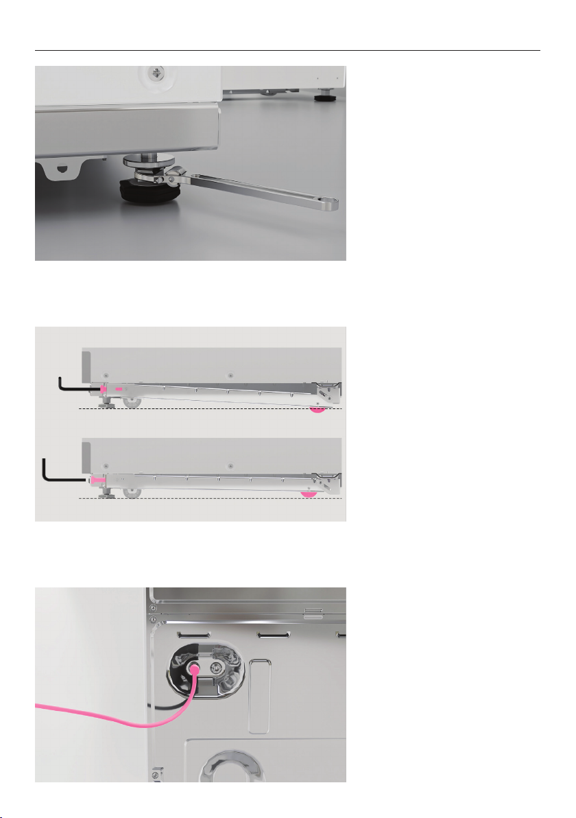
INSTALL FABRIC CARE CABINET
4. Tighten the locking nuts up
to the base of the cabinet to
lock feet in position.
5. Lower the rear wheel to
achieve clearance between rear
feet and floor.
When adjusting the wheel,
ensure front of the door
doesn’t damage the floor.
26
6. Connect communication and
power cables.
Page 27
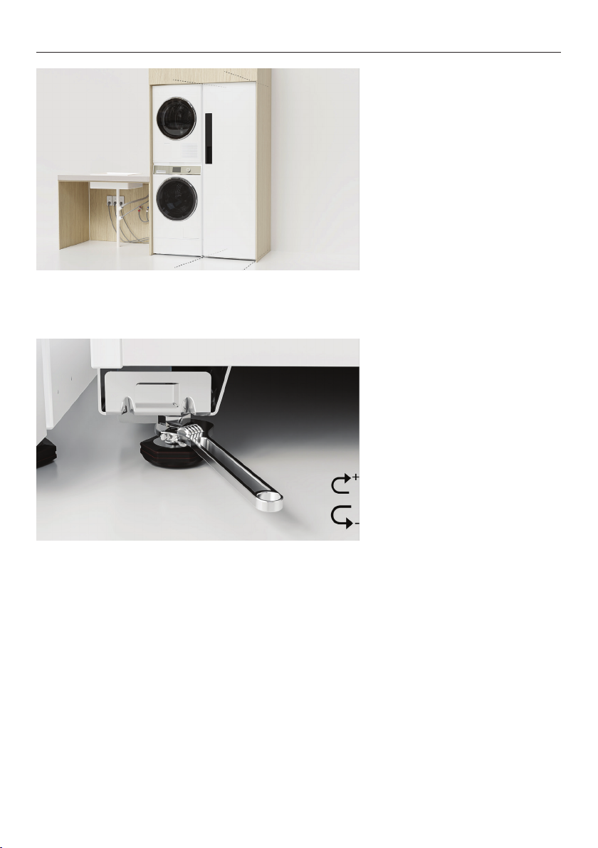
INSTALL FABRIC CARE CABINET
7. Push cabinet into cavity
taking care not to damage
cords.
Rotate the rear wheel
adjustment screw anticlockwise to place the full
cabinet weight onto feet.
Ensure rear corners are level
and set to the desired height.
8. With cabinet in the final
position, unscrew front levelling
feet using the provided
spanner. Re-check clearances
and alignment before
tightening the locking nuts up
to the base of the cabinet to
lock the feet into position.
27
Page 28
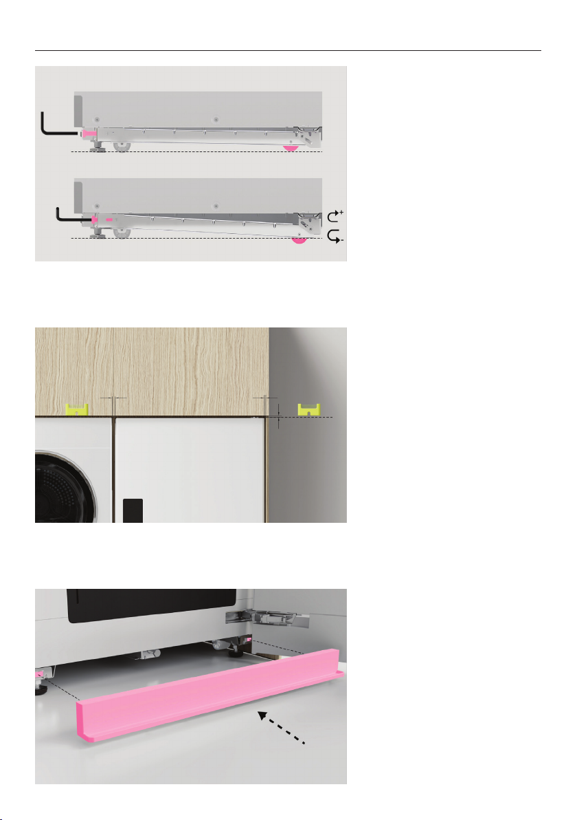
INSTALL FABRIC CARE CABINET
9. Ensure cabinet is resting on
all four feet and all wheels have
been raised.
10. Check final alignment and
ensure required clearances are
maintained.
Adjust as required.
28
11. Clip drip tray into position.
Page 29

INSTALLER CHECKLIST
Complete and keep for safe reference:
Model
Serial no.
Purchase date
Purchaser
Dealer address
Installer’s name
Installer’s signature
Installation company
Installation date
29
Page 30

FISHERPAYKEL.COM
© Fisher & Paykel Appliances 2023. All rights reserved.
The models shown in this guide may not be available in all markets
The product specifications in this guide apply to the specific products and
models described at the date of issue. Under our policy of continuous product
improvement, these specifications may change at any time.
For current details about model and specification availability in your country,
please go to our website or contact your local Fisher&Paykel dealer.
and are subject to change at any time.
41190A 07.2
 Loading...