

Fisher & Paykel DOUBLE DISHDRAWER DD60DDF Series Installation Manual

DOUBLE DISHDRAWER™ DISHWASHER
DD60DDF models
INSTALLATION GUIDE
NZ AU GB IE SG
591384C 05.19

1 SAFETY AND WARNINGS
IMPORTANT SAFETY INSTRUCTIONS
!
WARNING!
Electrical shock hazard
Before installing the dishwasher, remove the
house fuse or open the circuit breaker.
This appliance must be earthed. In the event
of a malfunction or breakdown, earthing will
reduce the risk of electric shock by providing
a path of least resistance for electric current.
This appliance is equipped with a cord having
an equipment-earthing conductor and an
earthing plug. The plug must be plugged into
an appropriate outlet that is installed and
earthed in accordance with all local codes
and ordinances.
WARNING — Improper connection of the
equipment-earthing conductor can result in a
risk of electric shock. Check with a qualified
electrician or service representative if you
are in doubt as to whether the appliance is
properly earthed.
Do not modify the power supply plug
provided with the appliance — if it will not fit
the outlet, have a proper outlet installed by a
qualified electrician. Do not use an extension
cord, adapter plug or multiple outlet box.
Failure to follow this advice may result in
electrical shock or death.
!
WARNING!
Cut Hazard
Take care — panel edges are sharp.
Failure to use caution could result in injury
or cuts.
1
O
Installation of this dishwasher requires basic
mechanical and electrical skills.
O
Be sure to leave these Instructions with the Customer.
O
Installation must comply with your local building and
electricity regulations.
O
At the completion of the dishwasher installation,
the Installer must perform the Final Checklist.
O
Remove all packaging materials supplied with
the dishwasher.
O
This dishwasher is manufactured for indoor use only.
O
Ensure all water connections are turned OFF.
It is the responsibility of the plumber and electrician
to ensure that each installation complies with all
Codes and Regulations.
O
The dishwasher MUST be installed to allow for future
removal from the enclosure if service is required.
O
The switched power outlet must be outside
the dishwasher cavity, so that it is accessible
after installation.
O
Care should be taken when the appliance is installed
or removed to reduce the likelihood of damage to the
power supply cord and hoses.
O
If the dishwasher is to be relocated from one
installation to another it must be kept upright to
avoid damage from water spillage.
O
Make sure only new hoses are used for connection
(supplied with the dishwasher). Old hoses should not
be reused.
O
Failure to install the dishwasher correctly could
invalidate any warranty or liability claims.
O
If the product is installed in a motor vehicle, boat or
similar mobile facility, you must bring the vehicle,
boat or mobile facility containing the product to
the service shop at your expense or pay the service
technician’s travel to the location of the product.
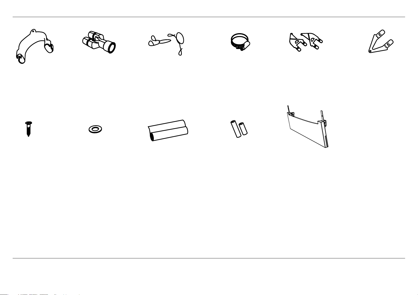
2 PARTS SUPPLIED
Drain hose
support (1)
Phillips
16 mm
screws (9)
Dishdrawer™ installation overview
This video provides an overview of what is needed to install a DishDrawer™. It is intended as an overview only
of the installation process and is not intended to be used as a guide on how to install a DishDrawer™ yourself.
https://vimeo.com/325297597
Drain hose
joiner (1)
inlet hose (1)
(comes already fitted)
Wire clip (2)
(for securing
Drain hose joiner)
Moisture protection
tape (1)
(to prevent moisture
damage to cabinetry)
Clamp (1)
(for securing
Drain hose joiner)
Hexagonal
socket for feet
adjustment (2)
(long & short)
Side mounting
bracket kit
(A and B) (2)
OPTIONAL
Prefinished toekick (1) Rubber washer for
Top
mounting
brackets (2)
OPTIONAL
If the Drain hoses supplied are not long enough to reach your services, you must use a Drain Hose Extension Kit P/N 525798 which will extend the drain hoses by 3.6 m.
The kit is available from the nearest Fisher & Paykel Authorised Service Centre or our website.
IMPORTANT!
SAVE THESE INSTRUCTIONS
The models shown in this installation guide may not be available in all markets and are subject to change at any time. For current details about model and specification availability in your country,
go to our website fisherpaykel.com or contact your local Fisher & Paykel dealer.
2
B
D
O
N
F
C
H
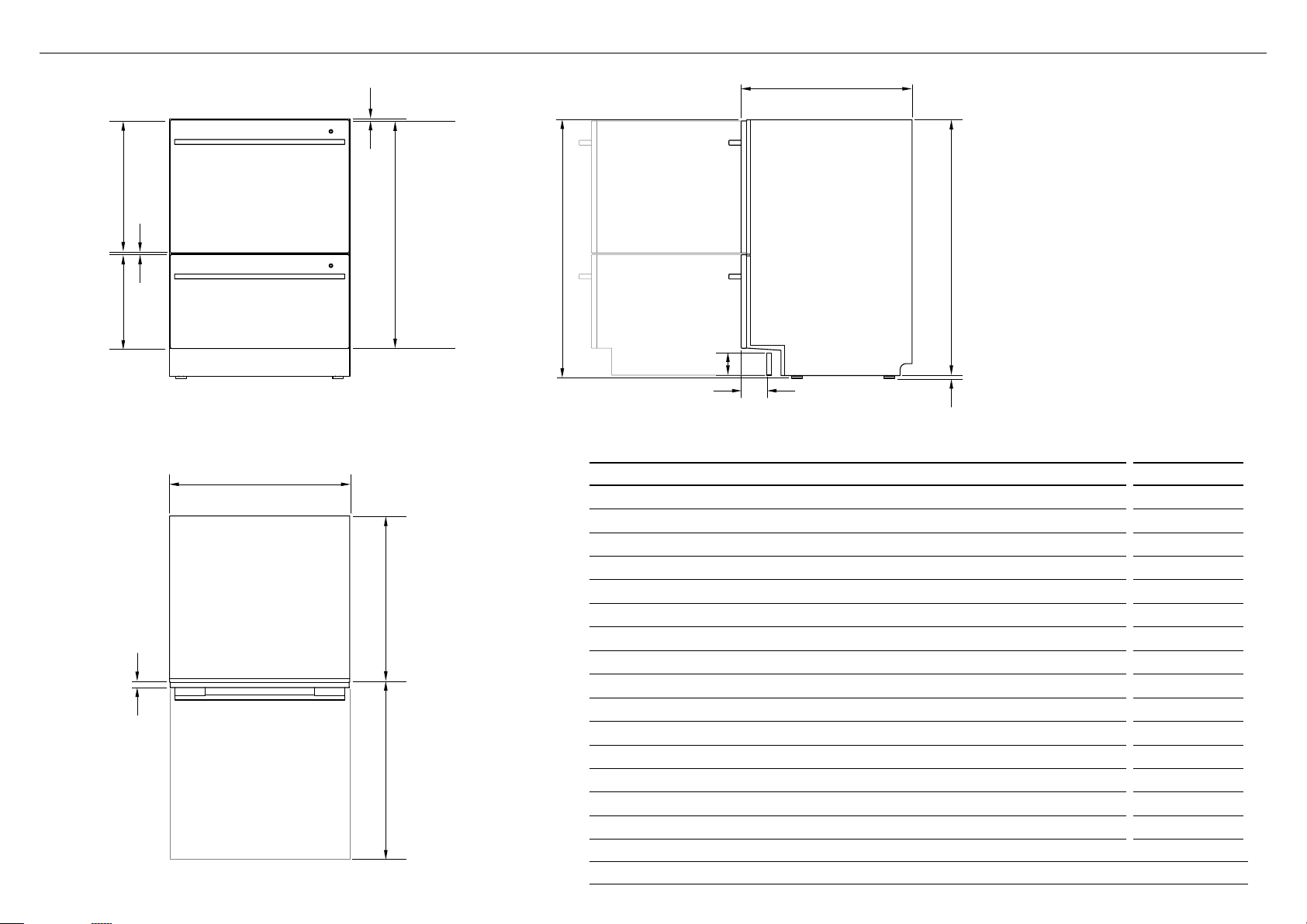
3 PRODUCT DIMENSIONS
J
K
G
A
I
L
PROFILEFRONT
M
DD60DDF
PRODUCT DIMENSIONS MM
1
3
820-880
E
PLAN
Overall height of product
A
Overall width of product 599
B
Overall depth of product 573
C
Depth of chassis (to back of front drawer panel) 553
D
Depth of drawer front panel 20
E
Height of chassis
F
Height of drawer front panels 717
G
Height of upper drawer front panel 398
H
Height of lower drawer front panel 312
I
Height from top of drawer front panel to top of chassis 2
J
Ventilation gap between drawer front panels 8
K
Height of toekick (customisable) 70-120
L
Depth from front of drawer panel to front of toekick (adjustable)
M
Height of levelling feet (adjustable) 9-69
N
Maximum extension of drawer 547
O
1
includes 2mm high bracket slots2 depending on adjustment of levelling feet
3
adjustable to match toekick recess on adjoining cabinetry
1
3
2
811
38-54
2
Bracket slots
R
Q
P
S
T
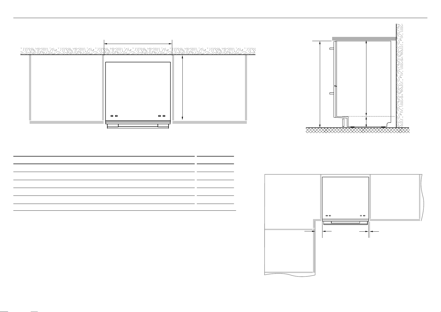
4 CABINETRY DIMENSIONS
PLAN
DD60DDF
CABINETRY DIMENSIONS MM
Inside height of cavity* min. 820
P
Inside width of cavity 600
Q
Inside depth of cavity min. 560
R
Recommended height of adjacent cabinet space 720
S
Height of toekick space* 100-160
T
* depending on adjustment of levelling feet
PROFILE
Minimum clearances from adjacent cabinetry
min. 13 mm
clearance
from a corner
cupboard
min. 2 mm
clearance
to adjacent
cupboard door
4
COUNTERTOP
10 mm
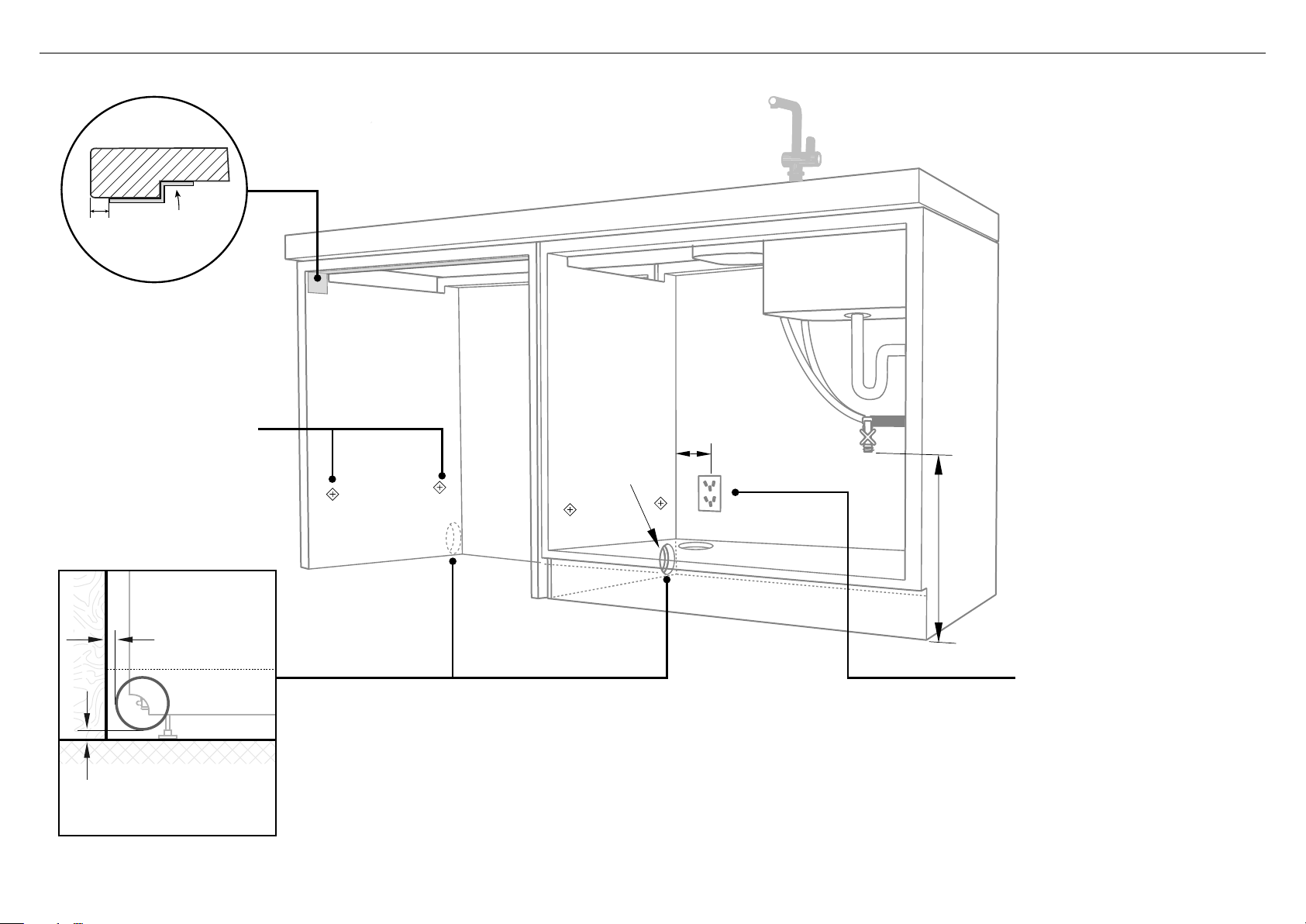
Moisture
protection tape
must be applied.
These marks indicate formed
bracket screw locations, if
securing by drawer removal.
If there is no side partition, you
can construct timber bracing
as something to secure into.
WARNING!
Incorrect placement of the hole
will result in damage to hoses.
Max 5mm
Max distance
between hole edge
and rear inner face
5 CAVITY PREPARATION
max. 450mm
Ø 57mm
Service Holes
Can be located either side of dishwasher, close to the rear face and
the floor, as illustrated, for access to the water supply and drain.
min. (200mm
IMPORTANT!
The power outlet must be located
in a cabinet adjacent to the
dishwasher cavity.
220-240 VAC min. 9.5 A
Water Connection
Recommended COLD
(Maximum 60°C).
3/4“ BSP (GB20) to
suit flat washer.
Water Pressure
Water softener models
Max. 1 MPa (145 psi)
Min. 0.1 MPa (14.5 psi)
Models without water softener
Max. 1 MPa (145 psi)
Min. 0.03 MPa (4.3 psi)
Kosher requirements
Drains will need to be
separated to satisfy
kosher requirements.
We suggest you confirm
acceptability with your
local rabbi in respect to
kosher installations.
Max 10mm
Max distance between
hole edge and floor
5
O
If the hole is through wood, make sure its edges are smooth
androunded.
O
If the hole is through metal, ensure you fit the supplied Edge
Protector to prevent damage to the power cord.
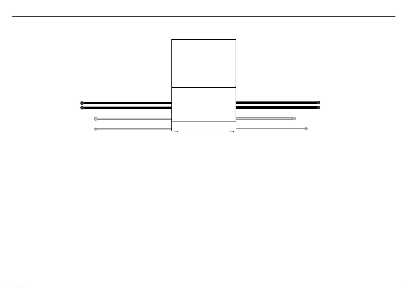
6 MAXIMUM DISTANCE OF HOSES & CORD FROM CHASSIS EDGE
LEFT HAND SIDE
Drain hoses—2000mm Drain hoses—1800mm
Inlet hose—1650mm Inlet hose—1250mm
Power cord (excl.plug)—1650mm Power cord (excl.plug)—1650mm
RIGHT HAND SIDE
6
NOW CHOOSE WHICH INSTALLATION METHOD (A) OR (B)
IS MORE SUITABLE FOR YOUR CABINETRY...
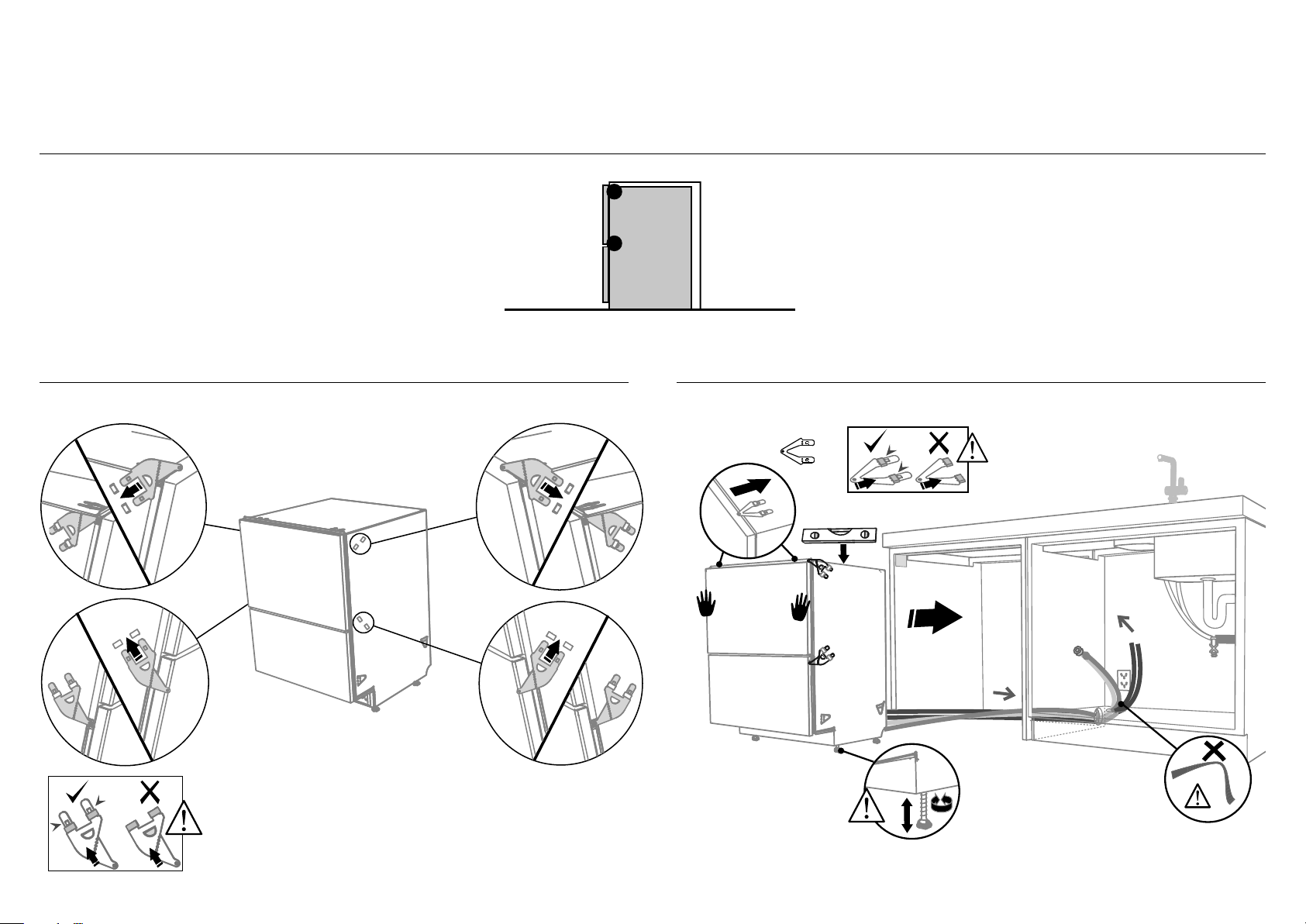
7 RECOMMENDED METHOD (A) — SECURE WITHOUT DRAWER REMOVAL (FRAMELESS CABINETRY ONLY)
8-A ATTACH SIDE MOUNTING BRACKETS 9-A PULL THROUGH HOSES & PUSH INTO THE CAVITY
Clip all four side mounting brackets
into their slots using a flat-bladed
screwdriver. Ensure they’re securely
fitted before sliding product into cavity.
AB
Optionally attach the
two top mounting
brackets
(x2)
Initially level the product
When fitting brackets,
ensure the ends are
not pushed down into
the chassis.
B
A
A
B
A
The mounting slots are in pairs, one on
each side diagonally across the product.
A bracket must match A slot and B
bracket must match B slot.
When fitting brackets, ensure the
ends are not pushed down into
the chassis.
7
B
You can raise or lower
the product by twisting
the feet. Then take
care when pushing the
product into the cavity
that you do not bend
the feet.
As you push product
in, pull through hoses
and cord, ensuring
they don’t get kinked
or twisted.
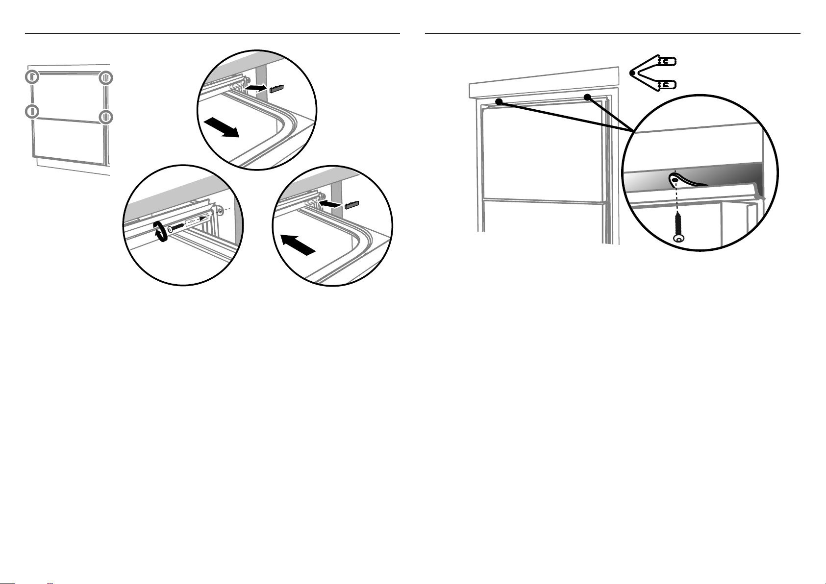
!0-A SECURE TO THE CABINETRY ON THE SIDES
!1-A OPTIONALLY SECURE TO THE CABINETRY ABOVE
Using a small Philips
screwdriver, screw
through the trim
moulding, securing the
side mounting bracket
to the cabinetry.
Do not damage the
rubber trimseal.
Open the drawer
halfway. Using
a flat bladed
screwdriver, prise
the grey rubber
plug out of the
trim moulding.
2
Repeat for all
four brackets.
1
Replace the grey
rubber plug back into
the trim moulding
and ensure the trim
seal is facing forward.
The top mounting
brackets will only
(x2)
bend upwards a
maximum of 10 mm.
3
!2-A AFTER SECURING, REFER TO ‘FIT THE SUPPLIED TOEKICK PANEL’ STEP
8
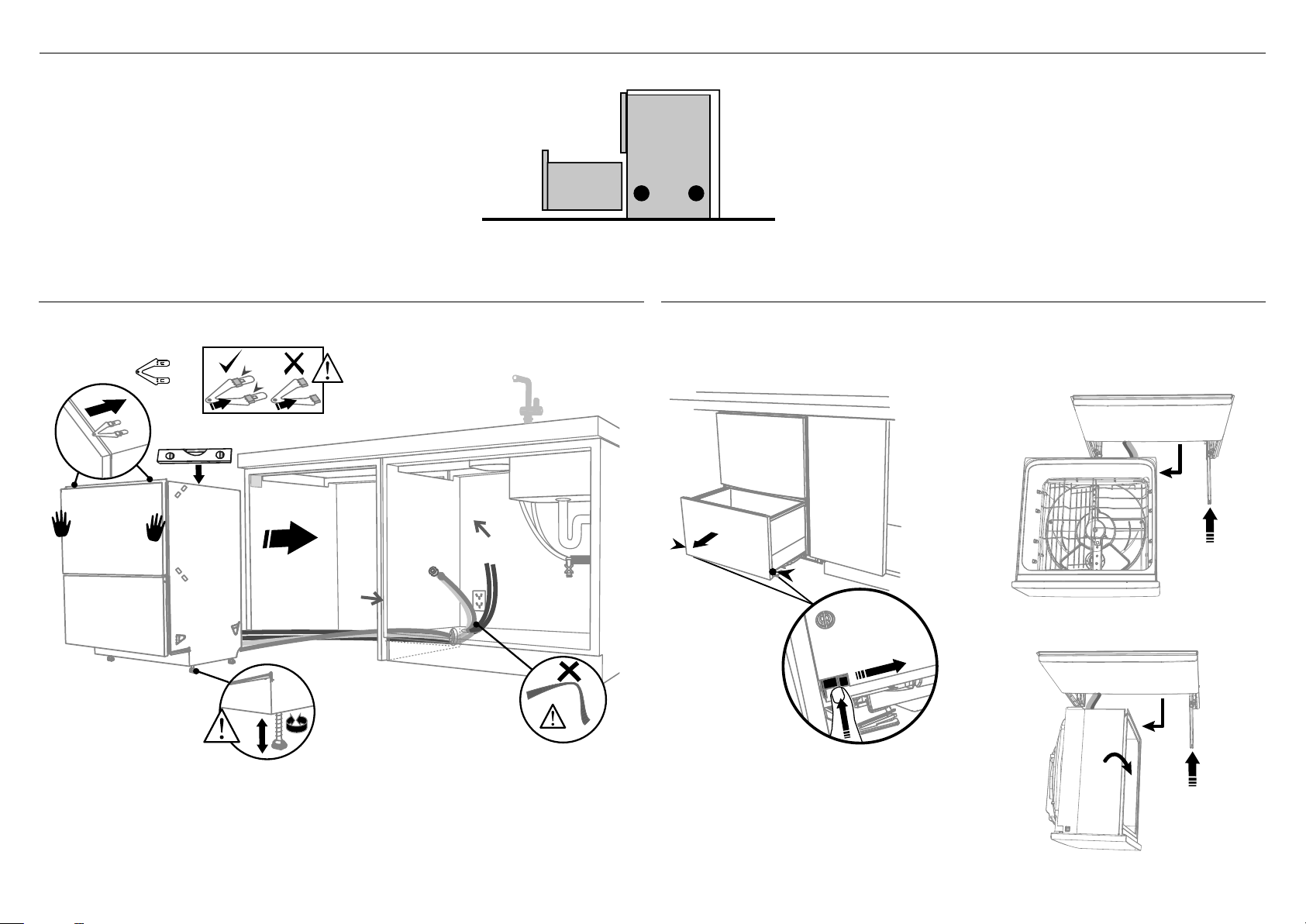
7 ALTERNATIVE METHOD (B) — SECURE BY DRAWER REMOVAL
8-B PULL THROUGH HOSES & PUSH INTO THE CAVITY 9-B REMOVE THE LOWER DRAWER
optionally attach the
two top mounting
brackets
(x2)
You can raise or
lower the product
by twisting the
feet. Then take care
when pushing the
product into the
cavity that you do
not bend the feet.
9
Initially level the product
When fitting brackets,
ensure the ends are
not pushed down into
the chassis.
As you push product
in, pull through hoses
and cord, ensuring
they don’t get kinked
or twisted.
1
2
100 mm
Press the release tabs
in on either side and
push back to release
drawer from runners.
Lift drawer off runners.
To prevent kinked hoses
Either sit the drawer down on the left hand
side (recommended) or rotate the drawer
clockwise, resting it on its side after removal.
3
4
Push drawer
runners back in
Sit the drawer down
on either side.
3
4
Push drawer
Rotate the drawer
clockwise (max. 90
and rest on side.
o
)
runners back in
on either side.
 Loading...