

Fisher & Paykel DishDrawer DS602I, DishDrawer DS602, DS602, DS602I Installation Instructions Manual
USA
DS602 (Prefinished)
Part No. 599066/D
DS602I (Integrated)
Models DS602 DS602I

Single DishDrawer
Table of Contents
Section 1 General Information
1.1 Preparation
1.2 Product Specifications & Cavity Dimensions
1.3 Options for Installing Multiple Products
1.4 Electrical, Plumbing & Drainage Information
1.5 Product Parts
1.6 Additional Product Parts for Integrated DishDrawer
Section 2 Fitting the DishDrawer
2.1 DishDrawer Mounting Hole Locations
2.2 Connecting the Services
2.3 Flexible Extrusion Attachment for 24 Cavity
Section 3 Inserting DishDrawer Into Cavity
Section 4 Information for Cabinet Maker for Integrated DishDrawer
4.1 Integrated Drawer Front Dimensions
Section 5 Integrated Drawer Front Installation
5.1 Changing the Integrated Badge Enclosure
5.2 Disassembling the Integrated Badge Assembly
5.3 Assembling the Integrated Badge
5.4 Fitting the Badge, Handle & Mounting Panel to the Drawer Front
5.5 Fitting the Drawer Front to the DishDrawer
Section 6 Final Fitting For Single DishDrawer
Section 7 Final Checks
7.1 Installation Wet Test
7.2 Troubleshooting
Page DS_01
Weight - Full 93lb (42kg) Prefinished
- Empty 62lb (28kg) Prefinished
Electrical 110-120VAC
3 pin socket outlet
Drying Residual Heat &
Fan Assisted
Water Connection Recommended Hot
140°F (60°C) Max.
Water Pressure Maximum 139 p.s.i. (960 kpa)
Minimum 4.3 p.s.i. (30 kpa)
GENERAL INFORMATION
SECTION 1
The DishDrawer MUST
be installed to allow for
future removal from the
enclosure if service is
required.
Before installing the
DishDrawer, remove the
house fuse or open the
circuit breaker.
Ensure all water
connections are turned
OFF.
WARNING
WARNING
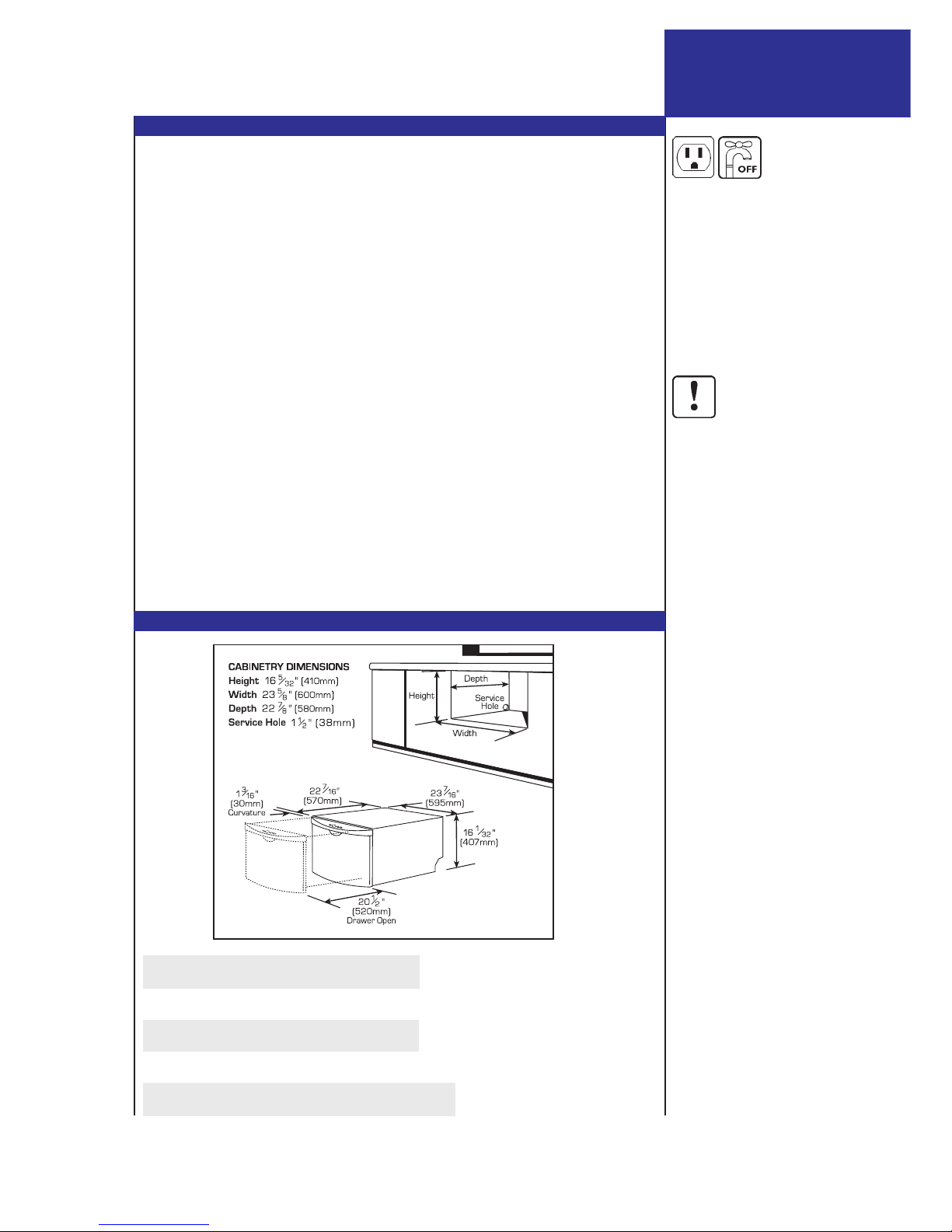
STEP 1.2 PRODUCT SPECIFICATIONS & CAVITY DIMENSIONS
STEP 1.1 PREPARATION
Page DS_02
NOTE TO THE INSTALLER
n Be sure to leave these instructions with the Customer.
n Ensure this appliance is properly grounded.
NOTE TO THE CONSUMER
n Keep these Installation Instructions with your Use & Care Manual for future
reference.
IMPORTANT
n Read these Instructions completely and carefully.
n Observe all governing Codes and Ordinances.
WARNING
n These Instructions are intended as a guide only.
n It is the responsibility of the plumber and electrician to ensure that each installation
complies with all Codes and Ordinances.
n Installation of this DishDrawer requires basic mechanical and electrical skills.
n The installer is responsible for the DishDrawer installation.
Improper installation is not covered under the Express Warranty Form.
IMPORTANT
n At the completion of the DishDrawer installation, the Installer must perform Final
Checks as per Section 7 of these Installation Instructions.
n Ensure the DishDrawer enclosure is prepared for installation.
n Remove all packaging and materials supplied with the DishDrawer.
n If you have any questions concerning the installation of this DishDrawer, contact:
Fisher & Paykel Customer Care Centre 27 Hubble
TOLL FREE 1-888-9-FNP USA Irvine
TOLL FREE 1-888-9-367 872 CA 92618
Fax (949) 829 8699 USA
WWW.FISHERPAYKEL.COM
(Water pressure below 7 p.s.i. (50 kpa)
may require the electronics to be
re-programmed by a Service Person
at the time of installation.)
Page DS_03
Where the DishDrawer is
in an under counter
situation, i.e. built into a
kitchen unit, it is
recommended that bare
wood surrounding the
DishDrawer is sealed with
an oil based paint or
polyurethane to prevent
possible steam damage.
IMPORTANT
IMPORTANT
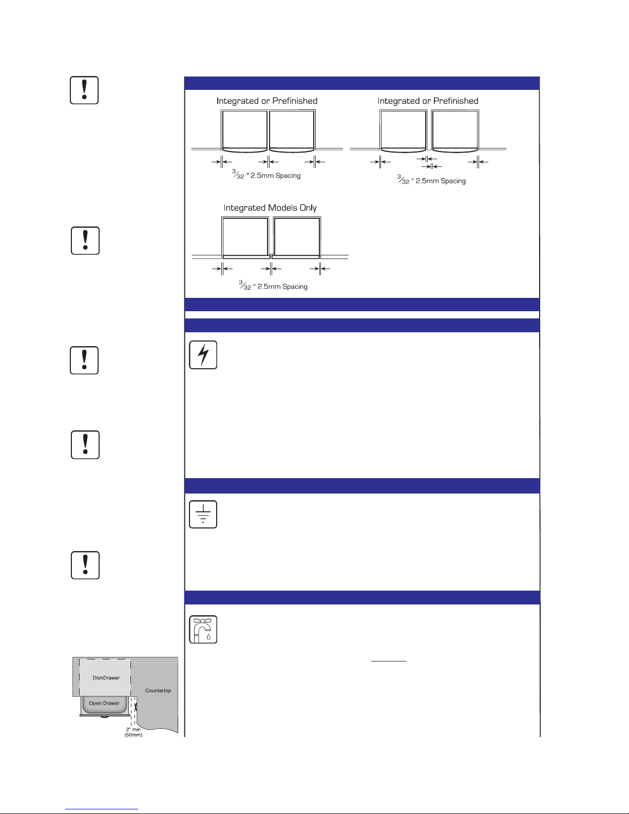
STEP 1.3 OPTIONS FOR INSTALLING MULTIPLE PRODUCTS
IMPORTANT
IMPORTANT
IMPORTANT
If mounting the
DishDrawer near the
bottom of the cabinet,
ensure there is adequate
room underneath the
supporting cabinet to
tighten bolts.
Ensure the cavity sides are
plumb (vertical) as this will
assist with leveling the
DishDrawer.
Ensure the Services Hole is
as close as possible to the
rear corner of the cabinet.
The hole can be located
on either side depending
on the location of the
services.
On corner installations
ensure that there is a gap
of 2" (50mm) minimum
between the adjacent
cabinetry and sides of
drawers.
STEP 1.4 ELECTRICAL, PLUMBING & DRAINAGE INFORMATION
ELECTRICAL
GROUNDING INSTRUCTIONS
PLUMBING - WATER SUPPLY
a) The water connection is to be made to a hot water supply only. Ensure the water
temperature is not greater than 140°F (60°C).
b) A readily accessible shut off valve must be installed in the supply pipe.
c) The water supply pressure is to be between 4.3 p.s.i. minimum and
139 p.s.i. maximum.
d) The inlet supply hose must be connected to the water supply using a 3/8"
compression type water supply fitting.
e) Ensure sealing washer supplied with connection hose is fitted.
This appliance must be grounded. In the event of malfunction or breakdown,
grounding will reduce the risk of electric shock by providing a path of least
resistance for electric current.
This appliance is equipped with a cord having an equipment-grounding conductor and a
grounding plug. The plug must be plugged into an appropriate outlet that is installed and
grounded in accordance with all local Codes & Ordinances.
Care should be exercised when the appliance is installed or removed, to
reduce the likelihood of damage to the power supply cord.
If the power supply cord is damaged, it must be replaced by the Manufacturer, its Service
Agent or a similarly qualified person, in order to avoid a hazard.
The power supply receptacle for the appliance should be installed in a cabinet or on a wall
adjacent to the under counter space in which the appliance is to be installed.
The power supply receptacle should be positioned between 6" and 18" (150mm and
450mm) from the cabinet opening of the DishDrawer.
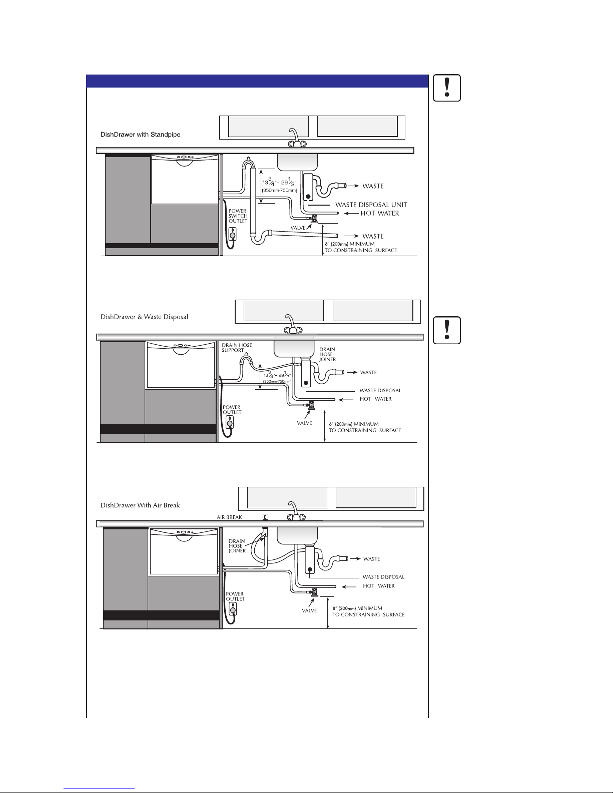
Note: DS602 Prefinished Model is shown. There is no variation in
plumbing between DS602 Prefinished Model and DS602I
Integrated Model.
Options 1 and 2 are the preferred options.
PLUMBING - DRAINAGE OPTIONS
Improper connection of
the equipment-grounding
conductor can result in a
risk of electric shock.
Check with a qualified
electrician or service
representative if you are
in doubt as to whether the
appliance is properly
grounded.
Do not modify the plug
provided with the
appliance - if it will not fit
the outlet, have a proper
outlet installed by a
qualified electrician.
The Drain Hose Support
must be at least 133/4"
(350mm) above the base
of the DishDrawer to
prevent siphoning of the
water during the wash
cycle.
It is recommended that
the Drain Hose Support is
secured in place using the
screw tab.
Ensure that the drain
hoses are fully extended.
WARNING
WARNING
Page DS_04
Option 1
Option 2
Option 3
Page DS_05
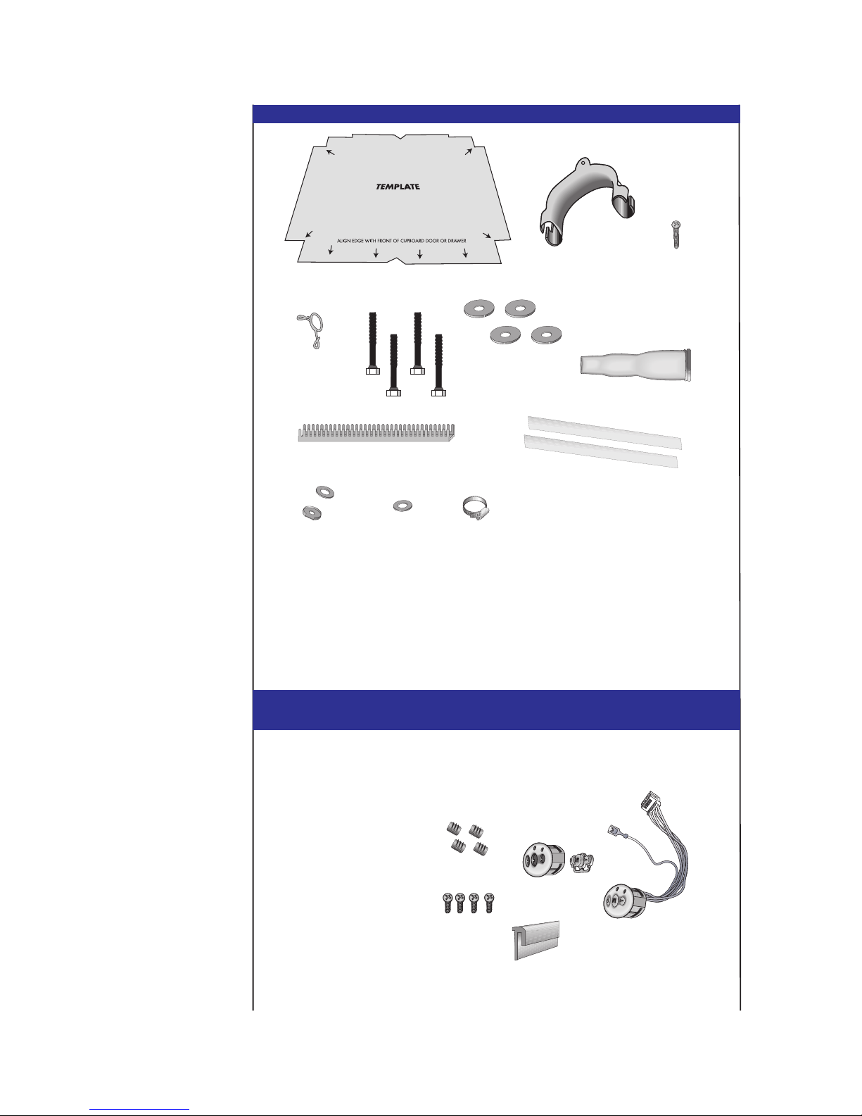
STEP 1.5 PRODUCT PARTS
Tools Needed To
Install DishDrawer
Wooden Chopping Board
Level
Safety Glasses
Utility Knife
Pencil
Drill & Drill Bits
(3/32", 9/16" & 11/32")
(2.5mm, 12mm, 14mm)
Sandpaper
Tape Measure
Square
Ruler
Phillips Screwdriver
Pliers
Adjustable Wrenches(x2)
7/32" (6mm) Allen Key
(Integrated Models)
Router (Integrated Models)
Jigsaw (Integrated Models)
STEP 1.6 ADDITIONAL PRODUCT PARTS FOR INTEGRATED
DISHDRAWER
1.
2.
3.
4.
5.
6.
7.
8.
9.
10.
11.
1. Template (Single 1)
2. Drain Hose Support (1)
3. Screw (1)
4. Wire Clip (1)
5. M8 Bolts (4)
6. Washers (4)
12.
7. Single Connector (1)
8. Edge Protector (1)
9. Flexible Extrusion 2)
10. Solderless Lug & Washer (1)
11. Inlet Hose Washer (1)
12. Hose Clamp (1)
13. Mounting Bracket Nuts (4)
14. Seal (1)
15. Door Screws (4)
16. Badge Kit (2)
13.
14.
15.
16.
 Loading...