

Fisher & Paykel DD60D Series Installation Instructions Manual
Important!
SAVE THESE INSTRUCTIONS
The models shown in this document may not be available in all markets and are subject to change at any time. For current details about model and specification availability in your country, please visit our
local website listed at the end of this document or contact your local Fisher & Paykel dealer.
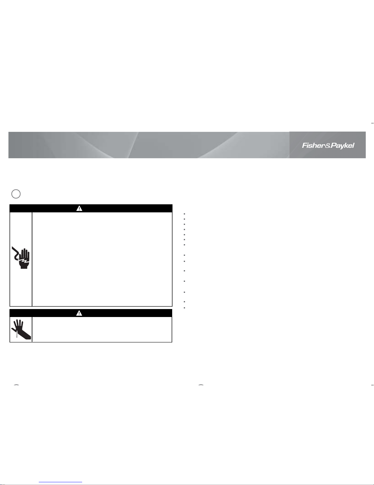
WARNING!
Electrical shock hazard
Before installing the DishDrawer®, remove the house fuse or open the circuit
breaker.
This appliance must be earthed. In the event of a malfunction or breakdown,
earthing will reduce the risk of electric shock by providing a path of least
resistance for electric current. This appliance is equipped with a cord having an
equipment-earthing conductor and an earthing plug. The plug must be plugged
into an appropriate outlet that is installed and earthed in accordance with all
local codes and ordinances. WARNING- Improper connection of the equipmentearthing conductor can result in a risk of electric shock. Check with a qualified
electrician or service representative if you are in doubt as to whether the
appliance is properly earthed.
Do not modify the power supply plug provided with the appliance - if it will not
fit the outlet, have a proper outlet installed by a qualified electrician. Do not use
an extension cord, adapter plug or multiple outlet box.
Failure to follow this advice may result in electrical shock or death.
WARNING!
Cut hazard
Take care - panel edges are sharp.
Failure to use caution could result in injury or cuts.
Important safety instructions!
Installation of this DishDrawer® requires basic mechanical and electrical skills.
Be sure to leave these Instructions with the Customer.
Installation must comply with your local building and electricity regulations.
At the completion of the DishDrawer® installation, the Installer must perform the Final Checklist.
Remove all packaging materials supplied with the DishDrawer®.
This DishDrawer® is manufactured for indoor use only.
Ensure all water connections are turned OFF. It is the responsibility of the plumber and
electrician to ensure that each installation complies with all Codes and Regulations.
The DishDrawer® MUST be installed to allow for future removal from the enclosure if service is required.
The switched power outlet must be outside the DishDrawer® cavity, so that it is accessible after
installation.
Care should be taken when the appliance is installed or removed to reduce the likelihood of damage to
the power supply cord.
If the DishDrawer® is to be relocated from one installation to another it must be kept upright to avoid
damage from water spillage.
Make sure only new hoses are used for connection (supplied with DishDrawer®). Old hoses should not
be reused.
Failure to install the DishDrawer® correctly could invalidate any warranty or liability claims.
If the product is installed in a motor vehicle, boat or similar mobile facility, you must bring the vehicle,
boat or mobile facility containing the product to the service shop at your expense or pay the service
technician’s travel to the location of the product.
DishDrawer®
Installation instructions
DD60D models
NZ AU GB IE SG
SAFETY AND WARNINGS
1
(1,1) -1- 599684C DD60D installA2 NZGB.indd 26/4/10 11:07:19 AM
(1,1) -1- 599684C DD60D installA2 NZGB.indd 26/4/10 11:07:19 AM
O
B
C
E
D
F
J
G
H
N
I
Installation diagrams for illustration purposes only
K
L
M
A
N
G
C
P
I
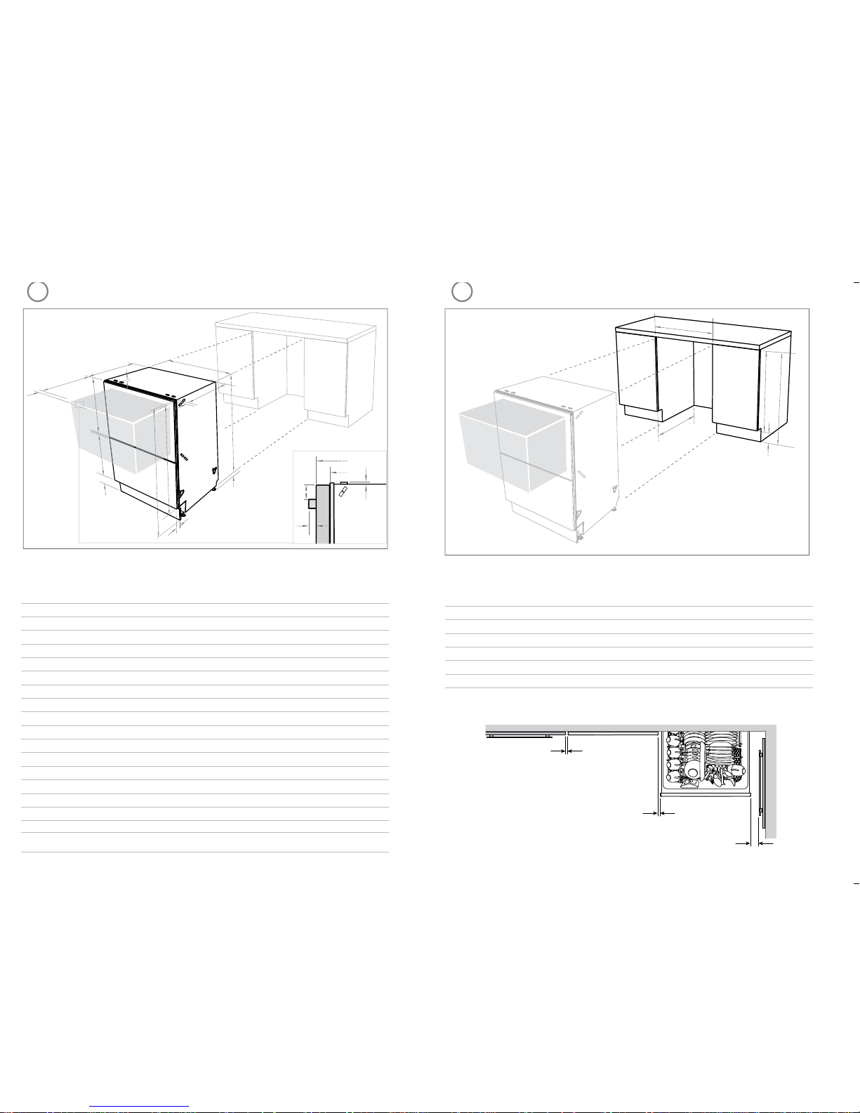
Product dimensions (mm)
Pre nished
LCD
DD60DC(H)X
DD60DC(H)B
DD60DC(H)W
DD60DCM
Pre nished
Flat door
DD60DDF(H)X
DD60DDFM
Integrated
DD60D(H)I
A
overall height* of product 819.5- 879.5 819.5- 879.5 819.5- 879.5
B
overall width of product 599 599 599
C
overall depth of product (excl. curvature/handle) 570 570 570
D
depth of drawer (open) (excl. curvature/handle) 538 538 538
E
height* of chassis 809 809 809
F
height range of levelling feet 60 60 60
G
depth of chassis (incl. trimseal) 552 552 552
H
depth of front panel (excl. curvature/handle) 18 18 18
I
depth of curvature or handle 11 41 n/a
J
depth of toekick 50 - 65 50 - 65 67 - 127**
K
height of upper panel front 394 398 398 min
L
height of lower panel front 312.5 311.5 311.5 min
M
height of toekick panel (adjustable) 70 - 120 70 - 120 70 - 120
N
height of installation bracket slots (on top of chassis) 22 2
O
height of drawer fronts 719.5 717.5 717.5 min
P
height from top of handle to top of front panel n/a 64 n/a
* Chassis heights include bracket slots
** Pre nished 50-65 mm; Integrated 67 mm less the Toekick Panel thickness (Minimum Panel thickness using the
supplied screws is 9 mm).
Cabinetry dimensions (mm)
Pre nished
LCD
DD60DC(H)X
DD60DC(H)B
DD60DC(H)W
DD60DCM
Pre nished
Flat door
DD60DDF(H)X
DD60DDFM
Integrated
DD60D(H)I
A
inside height of cavity 820- 882.5 820- 882.5 820- 882.5
B
inside width of cavity 600 600 600
C
inside depth of cavity (inside) 580 580 580
D
height of adjacent cabinetry 720 720 min. 720
E
height of toekick space 100 - 160 100 - 160 100 - 160
Minimum clearances (mm)
A
B
C
D
E
Installation diagrams for illustration purposes only
23
PRODUCT DIMENSIONS CABINETRY DIMENSIONS
2.5 mm
2.5 mm
13 mm
(1,2) -1- 599684C DD60D installA2 NZGB.indd 26/4/10 11:07:19 AM
(1,2) -1- 599684C DD60D installA2 NZGB.indd 26/4/10 11:07:19 AM
Clamp (1)
Wire clip (2)
Phillips
16 mm
screws (9)
Drain hose
support (1)
Moisture protection
tape (1)
(to prevent moisture
damage)
Drain hose
joiner (1)
Top
mounting
brackets (2)
OPTIONAL
Prefinished toekick (1)
white or black
Rubber
washer for
inlet hose (1)
Hexagonal
socket (2)
(long & short)
If the Drain hoses supplied are not long enough to reach your services, you must use a Drain Hose Extension Kit P/N 525798 which will extend the drain hoses by 3.6 m. The kit is available from the nearest
Fisher & Paykel Authorised Service Centre or our local website listed at the end of this document.
PARTS SUPPLIED
4
5
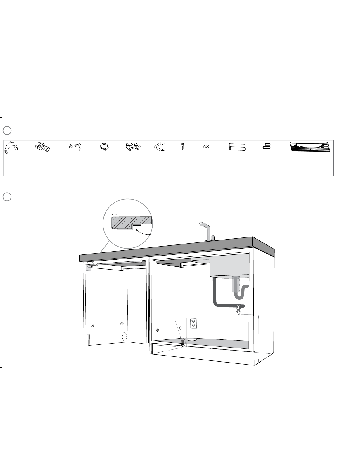
CAVITY PREPARATION
*
Note: Services can be located
either side of DishDrawer®.
220-240 VAC min. 9.5 A
min.
200 mm
10 mm
min. ø
60 mm
Moisture
protection
tape must
be applied.
*
Water supply
Waste disposal
(optional)
Side mounting
bracket kit
(A and B) (2)
OPTIONAL
(2,1) -1- 599684C DD60D installA2 NZGB.indd 26/4/10 11:07:19 AM
(2,1) -1- 599684C DD60D installA2 NZGB.indd 26/4/10 11:07:19 AM
 Loading...