

Fisher & Paykel AeroSmart Series, AeroSmart DG62T27C, AeroSmart DE62T27C Installation Instructions And User Manual
For your the
information in this manual must be
followed to mb_imize tSe risk of fire or
or to
damage, persor_al b_jury or death°
--Do not store or use gasolir_e or other
flammable vapors and liquids ire the
vici_ri+y of this or any other appliam;e°
--WHAT TO DO IF YOU SMELL GAS
+ Do not try to l[glht a++y appliance°
+ Do not touch any electrical switch; do
not use arty phone ire your building,
+ Clear tie room, building or area of all
+ Immediately call your gas supplier from
a _eighbor's pSo_eo Follow the gas
supplier's irrstruc+ionso
+ [f you canrro+ reach your' gas supplier',
call the fire departme_+t°
and service must be
performed by a qualified installer', service
agency or tie gas supplier,
Espa ol 64 = 119
The Governor of California is required to pub/sh a list of substances known to the
state of California to cause cancer or reproductive harm and requires business to
warn customers of potentiM exposures to such substances
Gas appliances contain or produce substances, which can cause death, or serious
illness and which are known to the State of California to cause cancer, birth defects,
or other reproductive harm To reduce the risk from substances in fuel or f_om
fuel combustion, make sure this appliance is instaHed, operated, and maintained
accord[n 9 to the manufacturers instructions
_ntroductio_
_mpod:ant sa[ety insl.ructions
_nstalladon instructions
The first time you turn yo_Jr'@'yet or_
Getdng starCed quk:kly
Operating ir_strud io_s
AeroSmart controls
EasyIouch controls, The display screels
S2
S4
S4
S6
S6
S7
Sorti_g and loading
Lint bucket
Choosing your @ying cycle
Changing the @ying cycle options
Drying cycle options
Dryir_g cycle progress
Dryir_g cycles expbsi_ed
S7
S8
S9
40
41
42
4S
46
Special Care Handwash /Jeans / Fresher_ Up / Warm Up / Dryd_ an
Com[oder / Pilk)ws / AII_ rgy / Shids //-owels / _ofi Toys
Spodswear Light _,p srtswu:ar Heavy / Outdoor Wear /
/_, f" .... s.....
47
48
50
Care IabeIs 51
Lid Lock 52
Power failure 52
Settings Menu 53
Alarm Level / Screen Brightness/Key Lock Mode 53
Reminders / Hinls / Language 54
Service Contacls / _rouble Shootilsg / []eset De%ults / [:/eplay hs_ro 55
Caring For your AeroSmart: dryer' 56
BeFore yo_JcalI lot service 57
I/your Ae_oSmart dryer beeps/or help 57
Solving operating problems 58
Solving drying problems 59
Limited warranty 60
2
S
7
SAVE THESE INSTRUCTIONS
The models shown in this user guide may not be available in aJ[ markets and are subject to
change at any time. For current details about model and specification availability in your country,
please go to our website www.fisherpaykeLcom or contact your local Fisher & Paykel dealer.
nt,roduction
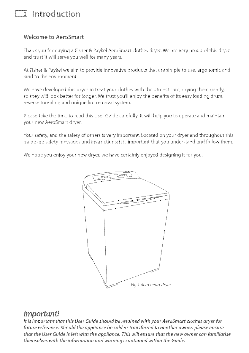
Welcome to AeroSma_t
Thank you for buying a Fisher & Paykd AeroSmart clothes dryer, We are very proud of this dryer
and trust it will serve you well for many years
At Fisher & Paykd we aim to provide innovative products that are simple to use, ergonomic and
kind to the environment,
We have developed this dryer to treat your clothes with the utmost care, drying them gently,
so they will look better for longer We trust you'll enjoy the benefits of its easy loading drum,
reverse tumbling and unique lint removal system,
Please take the time to read this User Guide carefully, It will help you to operate and maintain
your new AeroSmart dryer,
'four safety, and the safety of others is very important Located on your dryer and throughout this
guide are safety messages and instructions it is important that you understand and follow them,
We hope you enjoy your new dryer, we have certainly enjoyed designing it for you,
\
\
\
\
\
it is importam' that _'hisUser Guide should be retained with your AeroSmart clothes dryer for
future reference, Should the applionce be sold or transferred to another owner, please ensure
that the User Guide is left with the oppliance_ This t,WNensure that _'henew owner can familiarise
themselves with the information end warnings contained within the Guide.
Ilmpolrtant safety instructions El}
Symbols will be used in this Guide to highlight when extra care is required, Abide by these at all
times to ensure you and your family are not harmed while operating your dryer,
It is important to always act with caution and use common sense when operating your dryer,
Use only as instructed by the User Guide,
This isthe safety alert symbol.This symbol alerts you to hazardsthat can kill
Thesafety alert symbol andthe word DANGERor WARNINGwill precede all
safety messages.Thesewords mean:
You can be killed or seriously injured if you don't
immediately, follow instructions°
You can be killed or seriously injured if you don't
follow instructions.
All safety messageswill identify the hazard,tell you how to reducethe chance of iniury,
andtell you what can happen ifthe instructions are not followed,
mportant safety inst/ uctions
Follow the safety precautions outlined in this User Guide°
Failure to do so can resutt in death or electric shock.
Read all instructions carefully before using this dty'er,
Use this dty'er on!y for its intended purpose as described in this User Guide.
To minimize the possibility of electric shock, unplug this dryer from the power supply or disconnect
the dryer at the household distribution panel (by removing the fuse or switching
off the circuit breaker') before attempting any user maintenance or cleaning.
Installations must be performed by a qualih_d or licensed contractor, plumber or gasfitter quafified
or licensed by the state, province, or region where this appliance is being installed.
This @yer must be proper!y installed and located in accordance with the Installation Instructions
before it is used.
T,_isdryer must be proper/}/grounded to conform with dill governing codes and ordinances. Follow
details in Installation Instructions.
Do not instal/ or store the do,,er where it wi/l be exposed to water or exposed to the weather.
Connect to apropedy protected, rated and sized power supply circuit to avoid electrical overload,
Do not repair or replace any part of the appliance or attempt any servicin b unless specifically
recommended in the published user repair instructions thot you understand and have the skills to
carry out,
When disconnecting the dt}¢er,puff by the plug rather than the cord orjunction of the cord plub to
avoid damage to the cord or junction of the cord plug.
Make sure the cord is located so that it will not be stepped on, tripped over or otherwise subject to
stress or damage.
Do not tamper with the controls or the lid lock.
Note: Pressing the POWER button doe_sNOT disconnect the dryer from the power supp!y, ew*n
though the lights are out.
Do not operate this dryer if it is damaged, malfunctioning, partial!y disassembled or has missing or
broken parts, including a damaged cord or plug,
T,_isdryer must be directly connected to an approved fixed electrical outlet. It cannot beplugged into
an extension cord.
mpo,rt ant safety in st,ructio ns
Fire Ha£a_d
Only dry fabrics that have been washed with water°
Do not use heat to dry articles containin 9 foam rubber or similarly textured
rubber-like materials,, Dry on the Air Dry cyc[eo
A clothes dryer produces combustible lint and must be exhausted
outdoors, Take care to prevent the accumulation of lint around the exhaust
openin 9 and in the surrour'_din 9 area°
Do not use fabric softeners or products to e_iminate £atic unmess
recommended by the manufacturer of the _abric softener* or product,,
Failure to follow these instructions can result in death or personat injury,
To reduce the risk of fire in a tumble dryer the following should be observed:
Do not place items in a tumble dryer that have previously been cleaned in, washed in, soaked
in, or spot cleaned with flammable liquids or solids They are a fire or explosion hazard
Highly flammable substances commonly used in domestic environments include acetone,
denatured alcohol, gasoline, kerosene, some brands of spot removers and dry cleaning solvents,
turpentine, waxes, wax removers, vegetable oil, fish oil, massage oil, and cooking oil
Do not leave hot oil-affected items in a pile or stack. This can prevent heat from escaping and
can create a fire hazard. Oil--affected items can ignite spontaneously, especially when exposed
to heat sources such as a tumble dryer. The items become warm causing an oxidation reaction
in the oil. This oxidation creates heat. If the heat cannot escape the items can become hot
enough to catch fire.
Do not use heat to dry terns containing rubber, foam rubber, plastic or similar materials, (such
as padded bras, bath mats, rugs, bibs, baby pants, plastic bags, pillows etc), as these materiaB
might melt or burn. Some rubber materials when heated can under certain circumstances
produce fire by spontaneous combustion. Dry only on the AIR DRY cycle.
Unless specifically recommended by their manufacturer, do not use fabric softeners or similar
products in a tumble dryer
Do not store or use gasoline or other flammable gases and liquids near this or any other
appliance.
Keep the area around and underneath your dryer free from the accumulation of combustible
materials such as lint, paper, rags, chemicals etc.
Do not store any items that may burn or melt (such as paper materials, plastics or plastic
containers etc) next to the dryer
Empty the lint bucket before the lint reaches the top of the transparent section (usually once a
week).
The dryer must be exhausted to the outside, Carefu{[y follow the venting details in the
Installation instructions.
Keep the floor around your dryer clean and dr},, to reduce the possibility of slipping
If }/our dryer is running and you want to unload or add clothes press START/PAUSE and wait
until the machine has unlocked the lid. Do not force it open.
mpo/rta IIr" tsafety illrsstlructions
Do not reach into the appliance if the drum is moving
Close supervision is necessary if this dryer s used by or near children, Do not alEow children to
play inside, around or with this dryer or any other appliance,
Never climb on, climb into, or stand on the dryer top, Eidor drum
Undergarments that contain metal reinforcements should not be placed directly in the dryer,
Damage to the dryer can result if the metal reinforcements come Eooseduring drying
The interior of the appliance and exhaust duct should be cleaned periodically by qualified
service personnel
Before the appliance is removed from service or discarded remove the lid and the drum door to
SAVE THESEINSTRUCTIONS
iiiii_i_iiii_@_@_@_@_@_@_@_@_@_@_@_@_@_@_i_iiiiiii_i_¸il¸lii¸ili¸iiiiiiiiiiiil,iiiii_!_!_iiiiiiiiiiiiii_iiiliiiliiiiiiiiiiiiiiiiiiiiil_i_i_iii_i_ii_iiii_iiii_iiiii_iiiii_iiiii_iiiii_iiiii_iiiii_iiiii_iiiii_iiiii_ii_i_i_i_i_i_i_ii_i_i_ii_i_i_ii_i_ii_iiii_iiii_iiiii_ii_iiii_iiiiiii_!iii_i_i_iiiiiii¸il¸ii'iiiiiiiii¸I¸I¸I¸il_il_ii_il_ii_il_I_iiiiiiiiiiiil¸ii:i'ii'iiiiill
_nstalllllationinst,ructions _iI
Read the important safety instructions on pages 3 - 6 before you start installing the dryer.
Checktomakesureyouhaveallthetoolsandpartsnecessarytocorrectly_nstallth_sappUance,
Tools required
Y4"nut driver or socket wrench
Phillips screwdriver
Fiat-blade screwdriver
Adjustable wrench B" or 10" (200 mm or 250 ram) for gas connections
Pipe joint compound (pipe dope or tape) for gas pipe connections that is resistant to
LP Propane, Butane and Natural Gas (Gas models only)
Level
Caulking gun and compound (for nstaJling new exhaust vent)
Gloves
Knife
Duct tape
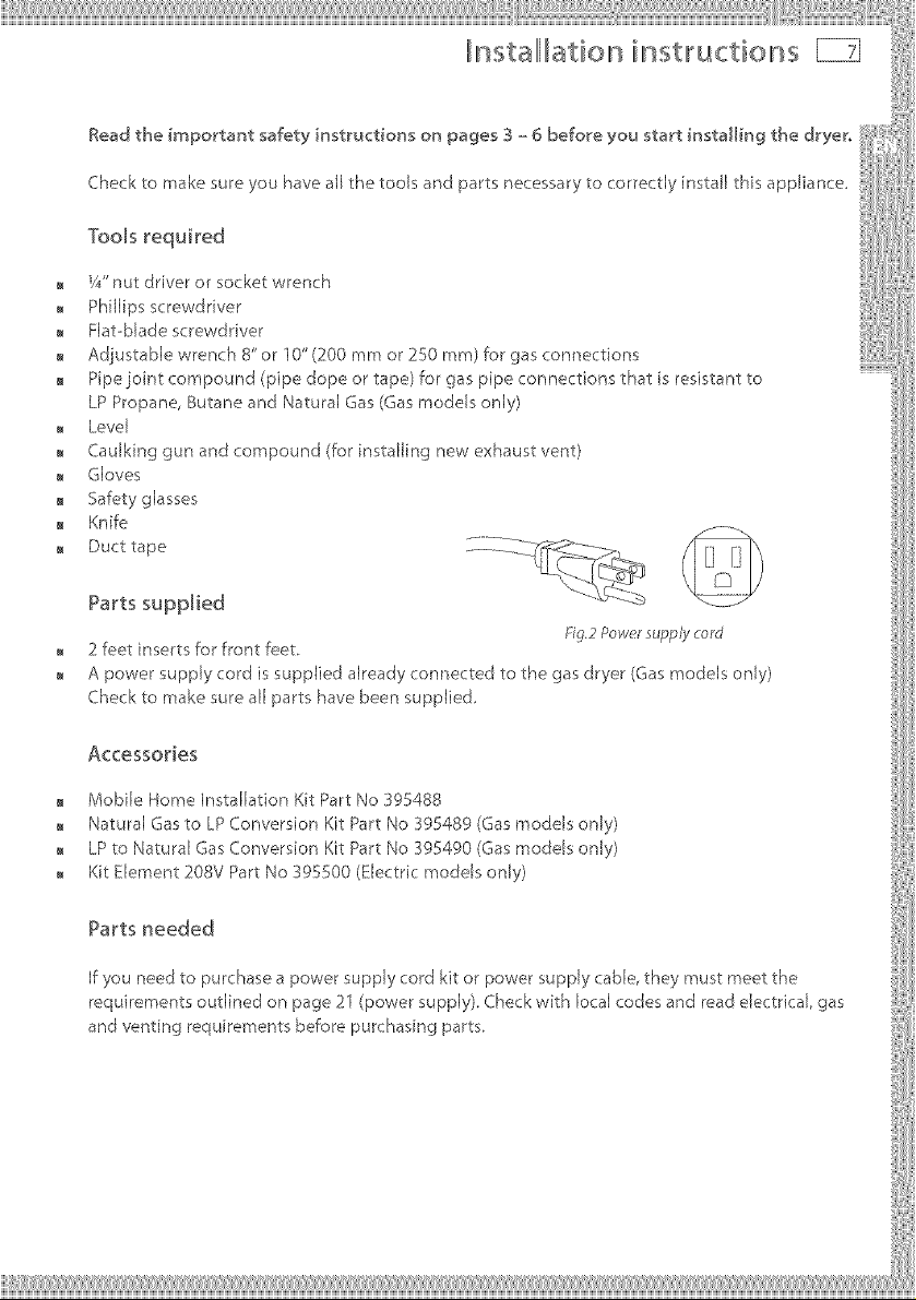
Parts supplied
2feet inserts for front feet
A power supply cord issupplied already connected to the gasdryer (Gasmodels only)
Checkto make sure all parts have been supplied,
1i_.2powersupplycord
Accessories
Mobile Home Installation Kit Part No 395488
Natural Gas to LP Conversion Kit Part No 395489 (Gas models only)
LP to Natural Gas Conversion Kit Part No _95490 (Gas models only)
Kit Element 208V Part No 395500 (Electric models only)
Parts needed
If you need to purchase a power supply cord kit or power supply cable, they must meet the
requirements outlined on page 21 (power supply). Check with local codes and read dectricaJ, gas
and venting requirements before purchasing parts,
llL stallllllati© illL structior s
To the installer
The correct installation of the dryer is your responsibility.
Be sure you read the following instructions carefully before you start to install the dryer. These
instructions should be left with the home owner for future reference.
It is your respor_sibHity to:
Observe all governing codes and ordinances.
Check code requirements. Some codes limit or do not permit installation of clothes dryers in
garages, closets, mobile homes or sleeping quarters. Contact your local building inspector.
Adhere to these nstallation nstructions.
Allow for spacing requirements with side by side installations (refer page g).
Make sure you have all items necessary for correct installation.
Properly install the dryer.
Contact a qualified installer to ensure that the electrical and gas installation meets all national
and local codes and ordinances (See page 4),
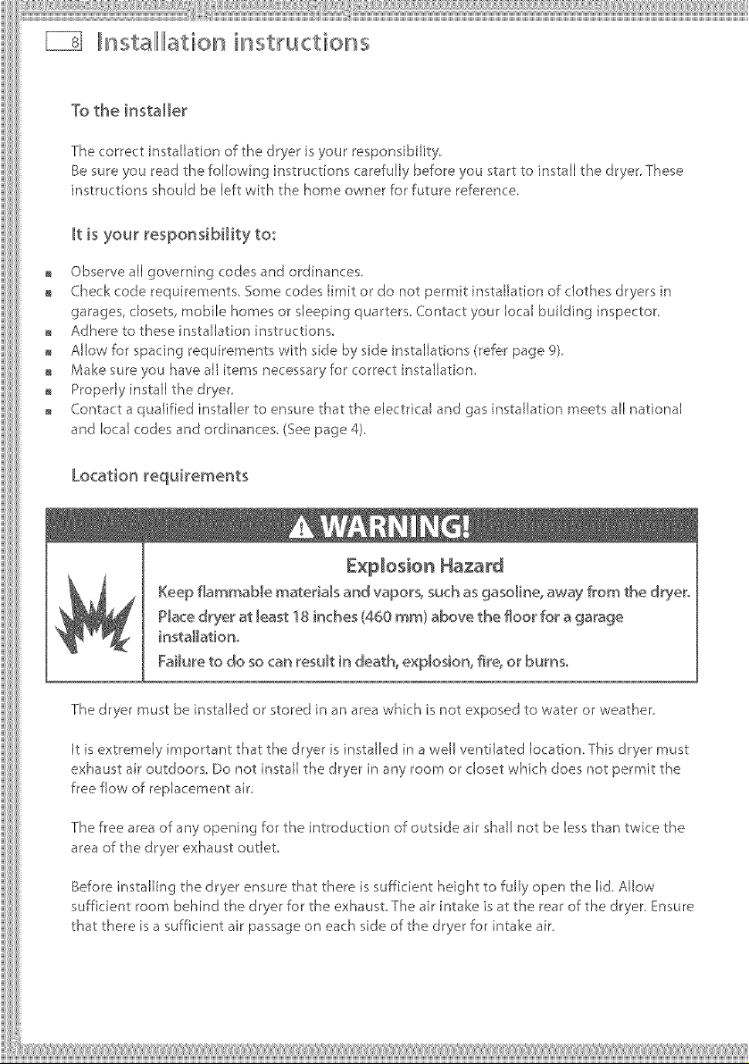
Location requirements
Explosion Hazard
Keep f[ammaMe materials and vapor& such as gasoline, away from the dryer.
P_ace dryer at _east 18 inches (460 ram) above the floor for a garage
instaHationo
Failure to do so can result in death, explosion, fire. or burns.
The dryer must be installed or stored in an area which is not exposed to water or weather.
It is extremely irnportant that the dryer is installed in a well ventilated location, This dryer must
exhaust air outdoors, Do not install the dryer in any room or closet which does not permit the
free flow of replacement air,
The free area of any opening for the introduction of outside air shall not be less than twice the
area of the dryer exhaust outlet.
Before installing the dryer ensure that there is sufficient height to fully open the lid. Allow
sufficient room behind the dryer for the exhaust. The air intake is at the rear of the dryer. Ensure
that there is a sufficient air passage on each side of the dryer for intake air.
IlllnstaIIIIlationinstructions
Location requirements
The area in which the dryer is located must be
kept clear and free from combustible materials,
gasoJine and other flammabJe vapors and
liquids. A dryer produces combustibJe [int so the
area around the dryer must be cleaned reguJarJy
to keep it free of lint. Fig.3Rearw*nting
This dryer can only be vented from the rear and must be exhausted to the outdoors.
Alcove or closet installation
When installing a dryer in a cbsedalcove it must be exhausted _o the outdoors. No other
fuel burning appliance can be installed in the same closet or a[coveo
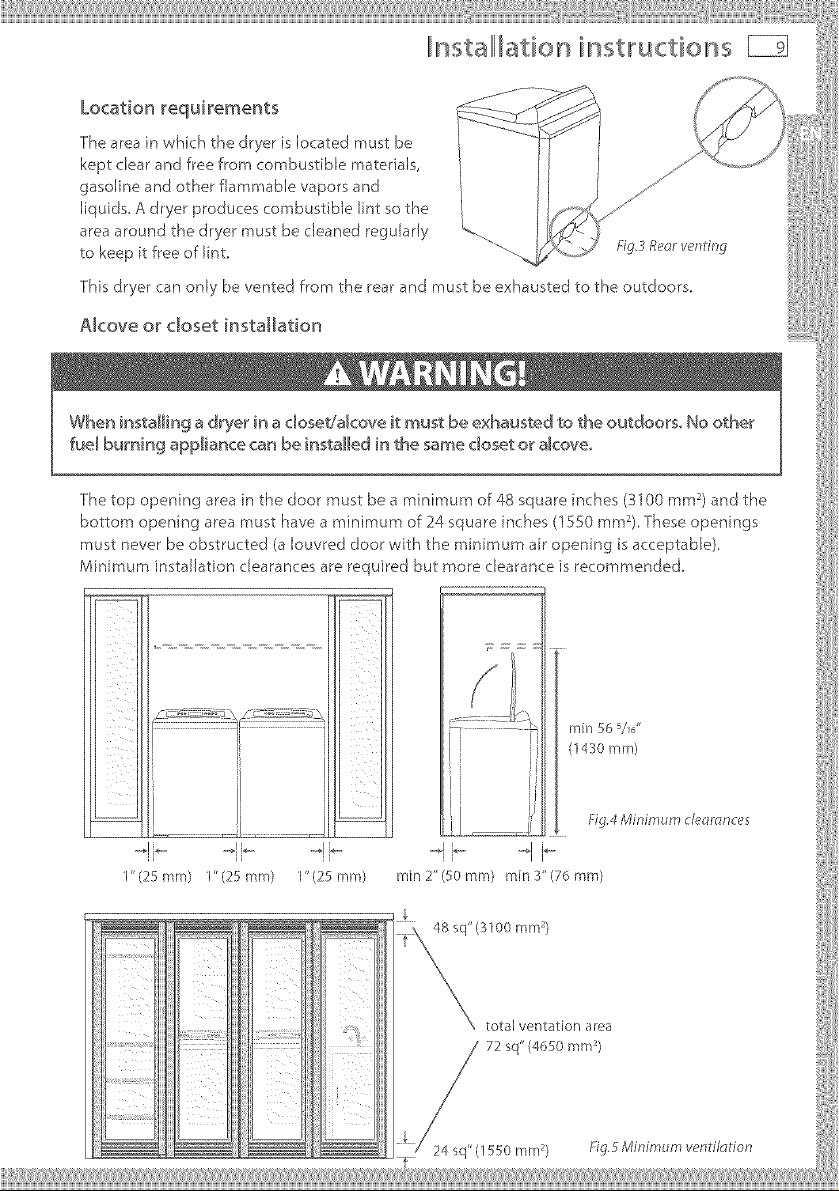
The top opening area in the door must be a minimum of 48 square inches (31 O0 mm 2)and the
bottom opening area must have a minimum of 24 square inches (1550 mm 2) These openings
must never be obstructed (a [ouvred door with the minimum air opening is acceptable).
Minimum installation cJearances are required but more cJearance is recommended.
L
ii ii
1" (25 mm) 1"(25 mm) I" (25 mm)
rain 565/6"
(1430 mm)
.._1b....... .I i_m
[ J II
rain 2" (50 ram) rain 3" (76 ram)
fig.4 Minimum deomnces
_] _,L_stalllllati©,L_h_st,ructions
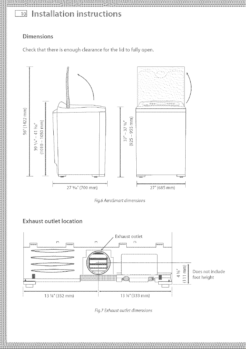
Dimensions
Checkthat there is enough clearance for the lid to fully open.
S
27'!JJ'(700 mm)
Exhaust outlet Jocation
137a" (352 mm} 13 W' (333 mm)
,2
[
L
27" (685 ram)
1:i9.6 Aero_.mor_ dimensions
Fig.7 Exhd_ sl o_d_t dir'nen io_s
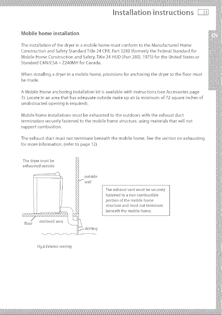
Mobile home i_stallation
The installation of the dryer in a mobile home must conform to the Manufactured Home
Construction and Safety Standard Title 24 CFR, Part 3280 {formerly the Federal Standard for
Mobile Home Construction and Safety, Title 24 HUD (Part 280), 1978} for the United States or
Standard CAN/CSA - Z240MH for Canada,
When installing a dryer in a mobile home, provisions for anchoring the dryer to the floor must
be made,
A Mobile Home anchoring installation kt is available with instructions (see Accessories page
7), Locate in an area that has adequate outside make up air (a minimum of 72 square inches of
unobstructed opening is required),
Mobile home installations must be exhausted to the outdoors with the exhaust duct
termination securely fastened to the mobile home structure, using materials that will not
support combustion,
The exhaust duct must not terminate beneath the mobile home, See the section on exhausting
for more information, (refer to page 12)
The dryer must be
exhausled outside
outside
*_wall
The exhaust vent must be securely
fastened to a noncombustible
portion of the mobile home
stR/( _ure and must not terminate
beneath the mobile home.
floor enclosed area
i
,qg.8Yxlerior vending
¸il¸liiii¸il¸liiiii¸I¸II¸iiiil¸ii i i iiiil¸il¸ii'i iiiiiii¸il¸iiiii:ii¸iliiii'liiii¸I¸ii'iii iiii¸I¸ii iiiiiiil
lnstalllllation ilnstlructions
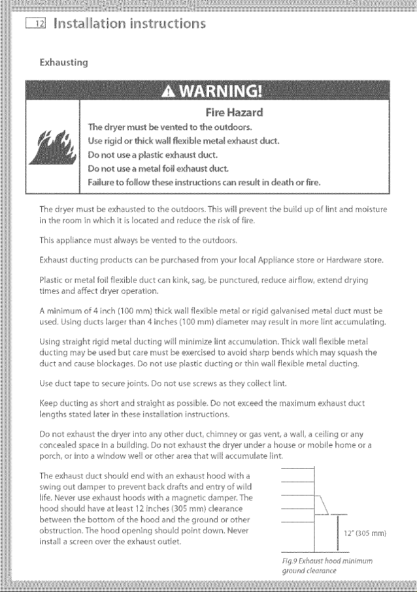
The dryer must be ve_ed to the outdoo_s_
Ose rigid or thick wall fle×iMe metal exhaust duct,
Oo _ot use a p_astic exhaust duct,
Do not use a meta_ foi_ exhaust duct.
Failure to follow these instructions can result in death or fire.
The dryer must be exhausted to the outdoors. This will prevent the build up of lint and moisture
in the room in which it is located and reduce the risk of fire.
This appliance must always be vented to the outdoors.
Exhaust ducting products can be purchased from your local Appliance store or Hardware store.
Plastic or metal foil flexible duct can kink, sag, be punctured, reduce airflow, extend drying
times and affect dryer operation.
A minimum of 4 inch (100 ram) thick wall flexible metal or rigid galvanised metal duct must be
used. Using ducts larger than 4 inches (100 mm) diameter may result in more lint accumulating.
Using straight rigid metal ducting will minimize lint accumulation. Thick wall flexible metal
ducting may be used but care must be exercised to avoid sharp bends which may squash the
duct and cause blockages. Do not use plastic ducting or thin wall flexible metal ducting
Use duct tape to secure joints. Do not use screws as they collect lint.
Keep ducting as short and straight as possible. Do not exceed the maximum exhaust duct
lengths stated later in these nstalJation nstructions.
Do not exhaust the dryer into any other duct, chimney or gas vent, a wall, a ceiling or any
concealed space in a building Do not exhaust the dryer under a house or mobile home or a
porch, or into a window well or other area that will accumulate lint.
The exhaust duct should end with an exhaust hood with a
swing out damper to prevent back drafts and entry of wild
life. Never use exhaust hoods with a magnetic damper The
hood should have at least 12 inches (305 mm) clearance
between the bottom of the hood and the ground or other
obstruction The hood opening should point down. Never
install a screen over the exhaust outlet.
_ig.9Yxh_usthood minimum
ground deoro,nce
,,,,,,,,,,,,,,,,,,,,,,i)
Toreducecondensation,insulateanyductingwhichpassesthroughunheatedareas.Slopethe
ductgentlydownwardstothehood,todraincondensationandreducelintbuildup,Avoidsag
orloopsintheductastheymaycollectandstorewaterandaccumulatelint.
Beforeusinganexistingexhaustductsystemforadryerensurethat:
NopEasticorotherpotentiallycombustibEeductorflexiblemetalfoilductinghasbeenused.
Theductisnotpierced,kinkedorcrushed.
Theductdoesnotexceed the maximum recommended length for the new dryer.
The exhaust hood damper opens and closes freely and with sufficient movement.
Static pressure in the exhaust ducting does not exceed 1 inch (250Pa), or s not less than 0
inches of water column fie. negative pressure), when measured with a manometer in the first 6
inches of the duct, wth the dryer running on Air Dry (no heat) setting.
The exhaust duct system meets aJ[ relevant local, state and national codes.
All ducting should be inspected and cleaned at least once a year to remove accumulated lint.
Frequently check that the damper on the exhaust hood moves sufficiently and opens and
Mobile Home Installations
A Mobile Home Installation Kit is available (see Accessor es page 7).
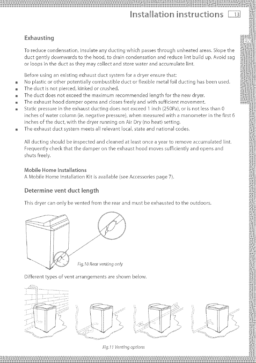
Determine vent duct length
This dryer can only be vented from the rearand must be exhausted to the outdoors,
...._ Fig.70Reclrvenling only
Different types of vent arrangements are shown below.
i
fig. 11V_'ndngoptions
nstallllation instlructions
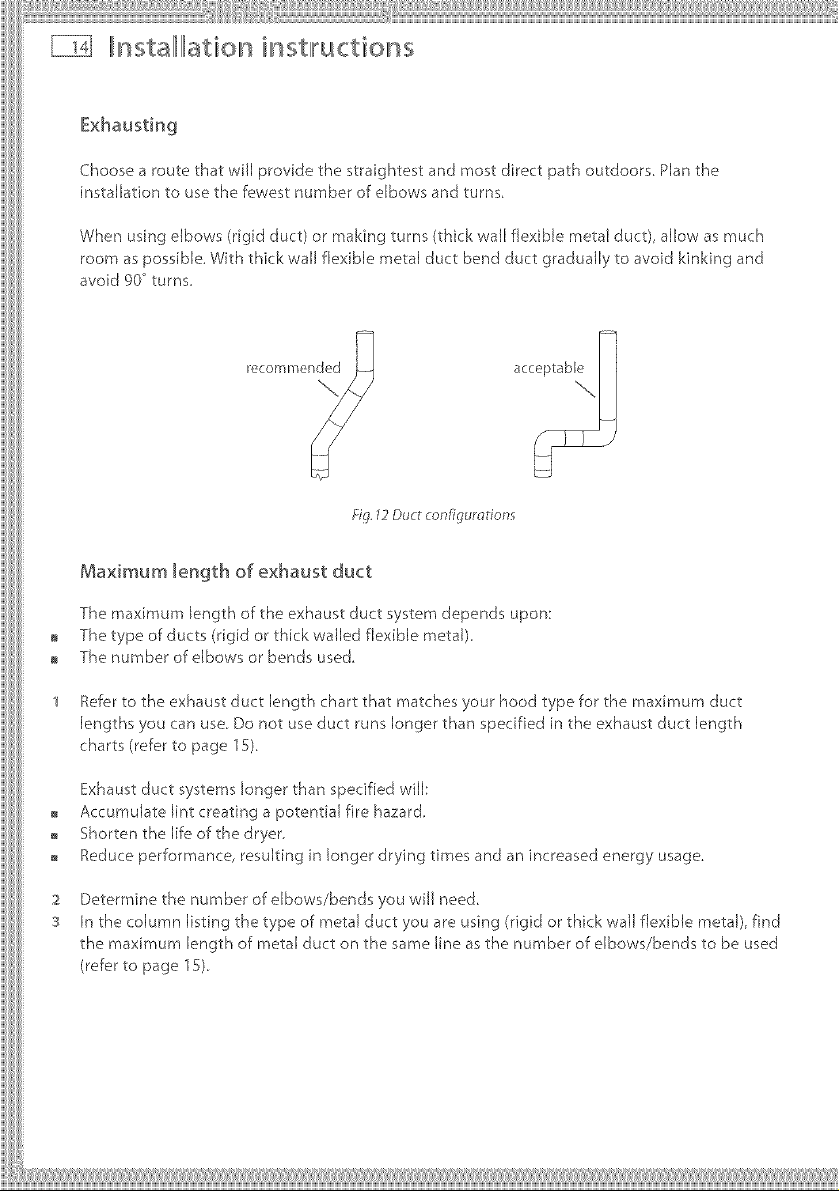
Choose a route that will provide the straightest and most direct path outdoors, Plan the
installation to use the fe__westnumber of elbows and turns,
When using elbows (rigid duct) or making turns (thick wall flexible metal duct), allow as much
room as possible, With thick wall flexible metal duct bend duct gradually to avoid kinking and
avoid 90 °turns,
Fig.12Dud configumfion_
Maximum length of exhaust duct
The maximum length of the exhaust duct system depends upon:
The type of ducts (rigid or thick walled flexible metal),
The number of elbows or bends used
Refer to the exhaust duct length chart that matches your hood type for the maximum duct
lengths you can use. Do not use duct runs longer than specified in the exhaust duct length
charts (refer to page 1S),
Exhaust duct systems longer than specified will:
Accumulate lint creating a potential fire hazard,
Shorten the life of the dryer.
Reduce performance, resulting n longer drying times and an increased energy usage,
Determine the number of elbows/bends you wiJJ need
In the column listing the type of metal duct you are using (rigid or thick wail flexible metal), find
the maximum length of metal duct on the same line as the number of elbows/bends to be used
(refer to page 1S).
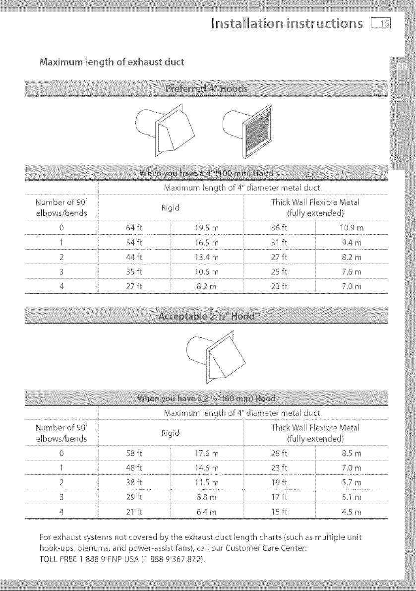
Maximum length of exhaust duct
Maximum length of 4" diameter metal duct.
Number of 900 Thick Wall Flexible Metal
elbows/bends Rigid
0 64 ft 195 rn 36 ft 10,9 m
1 54 ft 165 m 31 ft 9.4 m
2 44 ft 13.4 m 27 ft 8.2 m
3 35 ft 106 m 25 ft 7.6 rn
4 27 ft 8.2 m 23 ft 7.0 m
Maximum length of 4" diameter metal duct.
Number of 900 Thick Wall Flexible Metal
elbows/bends Rigid
0 58ft 176 m 28ft 8.5 m
1 48 ft 14.6 m 23 ft 7.0 m
2 38ft 115m 19ft 5.7m
3 29 ft 8.8 m 17 ft 5.1 m
4 21 ft 6.4m 15ft 4.5 m
For exhaust systems not covered by the exhaust duct length charts (such as multiple unit
hook-ups, plenums, and power assist fans), call our Customer Care Center
TOLL FREE 1 888 g FNP USA (1 888 g 367 872).
nstallilation instlructioss
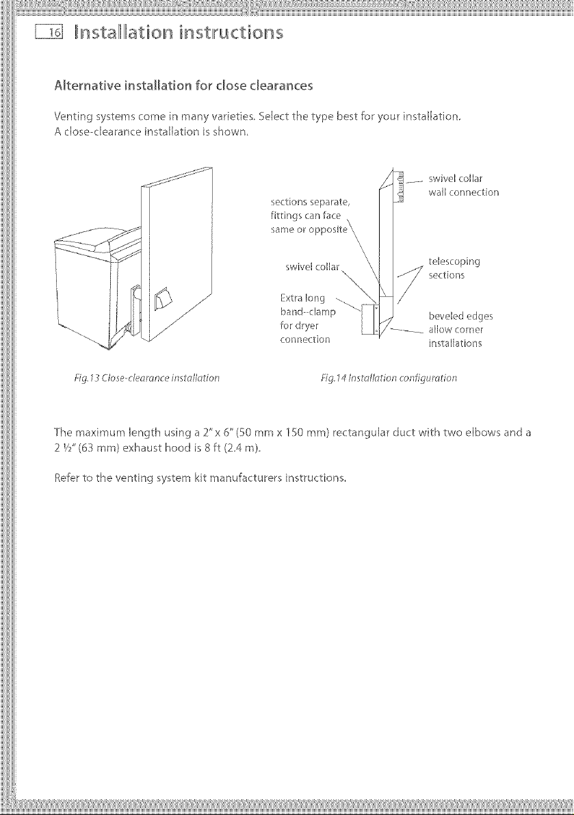
Alternative installation for close dearances
Venting systems come in many varieties. Select the type best for your instaNation,
A dose--clearance instalhtion is shown.
SSS_ _S_
sections separate,
(onnection
Fig. 73 C/ose c/eomnce insto//olion Fig. 14/nstd_//odon configumdon
il ...... swivel collarwall connection
telescoping
s(sctions
beveled edges
.......... allow corner
installations
The maximum length using a 2"x 6"(50 mmx 150 mm) rectangular duct with two elbows and a
2 V/'(6_ ram) exhaust hood is 8 ft (24 m),
Refer to the venting system kit manufacturers insWuctions,
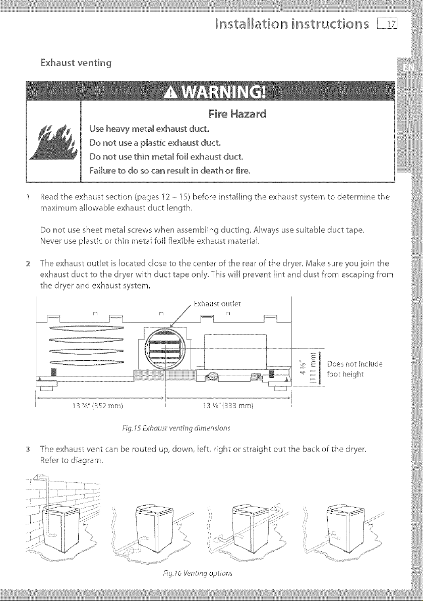
_,L_sta/111atio n i,L_st,ructio ns _z]
Fire Haza_'d
Use heavy meta_ exhaust duct,,
Do not use a p_astk exhaust duct.
Do not use thin metam foi_ exhaust duct
Failure to do so can resutt in death or _eo
Read the exhaust section (pages 12 - 15) before installing the exhaust system to determine the
maximum allowable exhaust duct length,
Do not use sheet metal screws when assembling ducting. Always use suitable duct tape,
Never use plastic or thin metal foil flexible exhaust material
The exhaust outlet is located close to the center of the rear of the dryer, Make sure you join the
exhaust duct to the dryer with duct tape only, This will prevent lint and dust from escaping from
the dryer and exhaust system,
13%" (352 ram) 13 f/8"(333 mm)
Fig. 75 Fxhdusl venting dimendons
The exhaust vent can be routed up, down, left, rght or straight out the back of the dryer,
Refer to diagram
\\
//
Fig, 76 Vendng options
lnsta llation instllructior' s
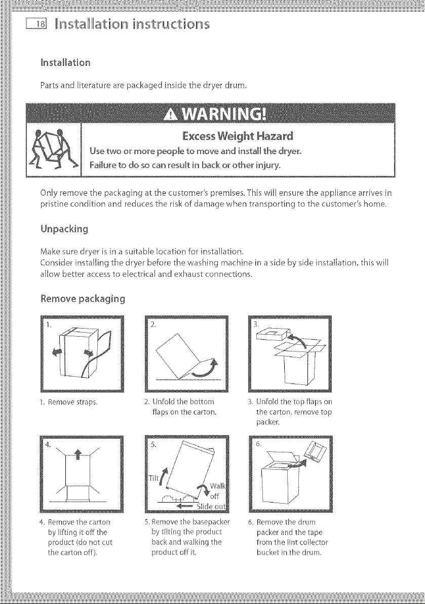
Installation
Partsand literature are packaged inside the dryer drum,
Only remove the packaging at the customer's premises This will ensure the appliance arrives in
pristine condition and reduces the risk of damage when transporting to the customer's home.
Make sure dryer is in a suitabEe location for installation.
Consider installing the dryer before the washing machine in a side by side installation, this will
allow better access to electrical and exhaust connections.
1.
1. Remove straps.
4
4 Remove the carton
by lifting it off the
product (do not cut
the carton off).
2,
2. Unfold the botlom
flaps on the carton.
Slide
S,Remove the basepacker
by tilting the product
back and walking the
product off it.
S.Unfold the top flaps on
the carton, remove top
packer.
6.
d. Removethe drum
packer and the tape
from the lint collector
bu ket in the drum.
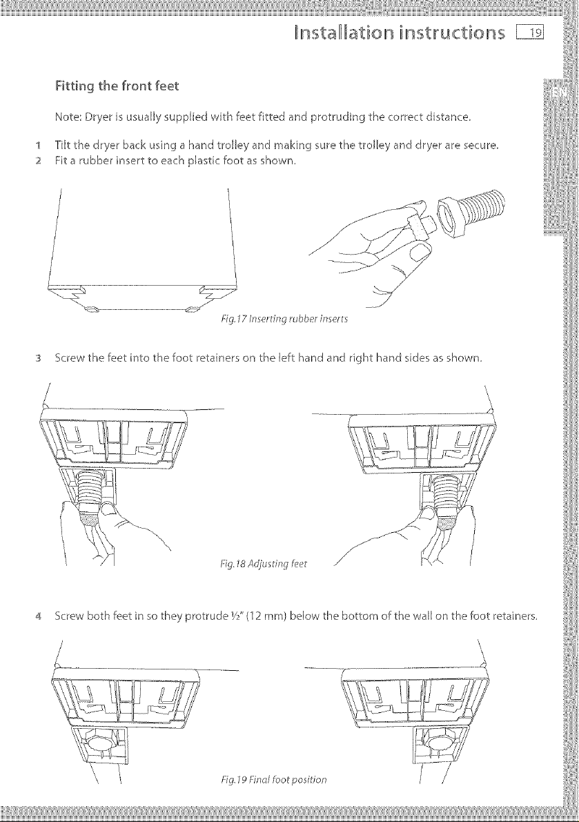
4 ScrewbothfeetinsotheyprotrudeVY'(12ram)bdowthebottomofthewaJJonthefootretainers,
Fig.19Fincdfool posidon
lnstalllLation instlructions
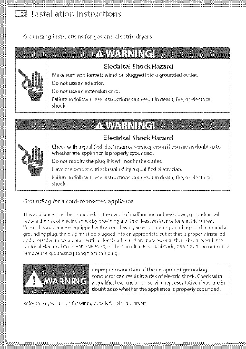
Grounding instructions for gas and electric dryers
EWectrka_ Shock Ha_rd
Make sure appliance is wired or plugged into a grounded out_et,,
Do not use an adaptor.
Do not use an extension cord.
Failure to follow these instructions can result in death, fire, or electrica_
shock
E_ectrka_ Shock Hazard
Check with a qualified e_ectrician or serviceperson if you a_e in doubt as to
whether the appliance is property grounded.
Do not modify the plug if it will not fit the out_et.
Have the proper outlet installed by a qualified electriciano
Failure to follow these instructions can result in death, fire. or e_ectrical
shock.
Grounding for a cord<onnected appliance
This appliance must be grounded. In the event of malfunction or breakdown, grounding will
reduce the risk of electric shock by providing a path of least resistance for electric current.
When this appliance is equipped with a cord having an equipment-grounding conductor and a
grounding plug, the plug must be plugged into an appropriate outlet that is properly installed
and grounded in accordance with all local codes and ordinances, or in their absence, with the
National Electrical Code ANSI/NFPA 70, or the Canadian Electrical Code, CSA C22.1. Do not cut or
remove the grounding prong from this plug.
Improper connection of _he equipmentogrounding
conductor can result in a risk of e_ectric shock. (beck with
a qualified electrician or service representative if you are in
doubt as to whether the appliance is properly grounded.
Refer to pages 21 - 27 for wiring details for electric dryers.
Illnstalllllation instlructions E]
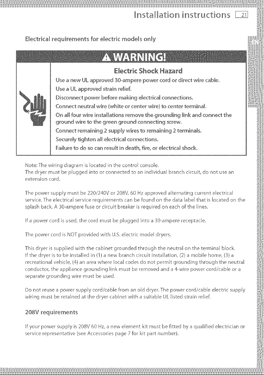
Electrical requirements for electric models only
Use a new UL approved 30-ampere power cord or direct wire came°
Use a UL approved strain relief.
Disconnect power before making e_ectrica_ connections,
Connect neutra_ wire (white or center wire) to center terminal
On aH four wire [ns_Hat[ons remove the grounding _ink and connect the
ground wire to the green ground connecting screw.
Connect remaining 2 supply wires to remaining 2 terminalso
Securely tighten a_me_ectrica_ connections,,
Failure to do so can result [n death, fire, or electrical shock.
Note: The wiring diagram is located in the control console.
The dryer must be plugged into or connected to an individual branch circuit, do not use an
extension cord.
The power supply must be 220/240V or 208V, 60 Hz approved alternating current electrical
service.The electrical service requirements can be found on the data label that is located on the
splash back. A 30-ampere fuse or circuit breaker is required on each of the lines.
If a power cord is used, the cord must be plugged into a 30-ampere receptacle.
The power cord is NOT provided with U.S. electric model dryers.
This dryer is supplied with the cabinet grounded through the neutral on the terminal block.
If the dryer is to be nstaJled in (1) a new branch circuit installation, (2) a mobile home, (3) a
recreational vehicle, (4) an area where local codes do not permit grounding through the neutral
conductor, the appliance grounding link must be removed and a 4-wire power cord/cable or a
separate grounding wire must be used.
Do not reuse a power supply cord/cable from an old dryer.The power cord/cable electric supply
wiring must be retained at the dryer cabinet with a suitable ULlisted strain relief.
208V requirements
if your power supply is 208V 60 Hz, a new element kit rnust be fitted by a qualified electrician or
service representative (see Accessories page 7 for kit part number).
nstalllBtion inst,ructions
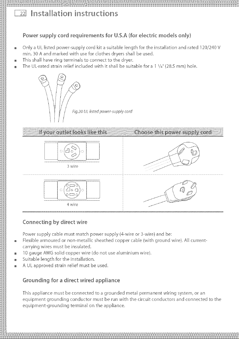
Power supply cord requirements for U°SA (for electric models only)
Only a UL listed power--supply cord kit a suitable length for the installation and rated 120/240 V
rain, 30 A and marked with use for dothes dryers shall be used.
This shall have ring terminals to connect to the dryer.
The Ubrated strain relief included with it shall be suitable for a 1 1/8"(28.S mm) hole.
Fig_20 ULIi£€*d power-supply cord
..................................lJ
3wire _ f
4 wire
Cormecdng by direct wire
Power supply cable must match power supply (4--wire or 3--wire) and be:
Flexible armoured or non--metallic sheathed copper cable (with ground wire), All current-
carrying wires must be insulated.
10 gauge A3b/Gsolid copper wire (do not use aluminium wire).
Suitable length for the installation,
A UL approved strain relief must be used.
Grounding for a direct wired appliance
This appliance must be connected to a grounded metal permanent wMng system, or an
equipment grounding conductor must be run with the circuit conductors and connected to the
equipment-grounding terminal on the appliance.

iiii}iilliiii ¸ii'ii¸ii'iiiiill¸iiilliiiii'}}}iillliii!i
IIInstalllllation insWuctions
Electrical connections (electric models only)
Please read Electrical requirements and grounding instructions on pages 20 - 21 fkst_
Electric models of the dryer are manufactured for a 3-wire connection system, The dryer frame
is grounded by a link to the neutral conductor on the dryer terminal block If local codes do
not permit grounding through the neutral, the grounding link from the terminal block must be
removed and a separate ground wire must be used,
The grounding link on the dryer must be removed for all &wire installations including new
remodelled construction, or mobile homes,
These Electrical Connection instructions provide for installing the dryer in the following
situations:
3--wire connection where local codes permit grounding through the neutral.
3-wire connection plus separate grounding connector where local codes do not permit
grounding through the neutral.
&wire connection.
Each of the above connections can be made with an approved power supply cord or by direct
wiring. Each connection instruction identifies the appropriate Power Supply Cord and covers
requirements for direct wiring.
For 3_-wire connections by power cords
3-wire power supply cord must have three 10 AWG copper wires and match a 3-wire receptacle
!
For 3owire connections by direct wiring
1O-gauge, 3wire with
ground wire (Romex)
14
,Ng.21 Wiring 3wire conneclions
i!iii_!_!_i!i!_li_l_lii_iiiiiiii_ii_li_i_iiii!iiii!i!ii!ili_iiil¸il¸il_iii_ii_iiii:iiii¸I¸iiiiiiii¸ii'lii¸iiiiiiiii'ii_iiliiiiiil¸il_ii_iii_li_i_liiiiiiiiil¸il¸ii'liiiii¸iiiiiiiiiiHi_i_iii_iii_i1i@iiiw@iii_iiii_ii@@;iiiiii_i_ii_i_i_i_i_ii_iiii1i_¸iiiil¸iiiil¸iiiil¸iiiil¸iiiil¸iiiil¸iiiil¸iiiil¸iiiil¸iiiil¸iiiil¸iiiil¸iiiil¸iiiil¸iiiil¸iiiil¸iiiil¸iiiil¸iiiil¸iiiil¸iiiil¸iiiil¸iiiil¸iiiil¸iiiil¸iiiil¸iiiil¸iiiil¸i_ili_li_i_iiii:iiiil¸liiiliiliiliiliiliiliiliiliiliiliiliiliiliiliiliiliiliiliiliiliiliiliiiiil
_t _nstalllati©n inst_ucti©ns
Electrical connections (electric models only}
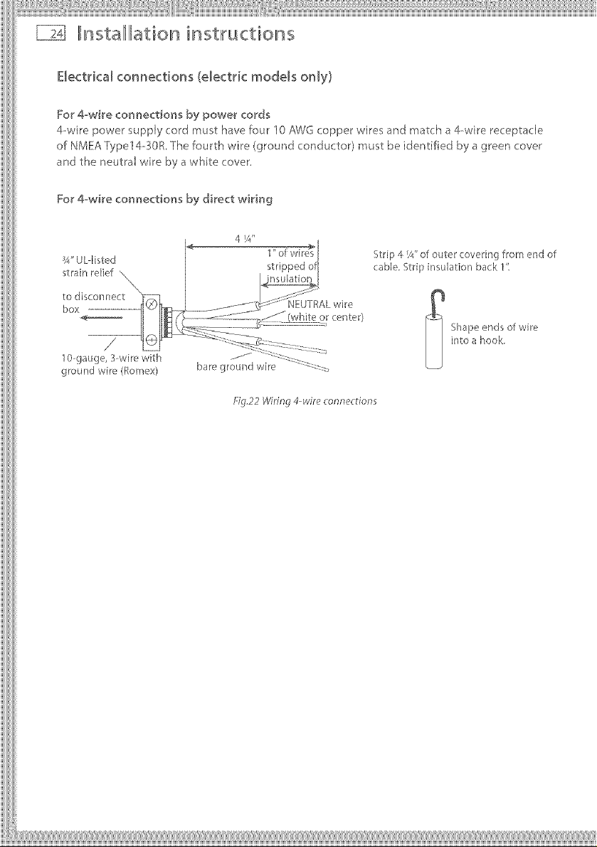
For #wire connections by power cords
4-wire power supply cord must have four 10 A}fTGcopper wires and match a 4-wire receptacle
of NMEA Type14--SOR The fourth wire (ground conductor) must be identified by a green cover
and the neutral wire by a white cover,
For 4wire connections by direct wiring
4 I/4"
Strip 4 ¼"of outer covering from end of
cable. Strip insulation back 1':
Shapeends of wire
into a hook.
ground wire (Eomex)
f:/g.22 Wiring 4wire connedions
Illnstallllationinst,ructions E]
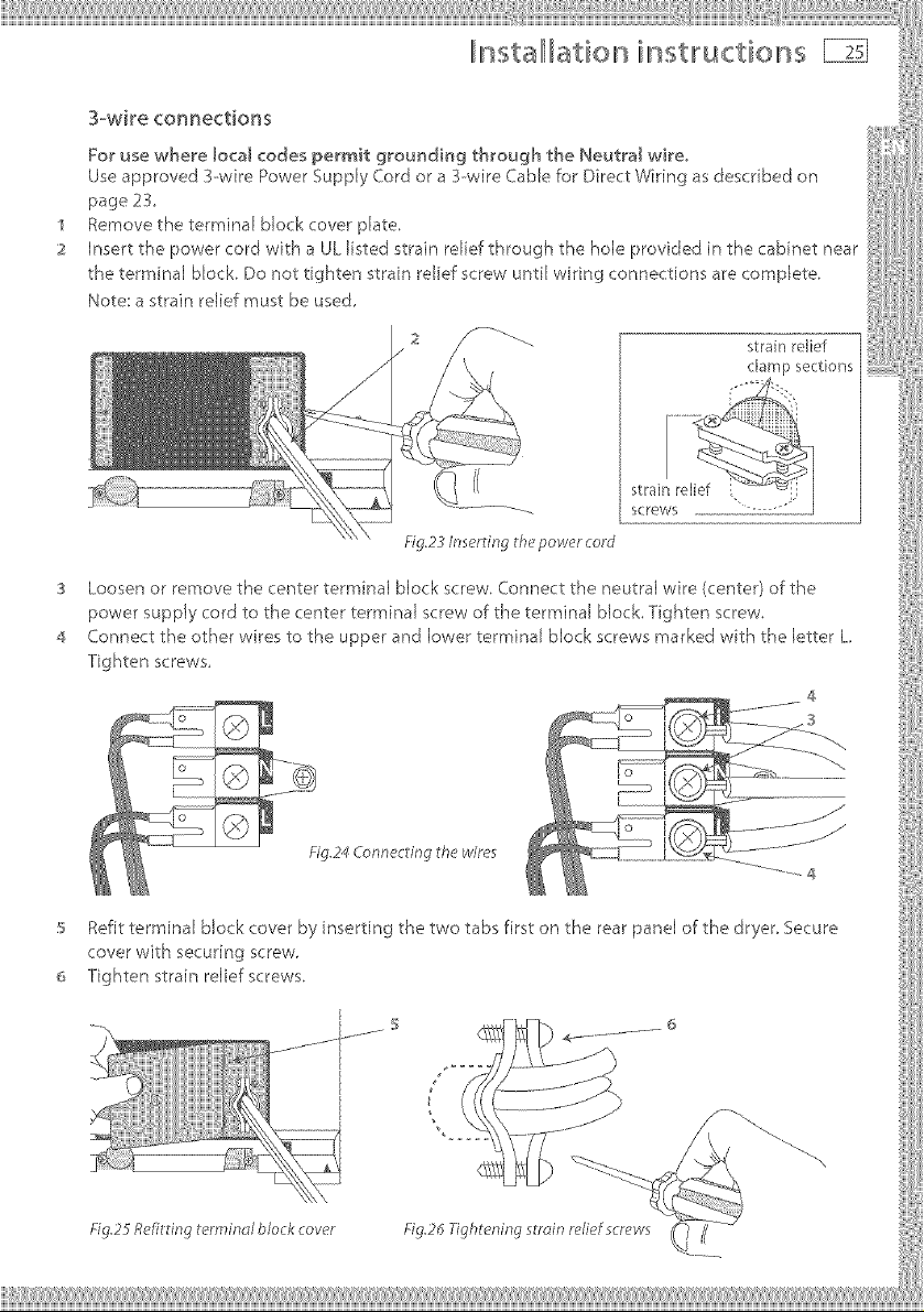
3_wi_e connections
For use where [oca[ codes permit grounding through the Neutra[ wire°
Use approved I--wire Power Supply Cord or a 3--wire CaNe for Direct Wiring as described on
page 23,
Remove the terminal block cover plate.
Insert the power cord with a UL listed strain relief through the hole provided in the cabinet near
the terminal block. Do not tighten strain relief screw until wiring connections are complete,
Note: a strain relief must be used,
strain relief
damp sections
SCreWS - --
3
Loosen or remove the center terminal block screw, Connect the neutral wire (center) of the
power supply cord to the center terminal screw of the terminal block, Tighten screw.
4
Connect the other wires to the upper and lower terminal block screws marked wth the letter L
Tighten screws,
4
3
Fig.24 Conneding lhe wires
_ Refit terminal block cover by inserting the two tabs first on the rear panel of the dryer, Secure
cover with securing screw.
6 Tighten strain relief screws,
Fig.25 Ref'ildng terminol blo k cover Fig.J* Tightening s_min relief screws
lnsta[lllati©n inst 'uctions
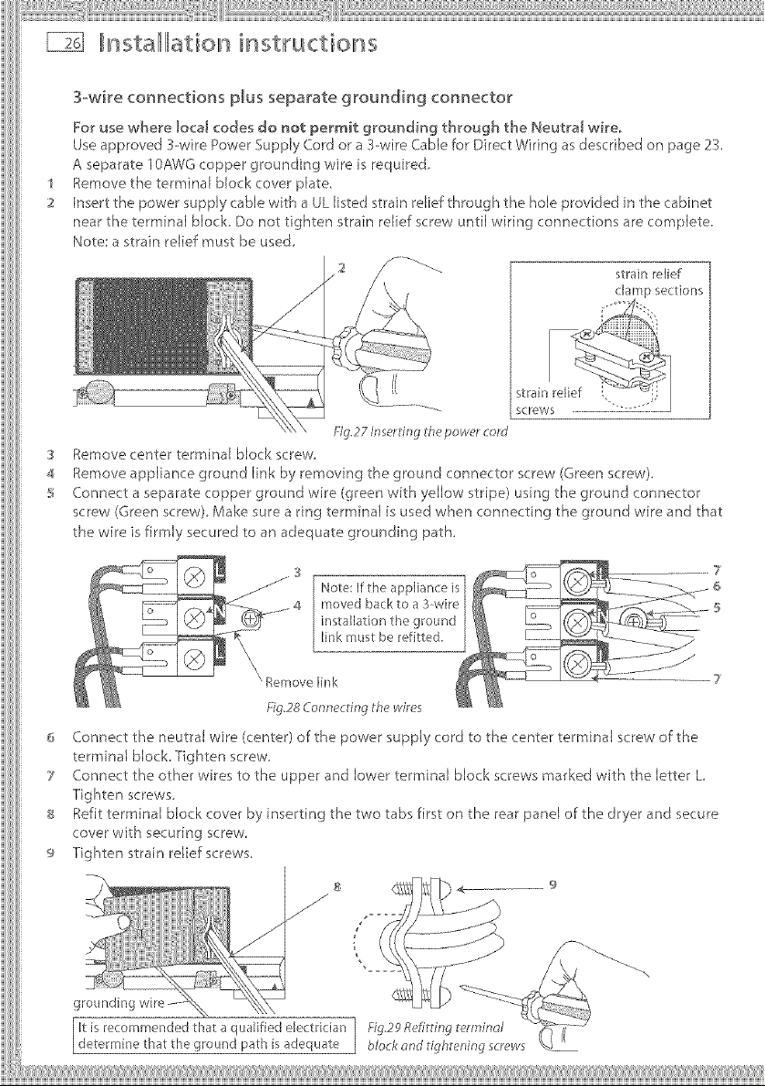
3-wire connections plus separate grounding connector
For use where local codes do not permit grounding through the Neutral wire.
Useapproved 3wife PowerSupply Cordor a 3--wireCablefor DirectWiring asdescribed on page 2X
Aseparate ]0AWGcopper grounding wire isrequired,
Removethe terminal block cover plate,
Insert the power supply cable wkh a ULlisted strain relief through the hob provided inthe cabinet
near the terminal biocL Do not tighten strain relief screw until wiring connections are complete.
Note astrain relief must be used
strain relief
clamp sections
Fig.27 Inserling 8hepowercord
Removecenter terminal block screw.
3
4
Removeappliance ground link by removing the ground connector screw (Greenscrew).
S
Connect a separate copper ground wire (green with yellow stripe) using the ground connector
screw (Greenscrew).Make sure a ring terminal is usedwhen connecting the ground wire and that
the wire isfirmly secured to an adequate grounding path.
S
Note: If the appliance is
moved back to a 3wire
installation the ground
link must be refitted,
\ Remove link 7
FYg,28Connecting th_ wir_*s
Connect the neutral wire (center) of the power supply cord to the center terminal screw of the
terminal block.Tighten screw.
7 Connect the other wires to the upper and lower terminal block screws marked with the letter L
Tighten screws.
8 Refit terminal block cover by inserting the two tabs first on the rear panel of the dryer and secure
cover with securing screw
9 Tighten strain relief screws
8
.//j/
J
/
It is recommended that a qualified ,4ectriclan 1 ig.2g R_filting _ennind
delermine that the ground path is adequate ] block ond tightening screws
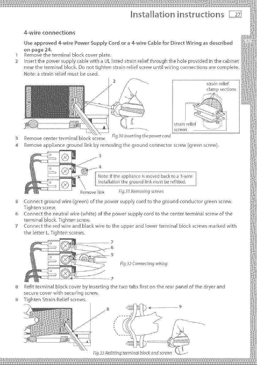
4,_wi_e co_ectio_s
Remove the terrninal block cover plate. _ 'i
Insert the power supply cable with a UL listed _train relief through the hole provided in the cabinet
near the terminal block Do not tighten strain relief screw until wiring connections are complete,
Note', a strain relief must be used,
sorrows
Remove center terminal block screw, ig._o Inserling lhe power cord
Remove appliance ground link by removing the ground connector screw (green screw),
3
4
I No_e:lf_he appliance is moved backtoa 3wire ]
lns_aJlationtha ground link must be lefi_ted.
Remove link ig._'/Removing screws
S Connect ground wire (green) of the power supply cord to the ground conductor green screw,
Tighten screw,
_ Connect the neutral wire (white) of the power supply cord to the center terminal screw of the
terminal block Tighten screw,
7 Connect the red wire and black wire to the upper and lower terminal block screws marked with
the letter L Tighten screws
]
Fig._;2 Connect ng wiring
7¸
_ Refit terminal block cover by inserting the two tabs first on the rear panel of the dryer and
secure cover with securing screw,
(_ Tighten Strain Relief screws,
Fig,33Refitdng terminal block_nd screws
_t
,L stalllatio ilnst 'uctior s
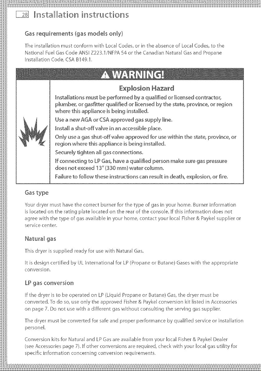
Gasrequiremertts (gas models ordy}
The installation must conform with Local Codes, or in the absence of Local Codes, to the
National Fuel Gas Code ANSI Z223,1/NFPA 54 or the Canadian Natural Gas and Propane
Installation Code, CSA B14g.l.
Explosion Ha_rd
_nstaHations must be performed by a qualified or _icensed contractor,
p_umber, or gasfitter qualified or _icensed by the state, province, or region
where this appliance is being instaHedo
Use a new AGA or CSA approved gas supply _ineo
Install a shut-offva[ve in an a<cessib[e p[aceo
Only use a gas shut-off valve approved for u_ within the state, province, or
region where this appliance is being instaHedo
Securely tighten aH gas connections.
_fconnecting to LP Gas, have a qualified person make sure gas pressure
does not exceed 13"(330 ram} water co_umno
Failure to follow these instructions can result in death, explosion, or fire.
Gas type
'four dryer must have the correct burner for the type of gas in your home. Burner information
is ocated on the rating plate located on the rear of the console. [f this information does not
agree with the type of gas available in your home, contact your local Fisher & Paykel supplier or
service center.
This dryer is supplied ready for use with Natural Gas.
It is design certified by UL International for LP (Propane or Butane) Gases with the appropriate
conversion,
LPgas conversion
If the dryer is to be operated on LP (Liquid Propane or Butane) Gas, the dryer must be
converted. To do so, use only the approved Fisher & Payke[ conversion kit listed in Accessories
on page 7. Do not use with a different gas without consulting the serving gas supplier.
The dryer must be converted for safe and proper performance by qualified service or installation
personek
Conversion kits for Natural and LPGas are available from your local Fisher & Payke[ Dealer
(see Accessories page 7) If other conversions are required, check with your local gas utility for
specific information concerning conversion requirements.
 Loading...