

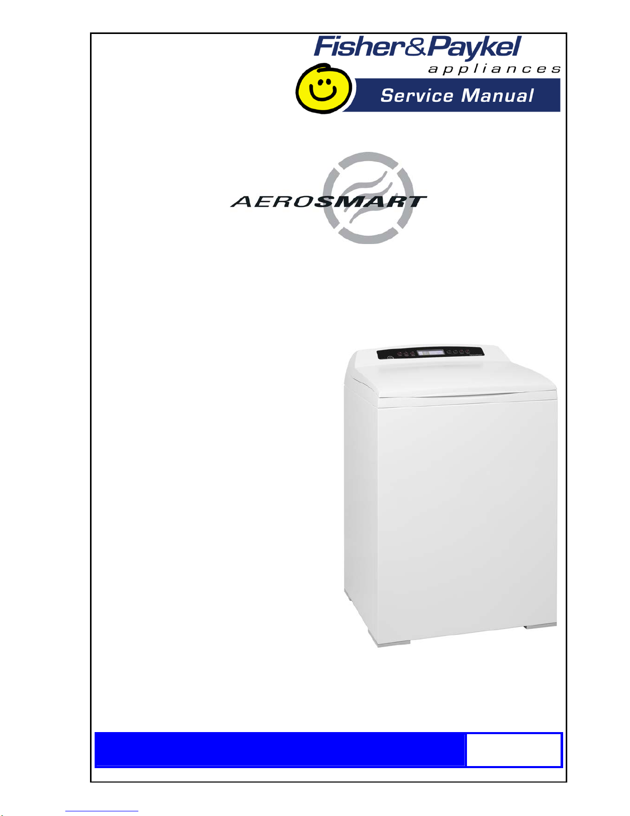
Fisher & Paykel AeroSmart DE62T27CW1, AeroSmart DG62T27CW1, AeroSmart DE62T27DW1, AeroSmart DG62T27DW1 Servlce Manual
Page 1
517760C
Models
DE62T27CW1
DG62T27CW1
DE62T27DW1
DG62T27DW1
Supplementary to 517760B
Page 2

517760C
2
Page 3

517760C - APRIL 2007 REPRINT - AUGUST 2007
Fisher & Paykel Appliances Inc
5800 Skylab Road
Huntington Beach
CA 92647
USA
Phone: 1 888 936 7872
3
The specifications and servicing procedures outlined in this manual are subject to change without
notice.
The latest version is indicated by the reprint date and replaces any earlier editions.
Note: This supplementary manual is only to be used in conjunction with service manual
517760B. It is not intended to be used on its own.
Page 4

517760C
4
CONTENTS
1 SERVICING REQUIREMENTS................................................................................................5
1.1 Health & Safety...............................................................................................................5
1.2 Electrical Safety ..............................................................................................................5
1.3 Electrostatic Discharge ...................................................................................................5
1.4 Good Working Practices .................................................................................................5
1.5 Safety Test......................................................................................................................5
1.6 Sheet Metal Edges..........................................................................................................5
2 MODELS INFORMATION........................................................................................................6
2.1 Models Number...............................................................................................................6
2.2 Serial Number.................................................................................................................6
2.3 Product Code..................................................................................................................7
3 TECHNICAL OVERVIEW ........................................................................................................7
3.1 Finish ..............................................................................................................................7
3.2 Electrical Supply..............................................................................................................7
3.3 Dimensions .....................................................................................................................7
3.4 Maximum Capacity (Full Load) .......................................................................................7
4 COMPONENTS........................................................................................................................8
4.1 Control Panel Assembly..................................................................................................8
4.2 Fascia .............................................................................................................................9
5 SERVICE PROCEDURES.....................................................................................................10
5.1 Removal of Lid..............................................................................................................10
5.2 Removal of Console......................................................................................................10
5.3 Removal of Display Module ..........................................................................................10
6 DIAGNOSTICS ......................................................................................................................11
6.1 Overview – LCD Models ...............................................................................................11
6.2 Overview – LED Models................................................................................................11
6.3 Fault Code Summary....................................................................................................12
7 DIAGNOSTIC MODE – LCD MODELS .................................................................................16
7.1 Entering the Diagnostic Mode.......................................................................................16
7.2 Service Screen..............................................................................................................16
7.2.1 Fault Status Screen..............................................................................................16
7.2.2 Machine Status Screen........................................................................................17
7.2.3 Warning Status Screen........................................................................................17
7.3 Testing the Conductivity Contacts.................................................................................17
7.4 Data Download Mode....................................................................................................17
7.5 Showroom Mode...........................................................................................................18
8 DIAGNOSTIC MODE – LED MODELS .................................................................................18
8.1 Entering the Diagnostic Mode.......................................................................................18
8.2 Testing the Conductivity Contacts.................................................................................19
8.3 Show Room Mode ........................................................................................................19
8.4 Data Download Mode....................................................................................................19
9 AUTOSENSING.....................................................................................................................19
10 TEMPERATURE CONTROL .................................................................................................19
11 COOL DOWN.........................................................................................................................20
12 CYCLE CHARTS – LCD MODELS .......................................................................................21
12.1 Electric.....................................................................................................................21
12.2 Gas ..........................................................................................................................23
13 CYCLE CHARTS – LED MODELS........................................................................................25
13.1 Electric.....................................................................................................................25
13.2 Gas ..........................................................................................................................25
14 WIRING DIAGRAM – ELECTRIC MODELS .........................................................................26
15 WIRING DIAGRAM – GAS MODELS....................................................................................27
Page 5

517760C
5
1 SERVICING REQUIREMENTS
1.1 Health & Safety
Note: When servicing the AeroSmartTM electronic dryer, health and safety issues must be
considered at all times. Specific safety issues are listed below to remind service people of
the health and safety issues.
1.2 Electrical Safety
WARNING! TO AVOID ELECTRIC SHOCK!
Do not attempt to service this dryer without suitable training and qualifications.
Ensure the mains power has been disconnected before servicing any part of the dryer. If the
power is required to be on for electrical fault finding, or checking the operation, then extreme care
should be taken not to make contact with electrical components other than with testing probes.
Ensure the dryer is turned off when removing any electrical component or connection.
1.3 Electrostatic Discharge
Electronic components are prone to damage from electrostatic discharges. The electronic
modules in this product contain no user serviceable components and breaking seals to access
internal components of an electronic module may void the product warranty. Avoid contact with
PCB edge connectors when handling electronic modules.
1.4 Good Working Practices
Ensure the work areas are kept tidy and free of hazards while servicing the dryer. On completion
of the servicing, ensure the dryer and work areas are left clean and tidy.
1.5 Safety Test
On completion of any service carried out to the dryer, all safety tests as required by law must be
carried out.
1.6 Sheet Metal Edges
When working around cut sheet metal edges use appropriate gloves or protection to eliminate the
chance of receiving a laceration.
Page 6
517760C
6
2 MODELS INFORMATION
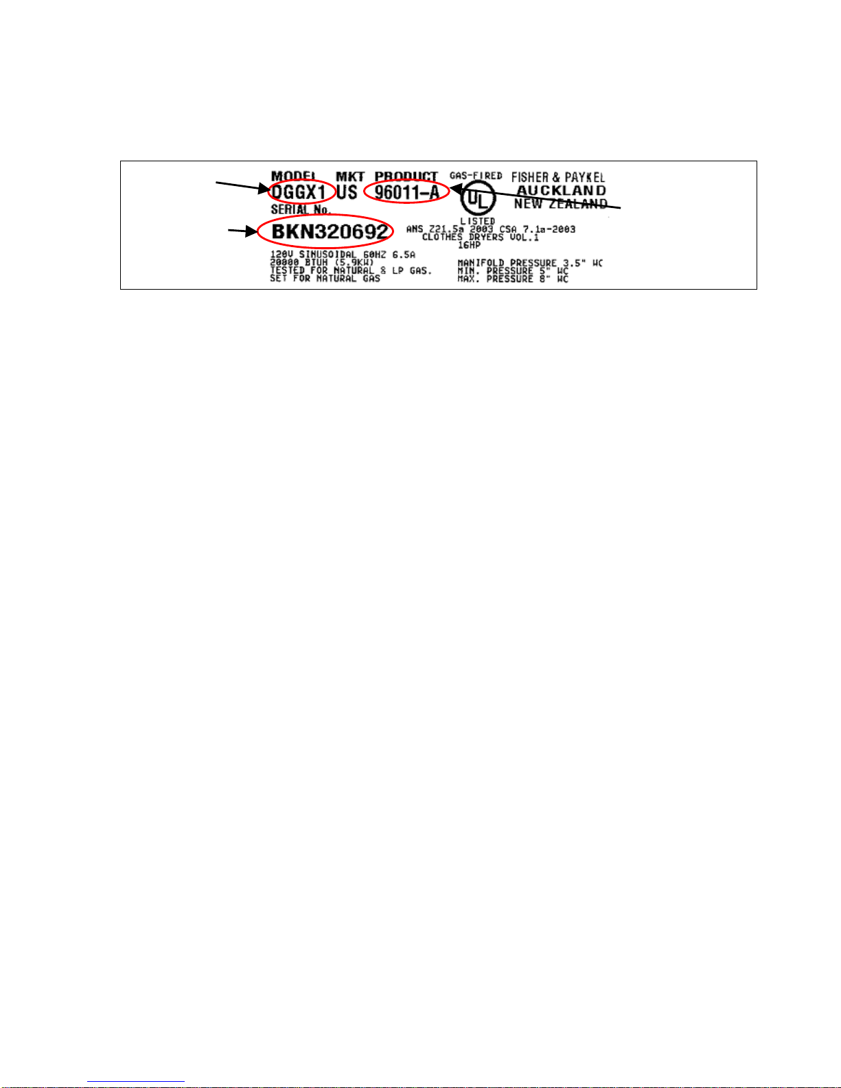
The product serial plate is located on the upper rear of the cabinet and contains the following
information:
2.1 Models Number
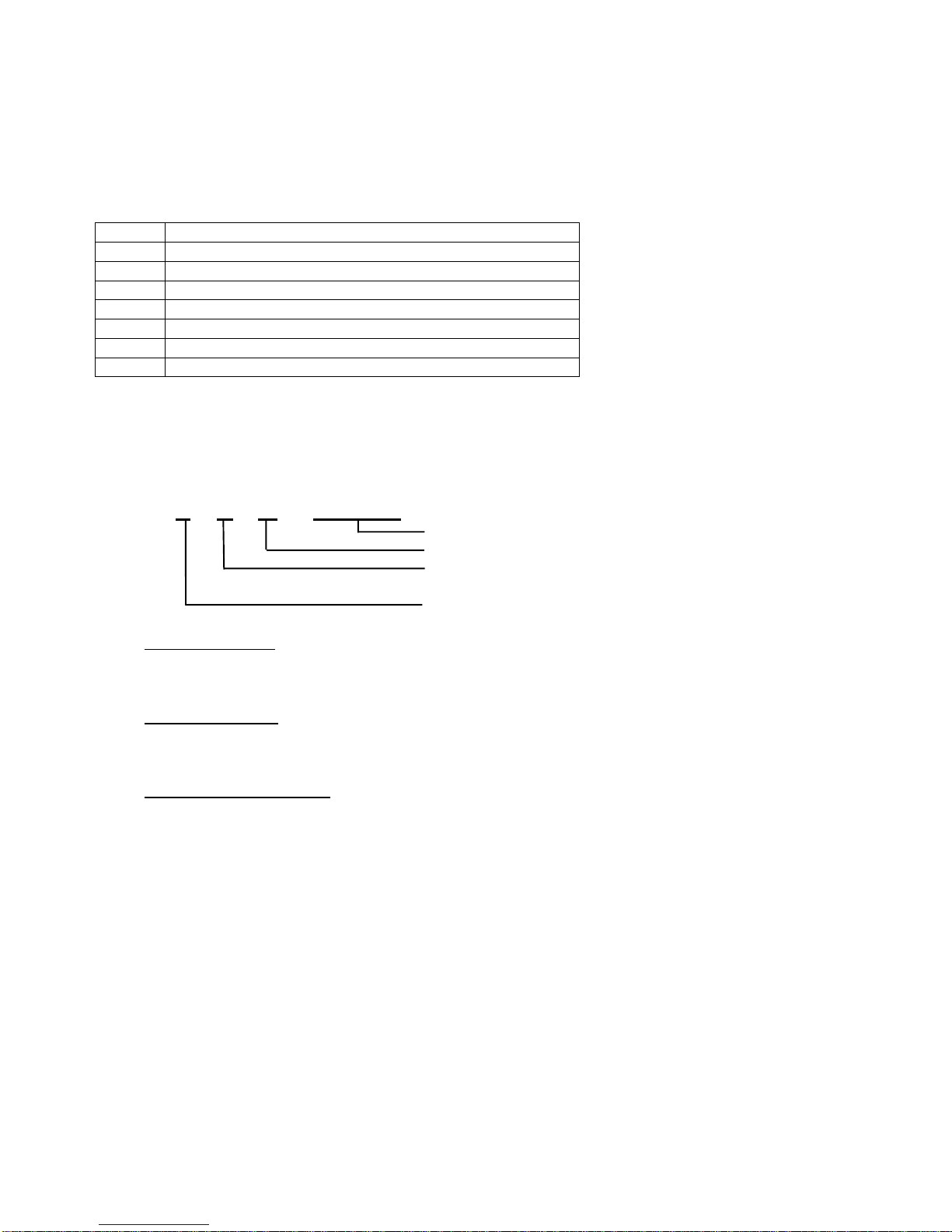
The models number contains the following information:
D
Product Type (Dryer)
E
Heating Type (E = Electric / G = Gas)
62
Capacity cu/ft (6.2) IEC
T
Top Loading
27
Size (27 inches wide)
C
Console (C = LCD / D = LED)
W
Color (White)
1
Series (1)
2.2 Serial Number
The serial number consists of three letters and six digits and contains the following information:
Example:
L F U 123456
Sequential Serial Number
Manufacturing Plant Code
FISHERPAYKUL Code indicates month of
manufacture
CUMBERLAND Code indicates year of manufacture
Cumberland Code
Letter C U M B E R L A N D
Year 1 2 3 4 5 6 7 8 9 0
Fisherpaykul Code
Letter F I S H E R P A Y K U L
Month 1 2 3 4 5 6 7 8 9 10 11 12
Manufacturing Plant Code
F Refrigeration – New Zealand
M Range & Dishwasher
N Laundry – New Zealand
Q Refrigeration – Australia
U Laundry – U.S.A.
In the example above, the appliance was manufactured in the first month of the seventh year
(2007) at the Laundry plant in Ohio (U.S.A.).
Page 7
517760C
7
2.3 Product Code
A suffix letter has been added to the Product Code. This suffix letter will change whenever a part
is changed that is not completely retro-fittable without the need for a kit, or whenever a cosmetic
change is made.
At the same time, separate parts manuals will be produced for each product code, making it easier
for the service technician to obtain the correct part for the appliance they are servicing. The part
number of the manual will be the same as the Product Code.
It is now important that the service technician obtains the Product Code from the serial plate of the
appliance before ordering parts, then refers to the appropriate parts manual to ensure that the
correct part numbers are obtained.
3 TECHNICAL OVERVIEW
3.1 Finish
Cabinet: Pre-paint (Polyester)
Touch-Up Paint: White #503086
Lid: ABS Co-injected, one piece
Console: ABS plastic
Facia (LCD Models): IMD (In-mould decorative) Polycarbonate/PET
Facia (LED Models): PC/PBT Printed film + clear ABS.
Drum: Stainless steel grade 430T
Top Deck: Polypropylene
3.2 Electrical Supply
Operating Voltage Maximum Current
USA Electric 220/240V AC 60Hz 24 Amps
USA Gas 110/120V AC 60Hz 6 Amps
3.3 Dimensions
Height to lid
Open 55 ½ in – 56 ¾ in 1410mm – 1440mm
Closed 36 ½ in – 37 ½ in 925mm – 955mm
Height to console 40 ¼ in – 41 ½ in 1020mm – 1050mm
Width 27 685mm
Depth 27 ½ in 700mm
Note: Exact height of the AeroSmart
TM
dryer is dependent on how far the feet are inserted
into the base of the dryer.
Weight Packed 152lbs (69kg)
Unpacked 134 lbs (61kg)
3.4 Maximum Capacity (Full Load)
Drum Volume 6.2 cubic feet (.184 cubic meters)
Model
Serial
Page 8
517760C
8
4 COMPONENTS
The only visual change of major components between the G (General), I (Intuitive™) and the
AeroSmart™ dryer is with the console assembly.
The Aerosmart™ LCD models incorporates an IMD (In-mould decorative display), which uses
capacitive touch buttons that sense the user’s fingers over the buttons. It has a large LCD Display
allowing us to show graphics on the screen. The new screen allows us to present information
simply while providing a lot more detail, such as graphic icons, pop up explanations and
confirmation.
The AeroSmart™ LED models incorporates backlit buttons, with the selected button illuminated
more brightly than the others. Words indicating selections made are also illuminated.
4.1 Control Panel Assembly
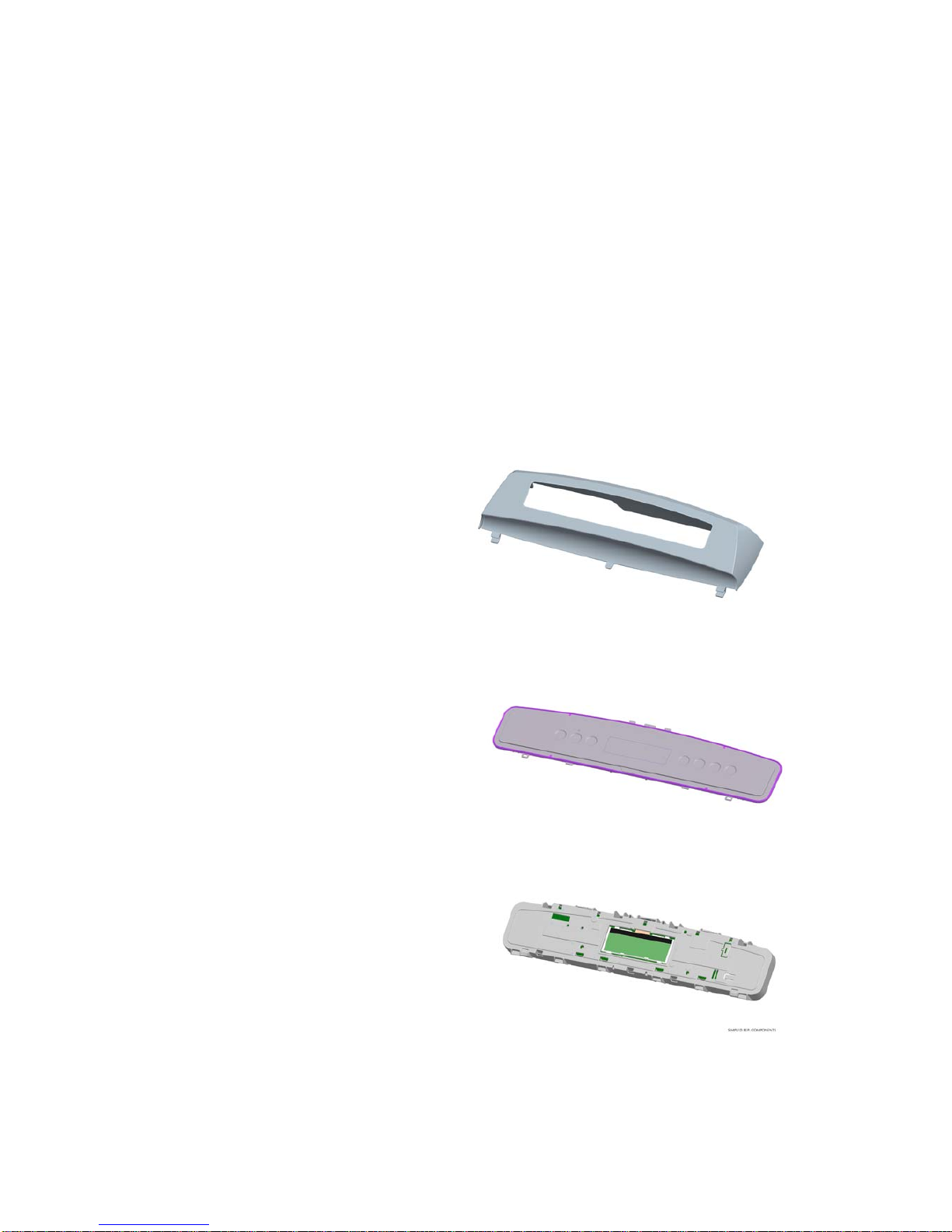
The three core components of the control panel assembly are the console, the fascia, and the PCB
and housing.
Console
The console, which is made from ABS is the
housing to which the fascia and PCB housing
attaches. Lugs at the base of the console
locate into the top deck. The console is secured
to the rear of the top deck by two screws.
Fascia
The fascia will be one of either the IMD fascia
for LCD models or the touch panel for LED
models.
PCB and Housing
The PCB, which contains the electronics, is
mounted within a plastic housing. The PCB
housing is clipped into the console at the
bottom, and secured with four screws along the
top.
Page 9
517760C
9
4.2 Fascia
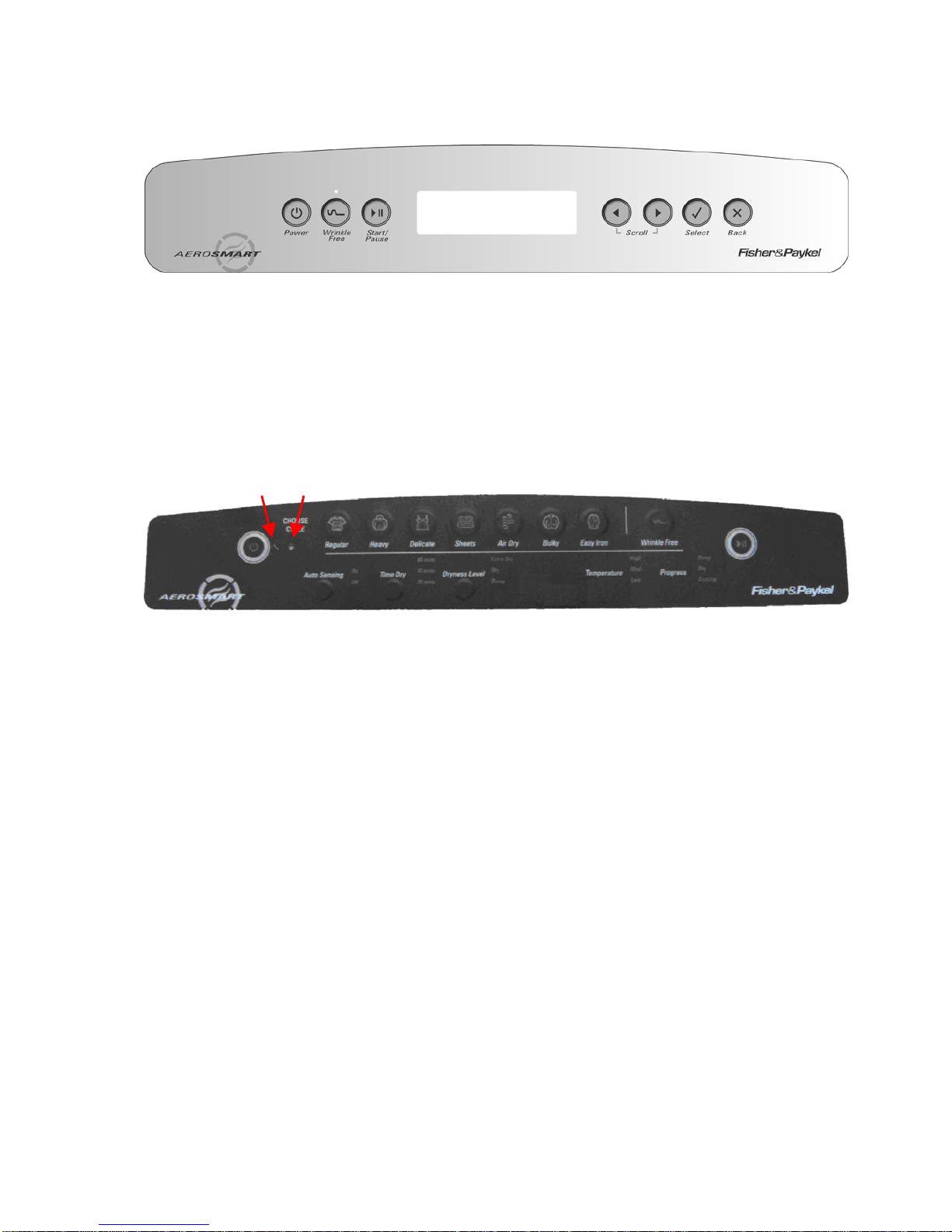
LCD Models
1. Power On/Off button.
2. Wrinkle Free On/Off. When the LED is on the wrinkle free option is turned on.
3. Wrinkle Free LED used also for data download (Refer to Section
7.4).
4. Start/Pause button.
5. LCD Screen.
6. Left arrow (used when scrolling through options on the LCD screen).
7. Right arrow (used when scrolling through options on the LCD screen).
8. Select button – Use to confirm setting.
9. Back button – Use to cancel setting.
LED Models
1. Power button. 10. Bulky button.
2. Auto Sensing button. 11. Air Dry button.
3. Time Dry button. 12. Sheets button.
4. Dryness Level button. 13. Delicate button.
5. Temperature. 14. Heavy button.
6. Progress. 15. Regular button.
7. Start/Pause button. 16. Lid Lock icon.
8. Wrinkle Free button. 17. Service Spanner icon.
9. Easy Iron button.
1
2
5
6
7
8
9
3
4
1
2 3 4 5 6
7
15 14 13 12 11 10 9 8 17 16
Page 10
517760C
10
5 SERVICE PROCEDURES
Note: These instructions refer to the removal of the display module only. Refer to Service
Manual 517760B for full servicing instructions.
Note: Prior to carrying out any service procedures ensure that the machine has been
isolated from the power supply.
To remove the display module, follow the procedures as detailed below.
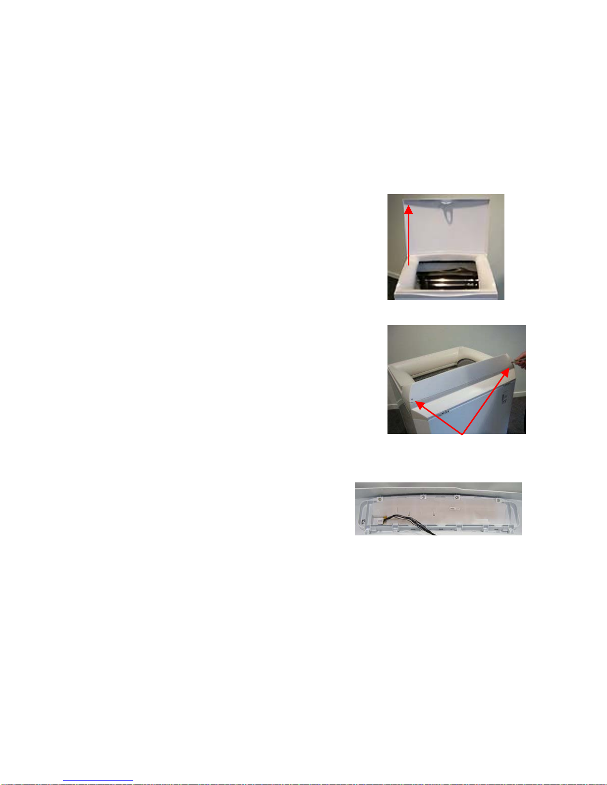
5.1 Removal of Lid
(a) Open the lid fully, then lift off vertically.
Reassembly
Refit in reverse manner, ensuring that the hinge lugs on the lid are
vertical.
5.2 Removal of Console
(a) Disconnect the unit from the power supply.
(b) Remove the lid.
(c) Remove the two screws at the rear of the console securing the
console to the top deck.
(d) Tilt the console forward.
Reassembly:
Refit in reverse manner.
5.3 Removal of Display Module
(a) Follow procedures for removal of console (refer to
Section
5.2).
(b) Disconnect the wiring harness from the sensor module.
(c) Remove the 4 screws securing the display module to
the console
(d) Remove the display module from the housing by
pivoting the display away from the console.
Reassembly:
Refit in the reverse manner.
Lift
Screws
Page 11

517760C
11
6 DIAGNOSTICS
6.1 Overview – LCD Models
If a fault occurs that prevents correct operation
of the dryer, and is detected by the controllers,
the dryer is stopped, the LCD shows a fault
code and the beeper is continuously turned on
and off.
Pressing any button once will disable the
beeping. The fault code information will remain
on the LCD screen until the power supply to the
dryer is turned off.
If the Dryer has been either turned off or isolated from the power supply, the fault code can be
recalled from memory by entering diagnostic mode. (Refer to Section
7.1).
If START/PAUSE is pressed while the fault code is displayed, the beeping will stop and the optical
download is activated. (Refer to Section
7.4).
User Warnings
In the case of User Warnings, the LCD screen will display the User Warning and the beep tone will
change from a continuous tone to a musical series of beeps, which are repeated every 5 seconds.
Depending on the nature of the User Warning, the operation of the dryer may cease or continue to
‘limp on’ until the cycle finishes or the user intervenes.
Pressing the POWER button when a User Warning is displayed will immediately turn the dryer off.
User Warnings are saved to memory as Fault Codes, and the last Fault Code will be permanently
stored.
The warning will also be recorded in the Warning Status screen (refer to Section
7.2.3), however
the information on this screen will only be stored for as long as power is supplied to the dryer.
When the dryer is isolated from the supply, the information in this screen will be erased.
6.2 Overview – LED Models
If a fault occurs that prevents correct operation of the dryer, and is detected by the controllers, the
dryer is stopped, the LEDs flash showing a fault code and the beeper is continuously turned on
and off.
Pressing any button once will disable the beeping. The fault code information will remain in
memory.
If the Dryer has been either turned off or isolated from the power supply, the fault code can be
recalled from memory by entering diagnostic mode. (Refer to Section
8.1).
If START/PAUSE is pressed while the fault code is displayed, the beeping will stop and the optical
download is activated. (Refer to Section
8.4).
Page 12

517760C
12
User Warnings
There are two possible user warnings.
1. The machine is beeping and the lidlock light is flashing:
Close the lid and press Start/Pause.
If the lid is already closed, open and close it again, then press Start/Pause.
Disconnect from the power (either by unplugging the dryer or turning off at the power
supply). Wait 10 seconds. Reconnect and try turning the dryer on again.
2. The machine is beeping and the Time Dry 20 min is flashing:
The machine is unable to close the drum due to clothes interfering with the closing
mechanism. Remove any articles that are interfering with the drum door and dry these in
the next load.
Is the load higher than the lint bucket? Remove some articles and dry these in the next
load.
6.3 Fault Code Summary
The following are the fault codes that may be displayed. The remedy section of each fault is the
suggested sequence of repair or replacement. If the first suggestion does not remedy the fault,
check the next on the list.
Fault Code 1 Communications Error.
Communications failure between the sensor module and motor control module.
Remedy: (1) Check the continuity of the module interconnecting harness.
(2) Replace the sensor module.
(3) Replace the motor control module.
Fault Code 2 Drum Gap Cannot be Located.
Remedy: (1) Ensure the sensor module is correctly located and clipped into place.
(2) Replace the sensor module.
(3) Remove the top deck and clean the drum sensing “bumps” on the outside of
the drum end.
(4) Replace the drum.
Fault Code 3 Drum Stalled.
Remedy: (1) If there is mechanical movement of the drum, but this fault code is appearing,
follow the procedures for fault code 2.
(2) If there is no mechanical movement of the drum, check drum movement
mechanisms: belt, motor and motor harness.
(3) Replace the motor control module.
(4) Replace the motor.
Fault Code 4 Invalid Option Link Read.
The motor control module heat source option link read is invalid.
Remedy: Replace the motor control module.
Fault Code 6 Door Jammed – (User Warning).
The door is unable to close due to either clothes catching or an excessive closing load.
Remedy: (1) Remove the obstruction.
(2) Reposition or remove some of the load.
(3) Fix the cause of binding in the door closing mechanism.
(4) Replace the motor.
Page 13

517760C
13
Fault Code 7 Motor Current Excessive.
Remedy: (1) Free up the dryer. Remove overload or cause of jamming.
(2) Replace the motor control module.
(3) Replace the motor.
Fault Code 7b Display Module RAM Check Error (LCD Models only)
On power up, the display has checked its memory against a known reference and found
differences.
Remedy: Replace the display module.
Fault Code 8 Exhaust Sensor Over Temperature.
The exhaust sensor measures over temperature (element short circuit or low resistance).
Remedy: (1) Check the integrity of the sensor circuit, checking particularly for short
circuits. Approximate resistances (+
10%) at various temperatures are; 32oF
= 33 kOhms, 72
o
F = 11 kOhms, 104oF = 5 kOhms. Replace thermistor and
harness if out of range.
(2) Check the element integrity, in that it switches off when the dryer is stopped.
(3) Replace the motor control module.
(4) Replace the sensor module.
Fault Code 9 Exhaust Sensor Under Temperature.
The exhaust sensor measures under temperature (open circuit or not plugged in).
Remedy: Refer to steps for over temperature fault (fault code 8) above, but open circuit
likely.
Fault Code 10 24 Volt Supply Measurement Error.
The sensor module measures low voltage on actuator power supply.
Remedy: Replace the sensor module.
Fault Code 11 Lid Lock Open Circuit.
Remedy: Check the lid lock harness and coil. If there is continuity through these, replace
the sensor module.
Fault Code 12 Lid Lock Switching Device Failure.
Remedy: Check that there are no short circuits in the lid lock circuit which may have
caused the failure in the sensor module. The resistance of the lid lock should be
between 50 and 100 ohms. If the circuit is correct, replace the sensor module.
Fault Code 14 Sensor Module Fault.
Remedy: Replace the sensor module.
Fault Code 15 Sensor Module Fault.
Remedy: Replace the sensor module.
Fault Code 16 Airflow Restriction – (User Warning).
Airflow restriction.
Remedy: (1) Check that the lint bucket is empty and the filter is clear.
(2) Ensure that the exhaust duct is not restricted, blocked or kinked, preventing
good airflow.
(3) Ensure that there is nothing inhibiting unrestricted airflow through the heater
housing, through the drum, lint filter, lint collector and through the exhaust
duct, and that the element has not shorted. If the dryer is located in a closet,
ensure there is adequate ventilation for air intake.
(4) Check that the voltage is not too high.
(5) Check for element shorts or low resistance.
(6) Replace the automatic thermostat.
(7) Replace the motor control module.
Page 14

517760C
14
Fault Code 20 Door Actuator Stalled.
Remedy: As per fault code 21.
Fault Code 21 Door Actuator Required Excess Voltage.
Remedy: (1) Ensure there is no weight placed on the lid of the product (e.g. clothes
basket). If so, remove the weight and retest.
(2) Inspect the installation, making sure that the cabinet sits evenly on the floor.
If excess load is placed on the cabinet, it can cause the sub-deck assembly
to twist.
(3) Inspect the front inside edge of the top deck for any signs of excessive
inwards bowing, as this can cause it to catch on the door grabber, resulting
in excess current draw on activation. The bowing can be caused by a bowed
top deck or by incorrect assembly of the top deck to the cabinet front.
(4) Ensure the user intervention tab is not inhibiting door grabber movement.
(5) Check that the actuator linkage is located correctly. There must be no gap
between the linkage and the plastic moulding.
(6) Check that the actuator housing is in place, and that the four retaining lugs
are correctly located. Early models may have aluminium tape holding the
housing in place. If so, ensure that the tape is replaced when the housing is
refitted.
(7) Remove the actuator housing and look for obvious signs of things that are
out of position (can the worm drive be rotated freely both backwards and
forwards by hand, is the actuator motor in place?)
(8) Replace the faulty door actuator mechanism.
(9) Replace the door grabber, linkage and housings.
(10) Replace the sensor module.
Fault Code 22 Door Actuator Open Circuit.
Remedy: (1) Check that the actuator wiring is plugged into the sensor module and is not
open circuit. If faulty, replace.
(2) Replace the sensor module.
Fault Code 23 Door Actuator Movement Interrupted By Low Voltage.
The door actuator movement was interrupted by low voltage (brown out).
Remedy: (1) Ensure mains voltage is within +10% and –15% of nominal.
(2) Replace the sensor module, as voltage measurement circuit may be reading
incorrectly.
(3) Replace the motor control module, as it may not be supplying sufficient
power to the sensor module. When the display is off, approximately 24V DC
is supplied.
Fault Code 24 Door Actuator Movement Took Too Long.
Remedy: As per fault code 21.
Fault Code 28 Data Retrieval Error Following Loss of Power
Remedy: (1) Switch off the mains power supply to the dryer for at least 10 seconds and
confirm the error.
(2) Replace the motor control module.
Fault Code 29 Brown-Out Data Retrieval Error.
Remedy: (1) If the fault occurs every time the dryer is turned on, replace the sensor
module.
(2) Replace the motor control module.
Page 15

517760C
15
Fault Code 30 Lid Lock unable to Lock – (User Warning).
Reason: The lid lock failed to lock. (Not user displayed.)
Remedy: (1) Ensure the lid is closed and the tongue engaged.
(2) Replace the lid lock harness.
(3) Replace the lid lock.
(4) Replace the sensor module.
Fault Code 45 Display Module ROM Check Error
On power up, the display has checked its memory against a known reference and found
differences.
Remedy: Replace the display module.
Fault Code 105 Comms Error Time Out
Communications failure between the sensor module and display module.
Remedy: (1) Visually check the contacts on the RAST (edge) connector at each end on
the harness between the sensor module and display module.
(2) Using a multimeter, check for continuity of the wires in this harness.
(3) Replace the display module.
(4) Replace the sensor module.
Fault Code 233 EEPROM Read Error (LCD models only)
The sensor module has problems reading the EEPROM data in the display module.
Remedy: Replace the display module.
Notes:
1. If the dryer has stopped mid cycle with the Wrinkle Free LED illuminated, the LCD
screen (LCD models) or display LEDs (LED models) blank, and no fault "beeps", the
dryer may be experiencing a low voltage supply. At such a level the dryer cannot
function. Once the line voltage returns to normal, the dryer will recommence the
interrupted cycle.
2. If the power supply has been turned off, the dryer may momentarily display the state
described in Note 1 prior to fully shutting down.
Page 16
517760C
16
7 DIAGNOSTIC MODE – LCD MODELS
7.1 Entering the Diagnostic Mode
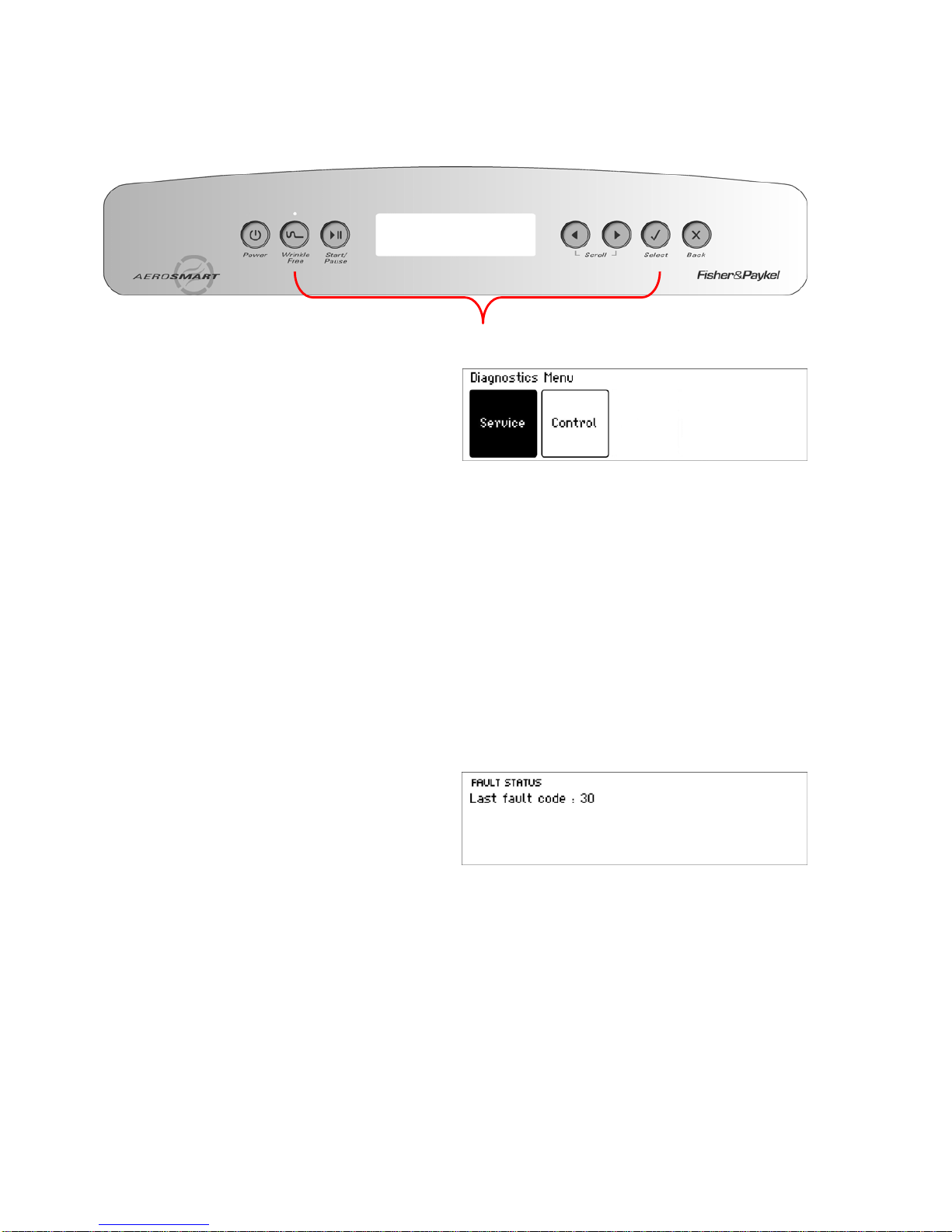
To enter the DIAGNOSTIC MODE, turn the
power on at the power point and off at the
console.
Press and hold the WRINKLE FREE button and then press the SELECT button. Keep the buttons
pressed for at least 2 seconds, after which time two beeps will sound and the screen above will
appear. Press the SELECT button again to enter the service screen.
Note: Provided the power supply to the machine is switched on, diagnostic mode may be
entered at any time. To exit from the Diagnostic Mode at any time, press POWER
7.2 Service Screen
Upon entering the service screen, one of the following screens will appear:
• Fault Status
• Machine Status
• Warning Status
To scroll between the screens, use the left and right arrows.
7.2.1 Fault Status Screen
Fault Status Screen
This screen will indicate the last fault code that
occurred. If a fault is registered, the fault code
is saved to EEPROM, which retains its memory
even when the power is switched off. The fault
code will remain visible until another fault code
overwrites it.
Note: Fault codes 7b, 45, and 105 will be reset if the power is switched off.
Press & Hold for 2 seconds
Page 17
517760C
17
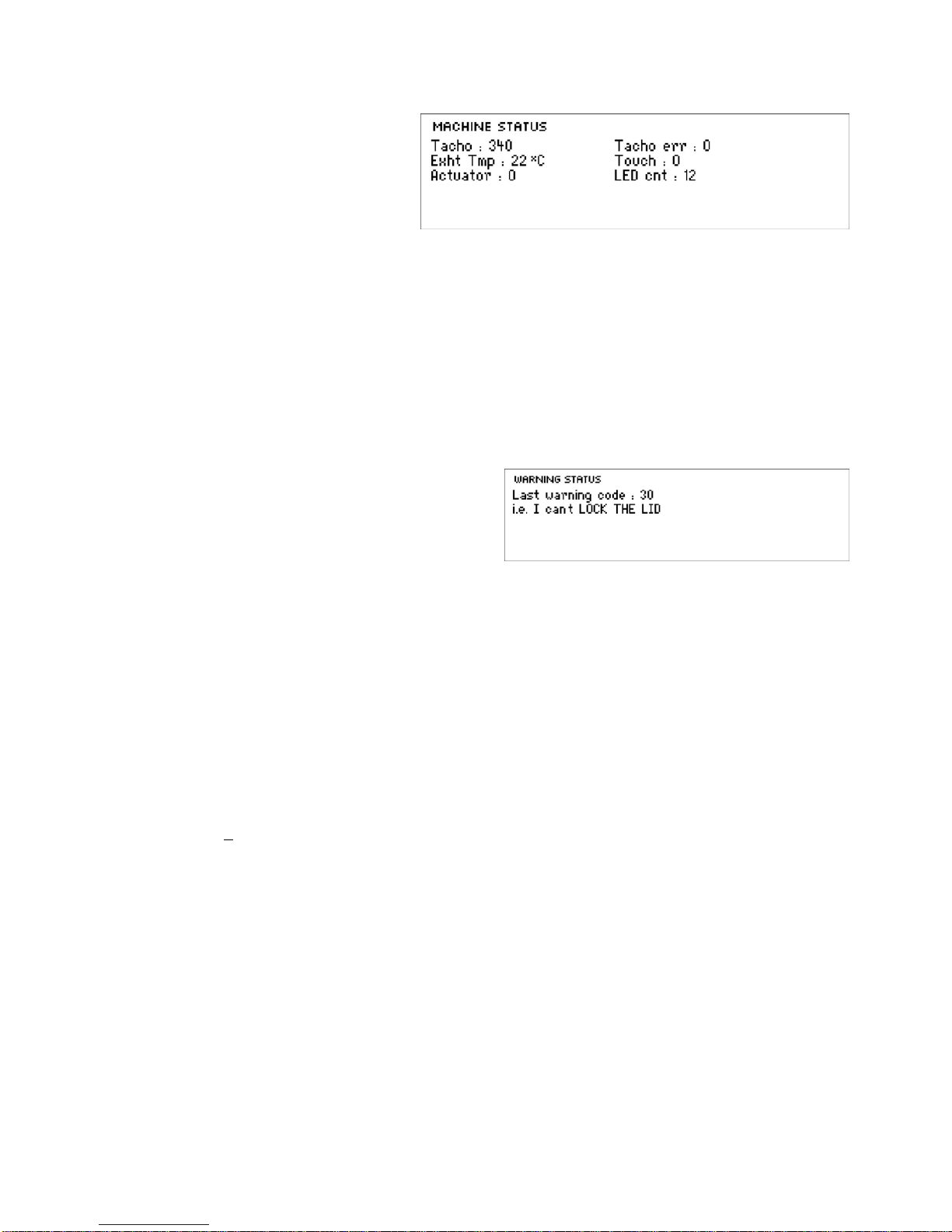
7.2.2 Machine Status Screen
Machine Status Screen
Tacho: This displays the
position of the drum. The displayed
figure is updated every five seconds
and will change as the drum
revolves.
Exht tmp: This displays the temperature in oC of the exhaust sensor.
Actuator: This displays the count of the current draw of the actuator motor.
Tacho Err: During reversals of the drum there will often be a transient error because of uncertainty
of direction during the reversing process, but this should be corrected on the next
revolution.
Touch: This displays the impedance of the conductivity contacts (refer to Section
7.3).
LED Cnt: This is a measure of the infra-red light intensity required to sense the drum position. It
is normally about 14 but can range from 5 to 53.
7.2.3 Warning Status Screen
The last User Warning will be displayed on this
screen and will be displayed until another User
Warning overwrites it or the power is switched
off.
7.3 Testing the Conductivity Contacts
Impedance Testing
It is possible to check the integrity of the conductivity contacts through diagnostics. Firstly enter
the Machine Status Screen as described in Section
7.2.2, and when in this mode, by touching
damp clothes or fingers across the conductivity contacts, the value adjacent to the word Touch will
increase. The minimum value is zero. This indicates an open circuit. The maximum value is 255.
No change in this value when touching the contacts, or conversely a high value when not touching
the contacts, would indicate a fault in this circuit.
Resistance Test
An alternative, but slightly less reliable, method of testing the conductivity contacts is to test the
circuit with a multimeter. When using this method, the power to the dryer must be switched off.
Place one probe of the multimeter on each conductivity contact. The resistance should be
6.4Mohms +
2%.
7.4 Data Download Mode
Encoded data is transmitted out of the white Wrinkle Free LED, and can be captured by an optical
download pen attached to a PC or hand held palm PC, where “Smart Tool” software interprets the
data to aid servicing.
1. Enter diagnostic mode as described in Section
7.1.
2. Push the START/PAUSE button and the Wrinkle Free LED will flash. The machine is now
in data download mode.
To exit from the data download mode, press the POWER button.
Page 18
517760C
18
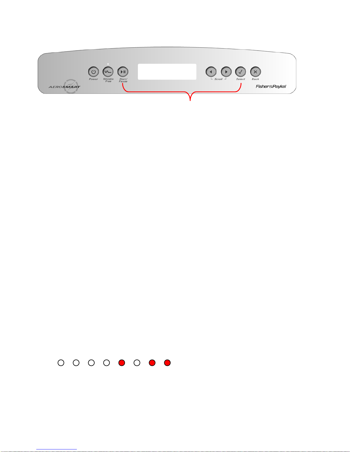
7.5 Showroom Mode
Showroom mode will play the introduction and repeat it continuously, until the dryer has been
isolated from the power supply.
To access the showroom mode follow the steps below.
1. Turn the power supply to the dryer on.
2. During the introduction sequence on the LCD display (which lasts for approx. 1 minute)
press and hold the START/PAUSE button, then press the SELECT butt on and hold these
buttons for at least two seconds.
To exit, turn off the power supply to the dryer at the wall.
8 DIAGNOSTIC MODE – LED MODELS
8.1 Entering the Diagnostic Mode
To enter the Diagnostic Mode, turn the power on at the power point and off at the console.
1. Press and hold the WRINKLE FREE button, then press the POWER button until the
machine beeps and all eight LEDs across the top of the machine illuminate. The dryer is
now in Diagnostic Mode.
2. Press the TIME DRY button three times to read the last fault.
The fault code is displayed in the row of eight cycle LEDs using a binary code. Each LED has a
value as follows:
LED VALUE
Regular = 128
Heavy = 64
Delicate = 32
Sheets = 16
Air Dry = 8
Bulky = 4
Easy Iron = 2
Wrinkle Free = 1
The fault code is determined by adding up the value of the illuminated LEDs.
For Example:
128 64 32 16 8 4 2 1
In this example, the LEDs with value “8” “2” and “1” are on.
Therefore 8+2+1=11. Fault code 11 is displayed.
Investigate corrective action in sequence as listed in the fault code summary in Section
6.3.
To exit the diagnostic mode, press the POWER button.
Press and Hold START/PAUSE, then press the SELECT button
Page 19

517760C
19
8.2 Testing the Conductivity Contacts
Impedance Test
To enter the conductivity impedance test mode, enter the diagnostic mode then press the TIME
DRY button five times. In this mode, touching damp clothes or fingers across the conductivity
contacts will cause the LED display to change. If the contacts, or harness to them, have gone
open circuit, no change will occur in the LED display. This is a useful method of checking the
integrity of the sensor cells. To exit the diagnostic mode, press the POWER button.
Resistance Test
An alternative, but slightly less reliable, method of testing the conductivity contacts is to test the
circuit with a multimeter. When using this method, the power to the dryer must be switched off.
Place one probe of the multimeter on each conductivity contact. The resistance should be
6.4Mohms +
2%.
8.3 Show Room Mode
To enter Show room mode, ensure the dryer is on at the power supply but off at the console. Push
and hold the DRYNESS LEVEL button, then press the POWER button.
To exit show room mode, disconnect the machine from the power supply.
8.4 Data Download Mode
Encoded data is transmitted out of the Lid Lock LED, and can be captured by an optical download
pen attached to a PC or hand held palm PC, where “Smart Tool” software interprets the data to aid
servicing. To enter the data down load mode.
1. Enter diagnostic mode as described in Section
8.1.
2. Push the START/PAUSE button and the Lid Lock LED will flash. The machine is now in
down load mode
To exit the Data Download mode, press the POWER button.
9 AUTOSENSING
When wet or damp clothes are loaded into a dryer they are partially saturated with water, which is
a relatively good conductor of electricity. In the AeroSmart™ dryer, sensor bars (located beneath
the lint bucket) are used to measure the conductivity. When moisture in the clothes touches
across the sensor bars, their conductivity is measured. As the clothes dry they become less
conductive and it is this measurement that is used to calculate the dryness of the clothes load.
Large loads will brush against these sensor bars more frequently than small loads, and this strike
count is used to help determine the dryness of different sized loads.
Different fabrics retain moisture differently. A thick towel containing a lot of moisture will often
conduct the same as a light synthetic garment containing very little. It is this difference in fabric
characteristics plus the initial unknown moisture content that makes the calculation of dryness
reasonably complex. To test the sensor bars, refer to Section
7.3 (LCD models) or Section 8.2
(LED models).
10 TEMPERATURE CONTROL
Autosensing is automatically selected when the AeroSmart™ dryer is turned on. The user can
select a time dry option of 20, 40 or 80 minutes through the Options menu. Autosensing of the
clothes load dryness level is achieved by touch sensors that sense the moisture content of the
load. An exhaust temperature sensor is used to monitor the exhaust temperature. The controller
limits the temperature to what is required for the various cycles and determines what elements are
used.
Page 20

517760C
20
11 COOL DOWN
The dryer enters a cool down period at the end of the cycle. During this period the dryer continues
to run with the heating elements/burner turned off, blowing ambient air through the load to help
prevent creasing.
Autosensing: If any AutoSensing cycle has been selected, the cool down period will continue until
the exhaust temperature drops to 95
o
F (35oC). However, if this temperature is not achieved after
10 minutes, the cycle will stop. This would occur if the ambient temperature was above 95
o
F
(35
o
C).
Timed Dry: If an 80 minute or 40 minute Timed Dry cycle has been selected, the cool down period
will run for the last 10 minutes of that cycle. If a 20 minutes Timed Dry cycle has been selected,
the cool down period will run for the last 5 minutes.
Cycle Cool Down
Autosensing Cool down will last until the exhaust temperature drops to 95
o
F (35oC)
or 10 minutes, whichever occurs first.
Timed Dry 80 Minutes 10 Minutes
Timed Dry 40 Minutes 10 Minutes
Timed Dry 20 Minutes 5 Minutes
Page 21
517760C
21
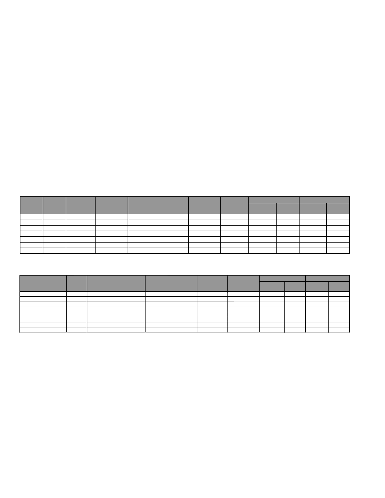
12 CYCLE CHARTS – LCD MODELS
12.1 Electric
This chart lists the available cycles that can be selected on the electric models, and provides information regarding these cycles.
Main Cycles
Bulky Cycles
Bulky Cycles.
Cycle Heat Temperature
A
utosensing/
Cooldown
1
Dryness Level
A
dditional
Timed Dry
1
commen ts 3.6kW (2/3) 1.4kW
(1/3)
3.6kW (2/3) 1.4kW
(1/3)
Comforter -Synthetic No Heat
A
mbient 80 Minutes 10 Minutes - - Off Off Off O ff
Pillows -Feather Low 127°F (53°C) 40 Minutes 10 Minutes - - On Off Off On
Pillows -Syntheti c No Heat
A
mbient 80 Minutes 10 Minutes - - Off Off Off O ff
Blanket Low 127°F (53°C) 40 Minutes 10 Minutes - - O n Off Off On
Throw Low 127°F (53°C) 40 Minutes 10 Minutes - - On Off Off On
Jacket Low 127°F (53°C) 40 Mi nutes 10 Minutes - - On Off Off On
Sleeping Bag -Feather Low 127°F (53°C)
A
utosensing 95°F (35°C) or 10 Mins Damp/Dry - On Off Off On
Sleeping Bag -Synthetic Low 127°F (53°C)
A
utosensing 95°F (35°C) or 10 Mins Damp/Dry - On Off Off On
Door Closed Direction
Door open Direction
2
1. Refer Section 11
Cycle Heat Temperature
Autosensing/
Cooldown
1
Dryness Level
Additional
Timed Dry
1
comments 3.6kW (2/3) 1.4kW
(
1/3
)
3.6kW (2/3) 1.4kW
(
1/3
)
Regular High 149°F (65°C) Autosensing 95°F (35°C) or 10 Mins Dry - On On Off On
Heavy High 149°F (65°C) Autosensing 95°F (35°C) or 10 Mins Dry/Extra dry - On On Off On
Delicate Low 127°F (53°C) Autosensing 95°F (35°C) or 10 Mins Dry Wrinkle Free On Off Off On
Sheets High 149°F (65°C) Autosensing 95°F (35°C) or 10 Mins Dry/Extra dry Wrinkle Free On On Off On
Air Dry No Heat Ambient 40 Minutes Nil - - Off Off Off Off
Bulky Low 127°F (53°C) Autosensing 95°F (35°C) or 10 Mins Dry Wrinkle Free On Off Off On
Easy Iron Medium 140°F (60°C) Autosensing 95°F (35°C) or 10 Mins Dry Wrinkle Free On Off Off On
Door Closed Direction
Door open Direction
2
Page 22
517760C
22
Life Cycles
Heat Temperature
Autosensing/
Cooldown
1
Dryness Level
Additional
Special Care
Timed Dry
1
comments 3.6kW (2/3) 1.4kW
(1/3)
3.6kW (2/3) 1.4kW
(1/3)
Handwash Low 127°F (53°C) Autosensing 95°F (35°C) or 10 Mins Dry Wrinkle Free On Off Off On
Jeans (Work & Fashion) High 149°F (65°C) Autosensing 95°F (35°C) or 10 Mins Dry Wrinkle Free On On Off On
Freshen Up No Heat Ambient 20 Minutes Nil - - Off Off Off Off
Warm Up Medium 140°F (60°C) 20 M inutes 5 Minutes - - On Off Off On
Dry Clean Med ium 140° F (60°C) 40 Minutes 10 Minutes - Wrinkle Free On Off Off On
Family
Comforter -Feather Low 127°F (53°C) Autosensing 95°F (35°C) or 10 Mins Dry/Extr a dry - O n Off Off On
Comforter -Synthetic No Heat Ambi ent 80 Minutes 10 Minutes - - Off Off Off Off
Pillo ws -F ea ther Low 127°F (53°C) 40 Minutes 10 Minutes - - On Off Off On
Pillows -Synthetic No Heat Ambient 80 Minutes 10 Minutes - - Off Off Off Off
Allergy High 149°F (65°C) Autosensing 95° F (35°C) or 10 Mins Dry/Extra dry - On On Off On
Shirts Medium 140°F (60°C) Autosensing 95°F (35°C) or 10 Mins Dry Wrinkle Free On Off Off On
Towels Hi gh 149°F (65°C) Autosensing 95°F (35°C) or 10 Mins Dry/Ext r a dry - O n O n Off On
Soft To ys Low 127°F (53°C) 20 Minu tes 5 Minutes - - On Off Off On
Sport
Sportwear Light Low 127°F (53°C) Autosensing 95°F (35°C) or 10 Mins Dry Wrinkle Free On Off Off On
Sportswear Heavy High 149°F (65°C) Autosensing 95°F (35°C) or 10 Mins Dry/ Extra dry Wrinkle Free On On Off On
Outdoor Wear No Heat Ambient 40 Mi nut es 10 Minutes - - Off Off Off Off
Protection Equip. Lo w 127° F (53°C) 40 M inutes 10 Minutes - - On Off Off On
Door Closed Direction
Door open Direction
2
1. Refer Section 11
Page 23
517760C
23
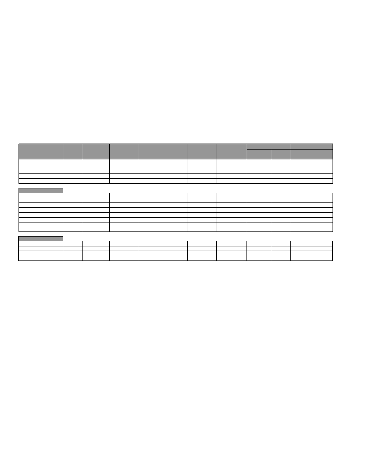
12.2 Gas
This chart lists the available cycles that can be selected on the gas models, and provides information regarding these cycles.
Main Cycles
Bulky Cycles.
Cycle Heat Temperature
Autosensing/
Cooldown
1
Dryness Level
Additional
Timed Dry
1
comments Ignition
Delay
Gas
Heating
Comforter -Synthetic No Heat Ambi ent 80 Minutes 10 Minutes - - No Heat No Heat
Pillo ws -Fea ther Low 127°F (53°C) 40 M inutes 10 Minutes - -
30s
2m 20s
Pillows -Synthetic No Heat Ambient 80 Minutes 10 Minutes - - No Heat No Heat
Blanket Lo w 127°F (53°C) 40 Minutes 10 Minutes - -
30s
2m 20s
Throw Low 127°F (53°C) 40 Minutes 10 Minutes - -
30s
2m 20s
Jacket Lo w 127°F (53°C) 40 Minutes 10 Minutes - -
30s
2m 20s
Sleeping Bag -Feather Low 127° F (53°C) Autosensing 95°F (35°C) or 10 Mins Damp/Dry -
30s
2m 20s
Sleeping B a g -Synthetic Low 127°F (53°C) Autosensing 95°F (35°C) or 10 Mins Damp/Dry -
30s
2m 20s
Door Closed Direction
Door open Direction
2
No Heat
No Heat
No Heat
No Heat
No Heat
No Heat
No Heat
No Heat
1. Refer Section 11
Cycle Heat Temperature
Autosensing/
Cooldown
1
Dryness Level
Additional
Timed Dry
1
comments Ignition
Dela
y
Gas
Heatin
g
Regular High 149°F (65°C) Autosensing 95°F (35°C) or 10 Mins Dry -
30s
3m 30s
Heavy High 149°F (65°C) Autosensing 95°F (35°C) or 10 Mins Dry/Extra dry -
30s
3m 30s
Delicate Low 127°F (53°C) Autosensing 95°F (35°C) or 10 Mins Dry Wrinkle Free
30s
2m 20s
Sheets High 149°F (65°C) Autosensing 95°F (35°C) or 10 Mins Dry/Extra dry Wrinkle Free
30s
3m 30s
Air Dry No Heat Ambient 40 Minutes Nil - - No Heat No Heat
Bulky Low 149°F (65°C) Autosensing 95°F (35°C) or 10 Mins Dry Wrinkle Free
30s
2m 20s
Easy Iron Medium 140°F (60°C) Autosensing 95°F (35°C) or 10 Mins Dry Wrinkle Free
30s
2m 20s
No Heat
No Heat
No Heat
No Heat
No Heat
No Heat
No Heat
Door Closed Direction
Door open Direction
2
Page 24
517760C
24
Life Cycles
Heat Temperature
Autosensing/
Cooldown
1
Dryness Level
Additional
Special Care
Timed Dry
1
comments Ignition
Delay
Gas
Heating
Handwash Low 127°F (53°C) Autosensing 95°F (35°C) or 10 Mins Dry Wrinkle Free
30s
2m 20s
Jeans (Work & Fashion) High 149°F (65°C) Autosensing 95°F (35°C) or 10 Mins Dry Wrinkle Free
30s
3m 30s
Freshen Up No Heat Ambient 20 Minutes Nil - - No Heat No Heat
Warm Up Medium 140°F (60°C) 20 M inutes 5 Minutes - -
30s
2m 20s
Dry Clean Med ium 140° F (60°C) 40 Minutes 10 Minutes - Wrinkle Free
30s
2m 20s
Family
Comforter -Feather Low 127°F (53°C) Autosensing 95°F (35°C) or 10 Mins Dry/Extr a dry -
30s
2m 20s
Comforter -Synthetic No Heat Ambient 80 Minutes 10 Minutes - - No Heat No Heat
Pillo ws -F ea ther Low 127°F (53°C) 40 Minutes 10 Minutes - -
30s
2m 20s
Pillows -Synthetic No Heat Ambient 80 Minutes 10 Minutes - - No Heat No Heat
Allergy High 149°F (65°C) Autosensing 95° F (35°C) or 10 Mins Dry/Extra dry -
30s
3m 30s
Shirts Medium 140°F (60°C) Autosensing 95°F (35°C) or 10 Mins Dry Wrinkle Free
30s
2m 20s
Towels Hi gh 149°F (65°C) Autosensing 95°F (35°C) or 10 Mins Dry/Ext r a dry -
30s
3m 30s
Soft To ys Low 127°F (53°C) 20 Minu tes 5 Minutes - -
30s
2m 20s
Sport
Sportwear Light Low 127°F (53°C) Autosensing 95°F (35°C) or 10 Mins Dry Wrinkle Free
30s
2m 20s
Sportswear Heavy High 149°F (65°C) Autosensing 95°F (35°C) or 10 Mins Dry/ Extra dry Wrinkle Free
30s
3m 30s
Outdoor Wear No Heat Ambient 40 Minutes 10 Minut es - - No Heat No Heat
Protection Equip. Lo w 127° F (53°C) 40 M inutes 10 Minutes - -
30s
2m 20s
Door Closed Direction
Door open Direction
2
No Heat
No Heat
No Heat
No Heat
No Heat
No Heat
No Heat
No Heat
No Heat
No Heat
No Heat
No Heat
No Heat
No Heat
No Heat
No Heat
No Heat
1. Refer Section 11
Page 25
517760C
25
Cycle Heat Temperature
Autosensing/
Cooldown
1
Dryness Level
Additional
Timed Dry
1
comments 3.6kW (2/3) 1.4kW
(
1/3
)
3.6kW (2/3) 1.4kW
(
1/3
)
Regular High 149°F (65°C) Autosensing 95°F (35°C) or 10 Mins Dry - On On Off On
Heavy High 149°F (65°C) Autosensing 95°F (35°C) or 10 Mins Dry/Extra dry - On On Off On
Delicate Low 127°F (53°C) Autosensing 95°F (35°C) or 10 Mins Dry Wrinkle Free On Off Off On
Sheets High 149°F (65°C) Autosensing 95°F (35°C) or 10 Mins Dry/Extra dry Wrinkle Free On On Off On
Air Dry No Heat Ambient 40 Minutes Nil - - Off Off Off Off
Bulky Low 127°F (53°C) Autosensing 95°F (35°C) or 10 Mins Dry Wrinkle Free On Off Off On
Easy Iron Medium 140°F (60°C) Autosensing 95°F (35°C) or 10 Mins Dry Wrinkle Free On Off Off On
Door Closed Direction
Door open Direction
2
Cycle Heat Temperature
Autosensing/
Cooldown
1
Dryness Level
Additional
Timed Dry
1
comments Ignition
Dela
y
Gas
Heatin
g
Regular High 149°F (65°C) Autosensing 95°F (35°C) or 10 Mins Dry -
30s
3m 30s
Heavy High 149°F (65°C) Autosensing 95°F (35°C) or 10 Mins Dry/Extra dry -
30s
3m 30s
Delicate Low 127°F (53°C) Autosensing 95°F (35°C) or 10 Mins Dry Wrinkle Free
30s
2m 20s
Sheets High 149°F (65°C) Autosensing 95°F (35°C) or 10 Mins Dry/Extra dry Wrinkle Free
30s
3m 30s
Air Dry No Heat Ambient 40 Minutes Nil - - No Heat No Heat
Bulky Low 149°F (65°C) Autosensing 95°F (35°C) or 10 Mins Dry Wrinkle Free
30s
2m 20s
Easy Iron Medium 140°F (60°C) Autosensing 95°F (35°C) or 10 Mins Dry Wrinkle Free
30s
2m 20s
No Heat
No Heat
No Heat
No Heat
No Heat
No Heat
No Heat
Door Closed Direction
Door open Direction
2
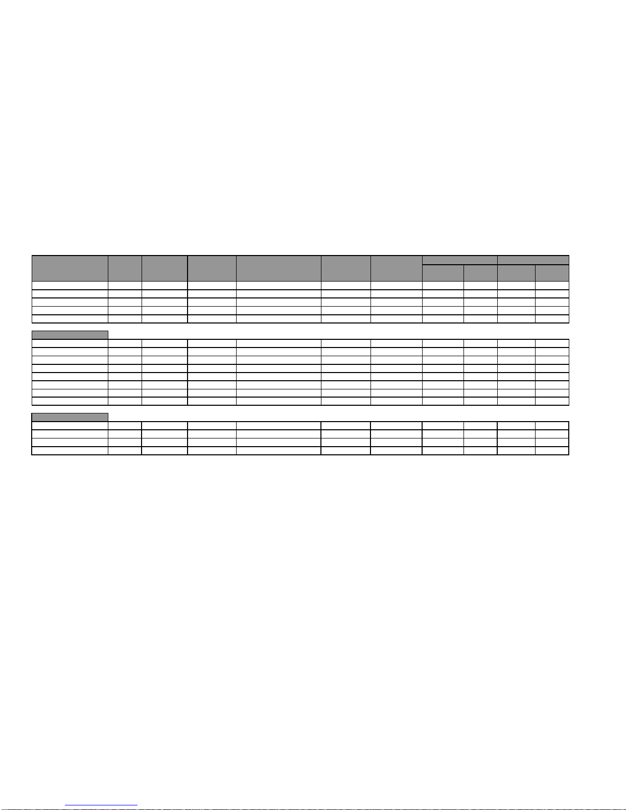
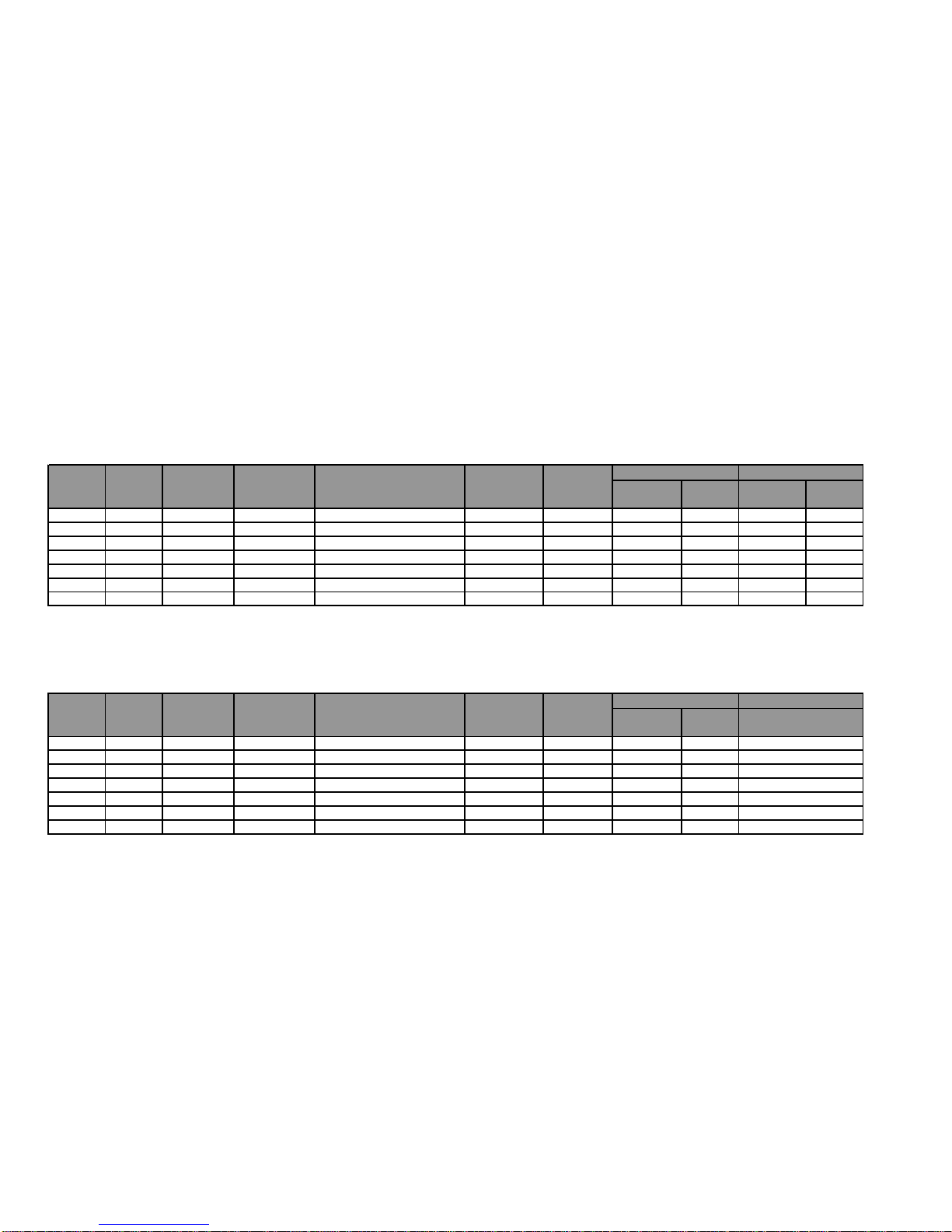
13 CYCLE CHARTS – LED MODELS
13.1 Electric
This chart lists the available cycles that can be selected on the electric models, and provides information regarding these cycles.
Main Cycles
1. Refer Section 11
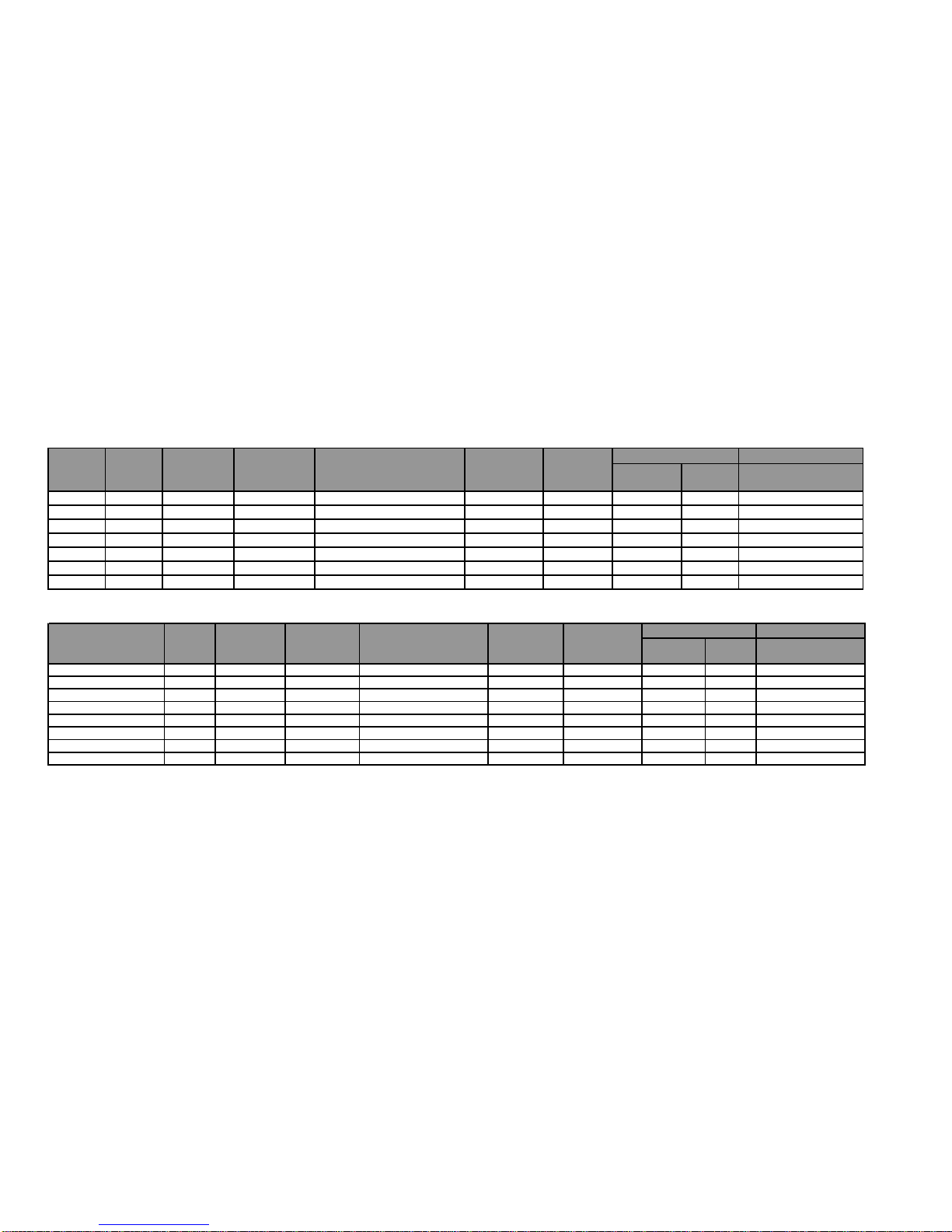
13.2 Gas
This chart lists the available cycles that can be selected on the gas models, and provides information regarding these cycles.
Main Cycles
1. Refer Section 11
Page 26
517760C
26
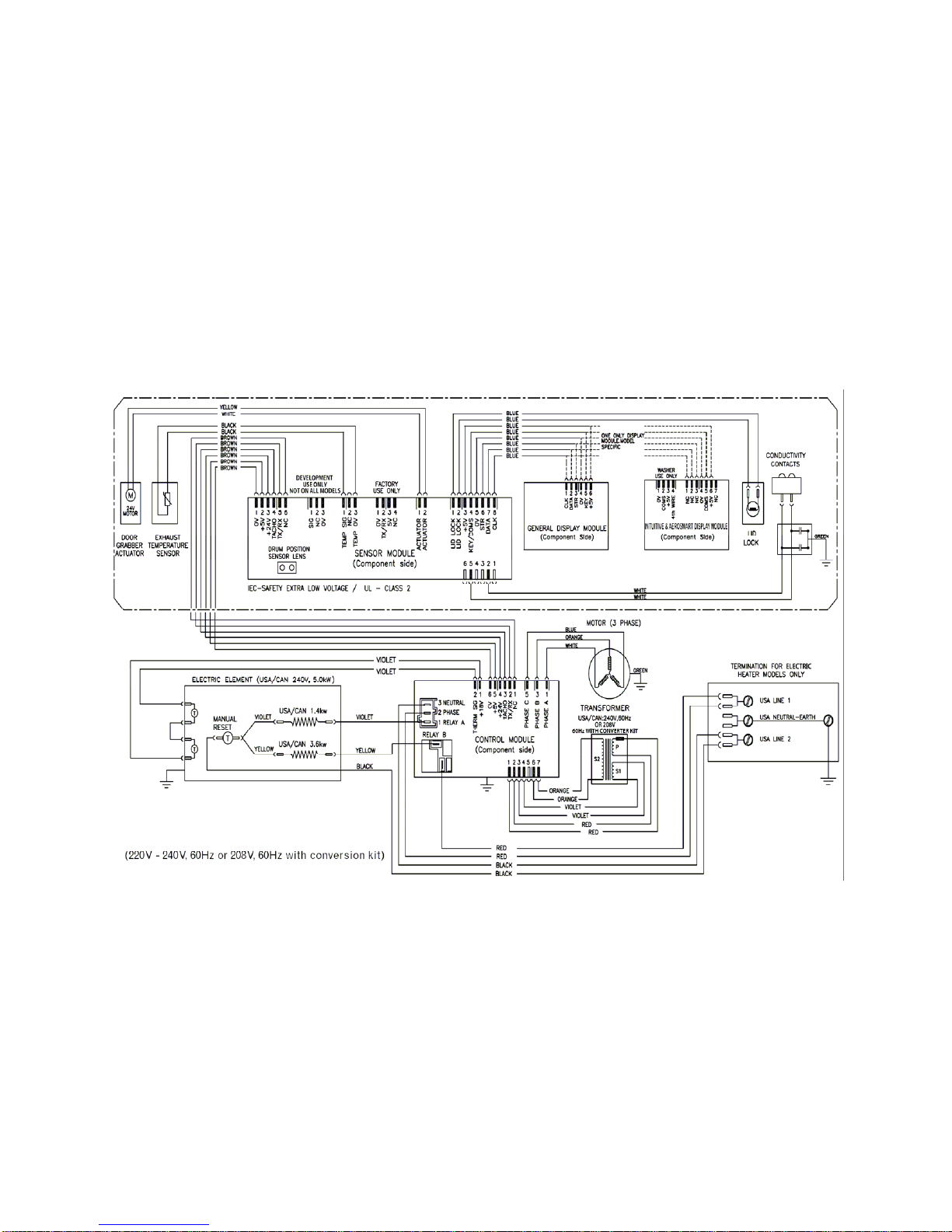
14 WIRING DIAGRAM – ELECTRIC MODELS
ELECTRIC MODELS
Page 27
517760C
27
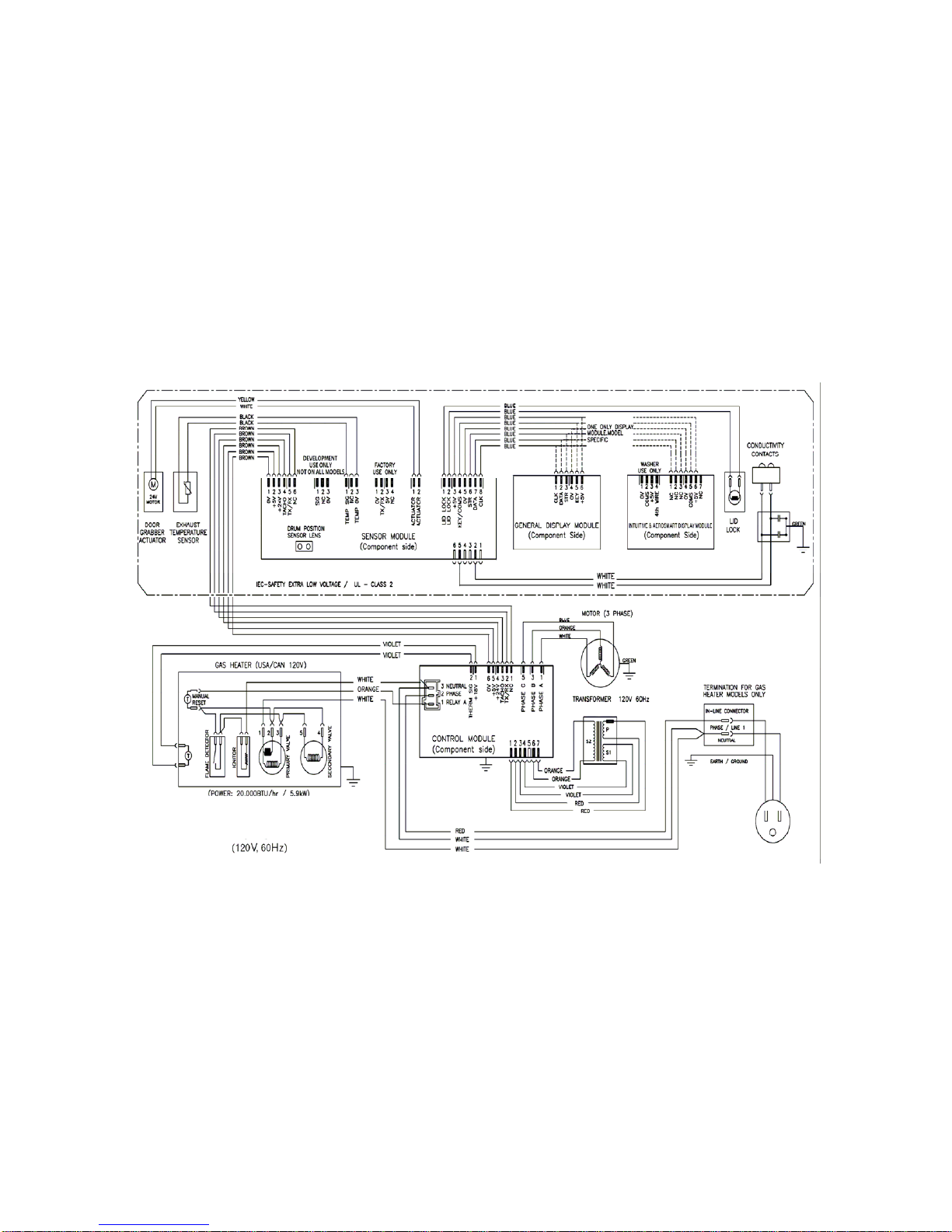
15 WIRING DIAGRAM – GAS MODELS
GAS MODELS
Page 28

517760C
28
Page 29

517760C
29
Notes
 Loading...