

Fisher & Paykel AeroSmart DE62T27CW1, AeroSmart DG62T27CW1, AeroSmart DE62T27DW1, AeroSmart DG62T27DW1 Servlce Manual
517760C
Models
DE62T27CW1
DG62T27CW1
DE62T27DW1
DG62T27DW1
Supplementary to 517760B

517760C
2

517760C - APRIL 2007 REPRINT - AUGUST 2007
Fisher & Paykel Appliances Inc
5800 Skylab Road
Huntington Beach
CA 92647
USA
Phone: 1 888 936 7872
3
The specifications and servicing procedures outlined in this manual are subject to change without
notice.
The latest version is indicated by the reprint date and replaces any earlier editions.
Note: This supplementary manual is only to be used in conjunction with service manual
517760B. It is not intended to be used on its own.

517760C
4
CONTENTS
1 SERVICING REQUIREMENTS................................................................................................5
1.1 Health & Safety...............................................................................................................5
1.2 Electrical Safety ..............................................................................................................5
1.3 Electrostatic Discharge ...................................................................................................5
1.4 Good Working Practices .................................................................................................5
1.5 Safety Test......................................................................................................................5
1.6 Sheet Metal Edges..........................................................................................................5
2 MODELS INFORMATION........................................................................................................6
2.1 Models Number...............................................................................................................6
2.2 Serial Number.................................................................................................................6
2.3 Product Code..................................................................................................................7
3 TECHNICAL OVERVIEW ........................................................................................................7
3.1 Finish ..............................................................................................................................7
3.2 Electrical Supply..............................................................................................................7
3.3 Dimensions .....................................................................................................................7
3.4 Maximum Capacity (Full Load) .......................................................................................7
4 COMPONENTS........................................................................................................................8
4.1 Control Panel Assembly..................................................................................................8
4.2 Fascia .............................................................................................................................9
5 SERVICE PROCEDURES.....................................................................................................10
5.1 Removal of Lid..............................................................................................................10
5.2 Removal of Console......................................................................................................10
5.3 Removal of Display Module ..........................................................................................10
6 DIAGNOSTICS ......................................................................................................................11
6.1 Overview – LCD Models ...............................................................................................11
6.2 Overview – LED Models................................................................................................11
6.3 Fault Code Summary....................................................................................................12
7 DIAGNOSTIC MODE – LCD MODELS .................................................................................16
7.1 Entering the Diagnostic Mode.......................................................................................16
7.2 Service Screen..............................................................................................................16
7.2.1 Fault Status Screen..............................................................................................16
7.2.2 Machine Status Screen........................................................................................17
7.2.3 Warning Status Screen........................................................................................17
7.3 Testing the Conductivity Contacts.................................................................................17
7.4 Data Download Mode....................................................................................................17
7.5 Showroom Mode...........................................................................................................18
8 DIAGNOSTIC MODE – LED MODELS .................................................................................18
8.1 Entering the Diagnostic Mode.......................................................................................18
8.2 Testing the Conductivity Contacts.................................................................................19
8.3 Show Room Mode ........................................................................................................19
8.4 Data Download Mode....................................................................................................19
9 AUTOSENSING.....................................................................................................................19
10 TEMPERATURE CONTROL .................................................................................................19
11 COOL DOWN.........................................................................................................................20
12 CYCLE CHARTS – LCD MODELS .......................................................................................21
12.1 Electric.....................................................................................................................21
12.2 Gas ..........................................................................................................................23
13 CYCLE CHARTS – LED MODELS........................................................................................25
13.1 Electric.....................................................................................................................25
13.2 Gas ..........................................................................................................................25
14 WIRING DIAGRAM – ELECTRIC MODELS .........................................................................26
15 WIRING DIAGRAM – GAS MODELS....................................................................................27

517760C
5
1 SERVICING REQUIREMENTS
1.1 Health & Safety
Note: When servicing the AeroSmartTM electronic dryer, health and safety issues must be
considered at all times. Specific safety issues are listed below to remind service people of
the health and safety issues.
1.2 Electrical Safety
WARNING! TO AVOID ELECTRIC SHOCK!
Do not attempt to service this dryer without suitable training and qualifications.
Ensure the mains power has been disconnected before servicing any part of the dryer. If the
power is required to be on for electrical fault finding, or checking the operation, then extreme care
should be taken not to make contact with electrical components other than with testing probes.
Ensure the dryer is turned off when removing any electrical component or connection.
1.3 Electrostatic Discharge
Electronic components are prone to damage from electrostatic discharges. The electronic
modules in this product contain no user serviceable components and breaking seals to access
internal components of an electronic module may void the product warranty. Avoid contact with
PCB edge connectors when handling electronic modules.
1.4 Good Working Practices
Ensure the work areas are kept tidy and free of hazards while servicing the dryer. On completion
of the servicing, ensure the dryer and work areas are left clean and tidy.
1.5 Safety Test
On completion of any service carried out to the dryer, all safety tests as required by law must be
carried out.
1.6 Sheet Metal Edges
When working around cut sheet metal edges use appropriate gloves or protection to eliminate the
chance of receiving a laceration.
517760C
6
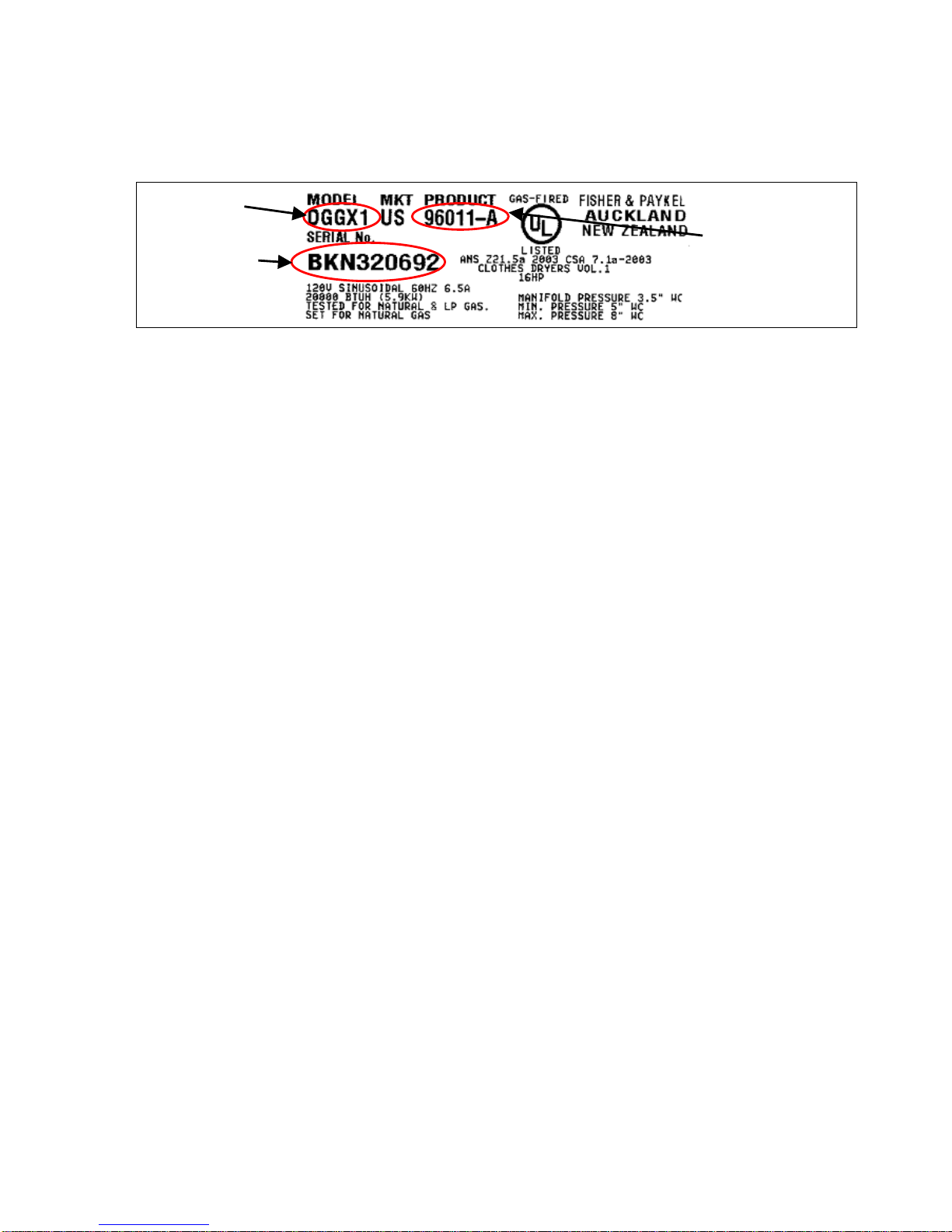
2 MODELS INFORMATION
The product serial plate is located on the upper rear of the cabinet and contains the following
information:
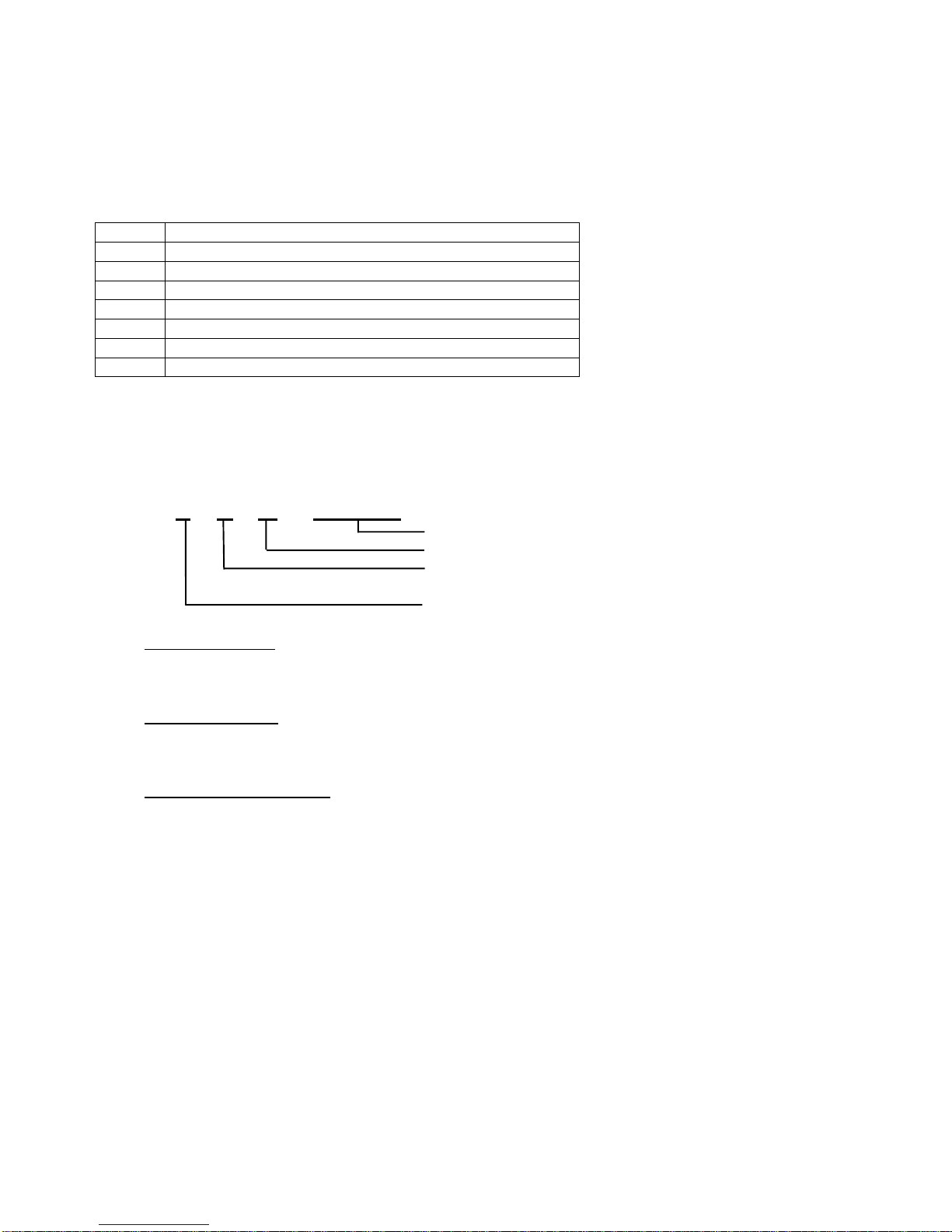
2.1 Models Number
The models number contains the following information:
D
Product Type (Dryer)
E
Heating Type (E = Electric / G = Gas)
62
Capacity cu/ft (6.2) IEC
T
Top Loading
27
Size (27 inches wide)
C
Console (C = LCD / D = LED)
W
Color (White)
1
Series (1)
2.2 Serial Number
The serial number consists of three letters and six digits and contains the following information:
Example:
L F U 123456
Sequential Serial Number
Manufacturing Plant Code
FISHERPAYKUL Code indicates month of
manufacture
CUMBERLAND Code indicates year of manufacture
Cumberland Code
Letter C U M B E R L A N D
Year 1 2 3 4 5 6 7 8 9 0
Fisherpaykul Code
Letter F I S H E R P A Y K U L
Month 1 2 3 4 5 6 7 8 9 10 11 12
Manufacturing Plant Code
F Refrigeration – New Zealand
M Range & Dishwasher
N Laundry – New Zealand
Q Refrigeration – Australia
U Laundry – U.S.A.
In the example above, the appliance was manufactured in the first month of the seventh year
(2007) at the Laundry plant in Ohio (U.S.A.).
517760C
7
2.3 Product Code
A suffix letter has been added to the Product Code. This suffix letter will change whenever a part
is changed that is not completely retro-fittable without the need for a kit, or whenever a cosmetic
change is made.
At the same time, separate parts manuals will be produced for each product code, making it easier
for the service technician to obtain the correct part for the appliance they are servicing. The part
number of the manual will be the same as the Product Code.
It is now important that the service technician obtains the Product Code from the serial plate of the
appliance before ordering parts, then refers to the appropriate parts manual to ensure that the
correct part numbers are obtained.
3 TECHNICAL OVERVIEW
3.1 Finish
Cabinet: Pre-paint (Polyester)
Touch-Up Paint: White #503086
Lid: ABS Co-injected, one piece
Console: ABS plastic
Facia (LCD Models): IMD (In-mould decorative) Polycarbonate/PET
Facia (LED Models): PC/PBT Printed film + clear ABS.
Drum: Stainless steel grade 430T
Top Deck: Polypropylene
3.2 Electrical Supply
Operating Voltage Maximum Current
USA Electric 220/240V AC 60Hz 24 Amps
USA Gas 110/120V AC 60Hz 6 Amps
3.3 Dimensions
Height to lid
Open 55 ½ in – 56 ¾ in 1410mm – 1440mm
Closed 36 ½ in – 37 ½ in 925mm – 955mm
Height to console 40 ¼ in – 41 ½ in 1020mm – 1050mm
Width 27 685mm
Depth 27 ½ in 700mm
Note: Exact height of the AeroSmart
TM
dryer is dependent on how far the feet are inserted
into the base of the dryer.
Weight Packed 152lbs (69kg)
Unpacked 134 lbs (61kg)
3.4 Maximum Capacity (Full Load)
Drum Volume 6.2 cubic feet (.184 cubic meters)
Model
Serial
517760C
8
4 COMPONENTS
The only visual change of major components between the G (General), I (Intuitive™) and the
AeroSmart™ dryer is with the console assembly.
The Aerosmart™ LCD models incorporates an IMD (In-mould decorative display), which uses
capacitive touch buttons that sense the user’s fingers over the buttons. It has a large LCD Display
allowing us to show graphics on the screen. The new screen allows us to present information
simply while providing a lot more detail, such as graphic icons, pop up explanations and
confirmation.
The AeroSmart™ LED models incorporates backlit buttons, with the selected button illuminated
more brightly than the others. Words indicating selections made are also illuminated.
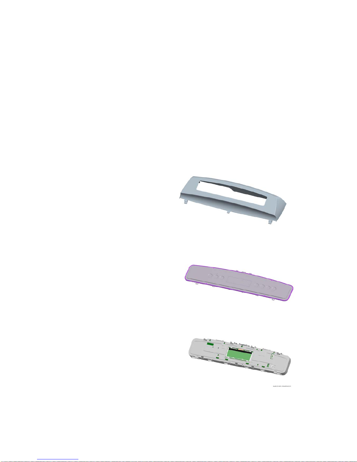
4.1 Control Panel Assembly
The three core components of the control panel assembly are the console, the fascia, and the PCB
and housing.
Console
The console, which is made from ABS is the
housing to which the fascia and PCB housing
attaches. Lugs at the base of the console
locate into the top deck. The console is secured
to the rear of the top deck by two screws.
Fascia
The fascia will be one of either the IMD fascia
for LCD models or the touch panel for LED
models.
PCB and Housing
The PCB, which contains the electronics, is
mounted within a plastic housing. The PCB
housing is clipped into the console at the
bottom, and secured with four screws along the
top.
517760C
9
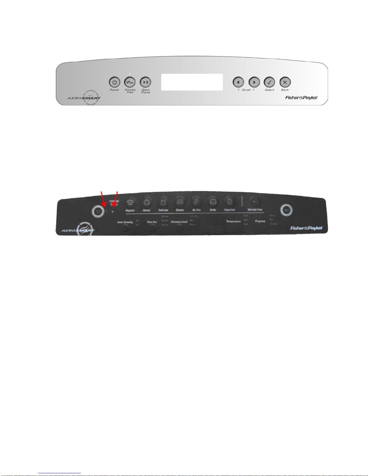
4.2 Fascia
LCD Models
1. Power On/Off button.
2. Wrinkle Free On/Off. When the LED is on the wrinkle free option is turned on.
3. Wrinkle Free LED used also for data download (Refer to Section
7.4).
4. Start/Pause button.
5. LCD Screen.
6. Left arrow (used when scrolling through options on the LCD screen).
7. Right arrow (used when scrolling through options on the LCD screen).
8. Select button – Use to confirm setting.
9. Back button – Use to cancel setting.
LED Models
1. Power button. 10. Bulky button.
2. Auto Sensing button. 11. Air Dry button.
3. Time Dry button. 12. Sheets button.
4. Dryness Level button. 13. Delicate button.
5. Temperature. 14. Heavy button.
6. Progress. 15. Regular button.
7. Start/Pause button. 16. Lid Lock icon.
8. Wrinkle Free button. 17. Service Spanner icon.
9. Easy Iron button.
1
2
5
6
7
8
9
3
4
1
2 3 4 5 6
7
15 14 13 12 11 10 9 8 17 16
 Loading...