

Page 1
INSTALLATION GUIDE
Accessory door panels
SAFETY & WARNINGS
!
WARNING!
Electric Shock Hazard
Failure to follow this advice may result in
electrical shock or death.
•
Read and follow the safety and warnings before
operating this appliance.
!
WARNING!
Cut Hazard
Failure to use caution could result in injury.
• Take care: some edges may be sharp.
●
Ensure a 2mm minimum ventilation gap below the
door is maintained.
●
Ensure all packaging is removed and disposed
of responsibly.
●
Ensure the Knock-To-Pause module is oriented
correctly before attaching.
COMPONENTS REQUIRED
Crosshead driver Pliers
1
2
3
SERIES 11 models
SERIES 7 & 9 models
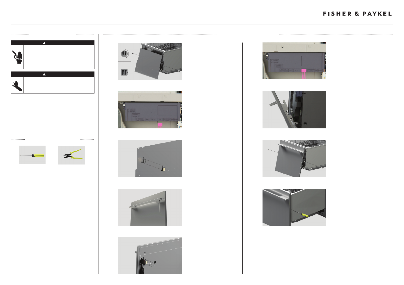
DOOR PANEL INSTALLATION
Remove both side pins with
pliers and carefully pull the panel
bracket down and out slightly.
Unplug knock-to-pause module
from the controller and remove
the earth wire from the bracket.
Remove the Knock-to-Pause
module from the back of
the bracket.
6
7
8
Reconnect the Knock-to-Pause
module to the UI 1 slot on the
wash controller as shown.
Reconnect the Earth wire to the
panel bracket.
Warning: Failure to reconnect the
Earth wire may result in electrical
shock or death.
Carefully fit the panels onto the
product. Re-insert both side pins
to secure panels in place.
Double models
Repeat each step on both drawers.
Ensure a 8mm minimum ventilation gap below the door
is maintained.
For more information, visit www.fisherpaykel.com
4
5
Install the handle to the panel
following the installation
guidance available for your
handle kit.
Attach the Knock-to-Pause
module to the panel as shown.
Ensure the module is correctly
oriented and is not in contact
with the brackets before securing.
9
Insert a crosshead driver into
the hole above each side pin
and rotate to adjust the panel
alignment. There is a maximum
travel distance of ± 1/16”(2mm).
Repeat for both sides if required.
431158A 10.22 US CA
 Loading...