

Page 1

OWNER’S MANUAL
Uses two AA ALKALINE batteries only.
Do not use “Heavy Duty” batteries.
Do not use ordinary Zinc Carbon batteries.
Not for Underwater Use
DO NOT SUBMERGE
Page 2

TABLE OF CONTENTS
Congratulations!
Congratulations on the purchase of your new Fisher F22™ Metal Detector. The F22 is the result of
many years of software engineering and features the latest advancements in lightweight design and
target accuracy. The F22 can be used with its default turn-on-and-go settings, or you can adjust the
detector's settings to match your hunting conditions. No longer do you need to fear the weather, the
F22 is completely weatherproof. Laugh at the rain. No longer will weather be a force that stops you
from enjoying your sport. Treasure hunting enthusiasts from around the world were involved in the
development of this revolutionary new detector. This manual has been written to help you get optimal
use of your detector so we hope you will read it thoroughly before your first outing.
Happy Hunting from Fisher Research Labs!
The F22 operates at a frequency of 7.69 kHz and comes with a 9” triangulated concentric
elliptical searchcoil. The F22 shares searchcoil compatibility with the F11and F44.
Terminology . . . . . . . . . . . . . . . . . . . . . . . . . . . . . . . . . . . . . . . . . . . . . . . . . . .3
Contents . . . . . . . . . . . . . . . . . . . . . . . . . . . . . . . . . . . . . . . . . . . . . . . . . . . . .4
Assembly . . . . . . . . . . . . . . . . . . . . . . . . . . . . . . . . . . . . . . . . . . . . . . . . . . .5-6
Batteries (use alkaline batteries) . . . . . . . . . . . . . . . . . . . . . . . . . . . . . . . . . .7
Quick-Start Demonstration . . . . . . . . . . . . . . . . . . . . . . . . . . . . . . . . . . . . . . .8
The Basics of Metal Detecting . . . . . . . . . . . . . . . . . . . . . . . . . . . . . . . . .9-10
9” Searchcoil . . . . . . . . . . . . . . . . . . . . . . . . . . . . . . . . . . . . . . . . . . . . . . . . .10
How to Work the Controls . . . . . . . . . . . . . . . . . . . . . . . . . . . . . . . . . . . . . . .11
The Display . . . . . . . . . . . . . . . . . . . . . . . . . . . . . . . . . . . . . . . . . . . . . . . . . .12
Depth Indicator . . . . . . . . . . . . . . . . . . . . . . . . . . . . . . . . . . . . . . . . . . . . . . .12
Overload Warning . . . . . . . . . . . . . . . . . . . . . . . . . . . . . . . . . . . . . . . . . . . . .12
Menu . . . . . . . . . . . . . . . . . . . . . . . . . . . . . . . . . . . . . . . . . . . . . . . . . . . . .13
Volume . . . . . . . . . . . . . . . . . . . . . . . . . . . . . . . . . . . . . . . . . . . . . . . . . . . . .13
Sensitivity . . . . . . . . . . . . . . . . . . . . . . . . . . . . . . . . . . . . . . . . . . . . . . . . . . .13
Notch . . . . . . . . . . . . . . . . . . . . . . . . . . . . . . . . . . . . . . . . . . . . . . . . . . . . .14
Modes . . . . . . . . . . . . . . . . . . . . . . . . . . . . . . . . . . . . . . . . . . . . . . . . . .14-15
Custom Mode . . . . . . . . . . . . . . . . . . . . . . . . . . . . . . . . . . . . . . . . . . . . . . . .14
Pinpoint . . . . . . . . . . . . . . . . . . . . . . . . . . . . . . . . . . . . . . . . . . . . . . . . . . . . .15
How to Pinpoint . . . . . . . . . . . . . . . . . . . . . . . . . . . . . . . . . . . . . . . . . . . . . .15
Target-ID . . . . . . . . . . . . . . . . . . . . . . . . . . . . . . . . . . . . . . . . . . . . . . . . .16-17
4-Tone Target-ID . . . . . . . . . . . . . . . . . . . . . . . . . . . . . . . . . . . . . . . . . . . . . .16
Depth and Target Display . . . . . . . . . . . . . . . . . . . . . . . . . . . . . . . . . . . .18-19
Target Groups and ID Numbers . . . . . . . . . . . . . . . . . . . . . . . . . . . . . . .18-19
Headphone Jack . . . . . . . . . . . . . . . . . . . . . . . . . . . . . . . . . . . . . . . . . . . . . .20
Characteristics and Limitations . . . . . . . . . . . . . . . . . . . . . . . . . . . . . . . . . . .21
Troubleshooting . . . . . . . . . . . . . . . . . . . . . . . . . . . . . . . . . . . . . . . . . . . . . .22
Treasure Hunter's Code of Ethics . . . . . . . . . . . . . . . . . . . . . . . . . . . . . . . .23
Warranty . . . . . . . . . . . . . . . . . . . . . . . . . . . . . . . . . . . . . . . . . . . . . . . . . . .23
Accessories . . . . . . . . . . . . . . . . . . . . . . . . . . . . . . . . . . . . . . . . . . .Back Page
2
Page 3

TERMINOLOGY
The following terms are used throughout the manual and are standard
terminology among detectorists.
RELIC
A relic is an object of interest by reason of its age or its association with
the past. Many relics are made of iron, but can also be made of bronze
or precious metals.
IRON
Iron is a common, low-grade metal that is an undesirable target in certain
metal detecting applications. Examples of undesirable iron objects are
old cans, pipes, bolts and nails. Sometimes the desired target is made
of iron. Property markers, for instance, contain iron. Valuable relics can
also be composed of iron; cannon balls, old armaments and parts of old
structures and vehicles can also be composed of iron.
FERROUS
Metals which are made of, or contain iron.
ELIMINATION
Reference to a metal being "eliminated" means the detector will not emit
a tone, nor display a Target-ID, when a metal object passes through the
searchcoil's detection field.
DISCRIMINATION
When the detector emits different tones for different types of metals, and
when the detector "eliminates" certain metals, we refer to this as the
detector "discriminating" among different types of metals.
Discrimination is an important feature of professional metal detectors.
Discrimination allows the user to ignore trash and otherwise undesirable
objects.
PINPOINTING
Pinpointing is the process of finding the exact location of a buried object.
Long-buried metals can appear exactly like the surrounding soil and can
therefore be very hard to isolate from the soil.
GROUND CANCELATION
Ground Cancelation is the ability of the detector to ignore, or "see
through," the earth's naturally occurring minerals, and only sound a tone
when a metal object is detected. This detector incorporates proprietary
circuitry to eliminate false signals from many mineralized soils.
3
Page 4
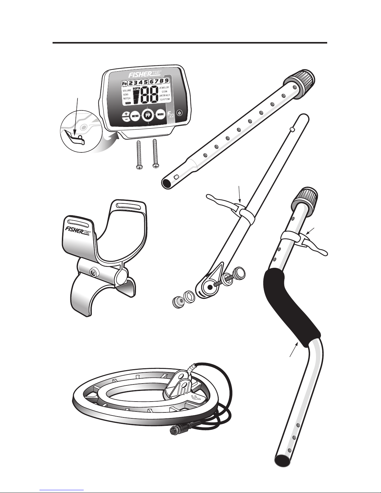
CONTENTS OF BOX
The following detector components are in the box:
H
a
n
d
g
r
i
p
V
e
l
c
r
o
V
e
l
c
r
o
4
3. Searchcoil
O-Ring
One installed on coil connector
and a replacement O-Ring included
in manual bag.
4. Middle
Stem
5. Lower Stem
with Bolt &
Knurled Knob
attachment
6. S-Rod
2. Armrest Assembly with
Screw and Lock-Nut
1. Control Housing
with 2 screws
Headphone
Jack Cover
Page 5

ASSEMBLY
Tool Required: #1 Phillips Screwdriver
●
1 • Remove the Screw from the Armrest.
• Slide the Armrest over the end
of the S-Rod.
• Attach with Screw and Lock-Nut.
●
2 Attach Control Housing with Screws;
install back screw first.
NOTE:
• The Handgrip fits under the Control
Housing.
Handgrip may partially cover one
mounting hole. Peel back
Handgrip to expose the front hole.
• Ensure the headphone jack cover
is properly seated before attaching
the control housing.
H
a
n
d
g
r
i
p
S
e
a
r
c
h
C
o
i
l
C
a
b
l
e
C
a
b
l
e
P
l
u
g
S
-
R
o
d
M
i
ddl
e
S
t
e
m
L
o
c
k
i
n
g
C
o
l
l
a
r
L
o
c
ki
n
g
C
o
l
l
a
r
H
e
a
d
p
h
o
n
e
Ja
c
k
Battery
Compartment
(back side)
A
r
m
r
e
s
t
Triangulated
Concentric
Elliptical
Waterproof
Seachcoil
*
V
e
l
c
r
o
S
t
r
a
p
V
e
l
c
r
o
St
r
a
p
O
-
R
i
n
g
K
n
u
r
l
e
d
K
n
o
b
C
o
i
l
W
a
s
h
e
r
Place Headphone
Jack Cover in
recessed pocket
so it is level with
the surface of the
housing and held
in place between
the housing
and S-Rod.
Caution:
Forcing in MIDDLE STEM with CAM LOCK raised may
form a burr on cam lock. If this happens, remove burr with
knife to allow insertion.
*
Note: Very tall users can purchase the optional
Extended Lower Stem (TUBE5X), for extended reach.
5
Page 6

6
●
3 Position S-Rod upright.
●
4 Rotate the LOCKING COLLAR fully in the counterclockwise direction.
●
5 Insert your finger inside the tube and make sure the INTERNAL CAM LOCK
is flush with the inside of the tube.
●
6
Insert the MIDDLE STEM into the S-ROD, with the SILVER BUTTON pointed
upward.
●
7 Rotate the MIDDLE STEM until the SILVER BUTTON locates in the hole.
●
8 Twist the LOCKING COLLAR fully in the clockwise direction until it locks.
●
9 Repeat this process on the LOWER STEM.
●
10 Using the BOLT and KNURLED KNOB, attach the SEARCHCOIL to the
LOWER STEM.
●
11
Adjust the LOWER STEM to a length that lets you maintain a comfortable upright
posture with your arm relaxed at your side, and the SEARCHCOIL parallel to the
ground in front of you.
●
12
Wind the CABLE securely around the STEMS, leaving slack at the bottom.
●
13
Connect CABLE PLUG to housing.
Do not twist the Cable or Plug. Turn Locking Ring only. Use minimal finger
pressure to start the threads. Do not cross-thread. When the Locking Ring is
fully engaged over the threaded connector, give it a firm turn to make sure it is
very tight. When the Locking Ring is fully engaged over the threaded connector,
it may not cover all of the threads.
ASSEMBLY
(Continued)
S-ROD
LOCKING
COLLAR
INTERNAL
CAM LOCK
SILVE R BUTTON
MIDDLE
STEM
S-ROD
MIDDLE STEM
●
4
●
5
●
6
●
6
●
7
Page 7
7
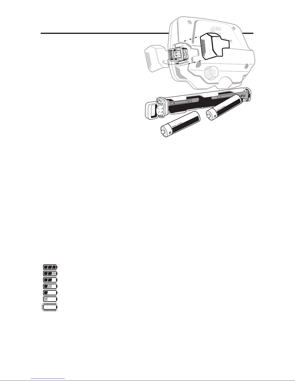
The detector requires two AA batteries.
We recommend ALKALINE batteries
(not included).
Do not use ordinary “Zinc
Carbon” batteries.
Do not use “Heavy Duty” batteries.
Rechargeable batteries can also be
used. If you use rechargeables, we
recommend using a “Nickel Metal
Hydride” rechargeable battery. The
battery compartment is located on
the right side of the Control Housing.
Both batteries should be installed with
the negative terminal down.
Remove battery tube:
1. Slide the battery door off.
2. Extend the handle on the battery tube (with your finger or by using the tab
on the battery door to pry the handle into the extended position)
3. Pull on the handle to remove (do not use the battery door tab to pull the tube
out of the control housing, as this may cause damage to the battery door)
To install battery tube:
1. Position the handle on the battery tube in the lowered position.
2. Firmly push down on the battery tube, until the battery tube handle is
flushed with the housing. (The battery tube will only insert one way, with the
brass contacts facing towards the display and the hinged side of the handle
towards the back.)
BATTERY LIFE
Expect 25 to 30 hours of life from 2 AA Alkaline batteries. Rechargeable
batteries provide about 15 hours of usage per charge. Backlight increases
power consumption and decreases battery life, with significant power drain at
maximum brightness.
BATTERY INDICATOR
The battery icon has three segments plus an outline segment. The amount of
battery voltage for two ALKALINE batteries is indicated as follows:
All segments black: >2.8 volts
Right segment grey, other two black: >2.6 volts
Right segment off, other two black: >2.4 volts
Right segment off, mid grey, left black: >2.2 volts
Right and mid segments off, left black: >2.0 volts
Right and mid segments off, left grey: >1.8 volts
All segments off, outline flashing: < 1.8 volts
It is recommended to change the batteries when you see the one black segment.
SPEAKER VOLUME AND BATTERY CHARGE
You may notice the speaker volume drop while one battery segment is
illuminated. With the outline flashing, low speaker volume will be very apparent.
BATTERY DISPOSAL & RECYCLING
Alkaline batteries may be disposed of in a normal waste receptacle or
recycled. Other battery chemistries should be recycled.
BATTERIES
Page 8
8
QUICK-START DEMONSTRATION
I. Supplies Needed
•
Nail (made of iron)• U.S. Quarter (or silver coin) • U.S. Nickel
•
Gold Ring • U.S. Dime • U.S. Penny, dated after 1982 (post-1982 pennies are made of Zinc)
(Most newer non-U.S. coinage also contains mostly Zinc)
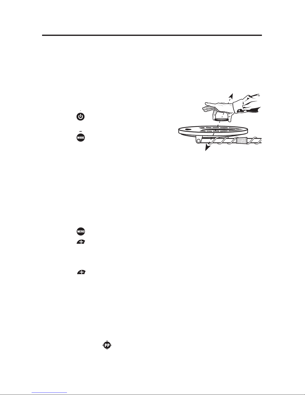
II. Position the Detector
a. Place the detector on a table with the searchcoil hanging over the edge (or,
have a friend hold the detector with the searchcoil off the ground).
b. Keep the searchcoil away from walls, floors and metal objects.
c. Remove watches, rings and jewelry.
d. Turn off lights or appliances whose electromagnetic
emissions may cause interference.
e. Pivot the searchcoil back.
f. Press to power on. A series of 10 numbers will
sequence across the screen, this is the
serial number.
g. Press twice. All target categories are
now illuminated.
III. Demonstrate Modes:
a. Press MODE button twice, display indicates Artifact Mode.
b. Pass all objects over the searchcoil and notice the different tones. Notice
the target icon indicators and the large two digit Target-ID number
displayed for each item.
Nail: low tone
Nickel: medium tone
Zinc Penny: medium tone
Gold Ring: most gold rings will register with a medium tone
Dime: high tone
Quarter: high tone
IV. Demonstrate NOTCH Feature:
a. Press until “NOTCH” is illuminated.
b. Press until target icon “3” is flashing, then wait until icon stops flashing
(approximately 5 seconds). The icon will be blanked out.
c. Pass the Nickel over the searchcoil. It will not be detected. The Nickel has
been “notched” out.
d. Press 4 times, target icon 3 is now flashing, then wait until icon stops
flashing
(approximately 5 seconds). The icon will now be notched back in.
Only one target category can be notched at a time. Repeat the process to
notch additional categories
V.
Demonstrate DEPTH Indicator:
a. Pass the Nickel close to the searchcoil (about 1” away).
b. Notice the depth bar graph indicating a shallow target.
c. Wave the Nickel farther away from the searchcoil and notice additional
bar graph segments illuminating, indicating a deeper target.
VI.
Demonstrate PINPOINT feature:
a.
Press and hold . “PP” momentarily appears on the screen.
b. Hold a coin motionless over the searchcoil.
c. Lower coin toward searchcoil and then raise coin away from searchcoil.
d. Notice the sound changes as the coin distance varies.
e. Notice the depth indicator changes as the coin moves up and down.
Page 9

9
THE BASICS OF METAL DETECTING
This metal detector is intended for locating buried metal objects. When
searching for metals, underground or on the surface, you have the following
challenges and objectives:
1. Ignoring signals caused by ground minerals.
2. Ignoring signals caused by metal objects that you do not want to find,
like nails.
3. Identifying a buried metal object before you dig it up.
4. Estimating the size and depth of objects, to facilitate digging them up.
5. Eliminating the effects of electromagnetic interference from other
electronic devices.
Your metal detector is designed with these things in mind.
1. Ground Minerals
All soils contain minerals. Signals from ground minerals can interfere with
the signals from metal objects you want to find. All soils differ and can differ
greatly in the type and amount of ground minerals present. This detector
has proprietary circuitry to automatically eliminate interfering signals from
minerals that occur naturally in the ground.
NOTE: This detector will not completely eliminate interference from all
types of minerals. For example, the detector IS NOT designed for use on
wet sand saltwater beaches. Another example of soil this detector will not
eliminate is any soil containing large concentrations of iron oxides, which
are usually red in color.
2. Trash
If searching for coins, you want to ignore items like aluminum foil and nails.
You can see the Target-ID of the buried objects, listen to the sounds and
then decide what you want to dig up. Or, you can eliminate unwanted
metals from detection by using the different Modes or NOTCH feature or
use the Custom mode to create your own discrimination settings.
3. Identifying Buried Objects
Metal objects are identified along the 9-segment Conductivity graphic symbols
and with a large 2-digit target ID number in the center of the screen. Both are
indicators of the relative electrical conductivity of different objects. Segments to
the right indicate more conductive targets. Iron objects will be illuminated with the
Fe symbol. The Fe (iron) category will display target ID numbers from 1 to 19.
Gold, nickel and brass objects will be illuminated in the
“Gold” group .
Silver and copper objects will be illuminated in the
“Silver” group .
4. Size and Depth of Buried Objects
The 3-segment graphic indicates the relative depth of a buried metal object.
This graphic can indicate the relative size of different objects or their
distance from the searchcoil. For a given object, the more distance
between it and the searchcoil, the more segment lines illuminated.
Page 10

10
5. EMI (Electromagnetic Interference)
The searchcoil produces a magnetic field and then detects changes in that
magnetic field caused by the presence of metal objects. This magnetic field
the detector creates is also susceptible to the electromagnetic energy
produced by other electronic devices. Electric fences, cell phones, cell phone
towers, power lines, microwave ovens, lighting fixtures, TVs, computers,
motors, etc., all produce EMI which can interfere with the detector and cause
it to beep erratically.
The SENSITIVITY control lets you reduce the strength of this magnetic field
and therefore lessen its susceptibility to EMI. You may want to operate at
maximum strength, but the presence of EMI may make this impossible, so if
you experience erratic behavior or “false” signals, reduce the sensitivity.
THE BASICS OF METAL DETECTING
Sweep Method
Sweep the detector side-to-side over
the ground.
Keep the searchcoil parallel to the
ground as you sweep; do not lift the
searchcoil at the ends of your sweeps.
Searchcoil motion is required for target
detection.
USING THE DETECTOR
This detector is equipped with an 9” triangulated elliptical concentric
waterproof searchcoil. This lightweight, ruggedly constructed searchcoil
can be fully submerged into water. The bottom portion of the pole assembly
can also be submerged, but the control housing and the searchcoil cable
plug connection into the housing must not be submerged. The
weatherproofing on the F22 was designed to allow hunting in inclement
weather but it was not designed to withstand submersion in water.
Accessory searchcoils are also available for purchase; see back cover or
visit www.fisherlab.com. A smaller searchcoil offers more precision and fits
into tight spaces. Larger searchcoils provide for more ground coverage on
each sweep and penetrate deeper into the ground. Biaxial searchcoils
provide better penetration in mineralized soils.
9” WATERPROOF SEARCHCOIL
RIGHT
WRONG
Page 11

11
OPERATION and CONTROLS
Press MODE
repeatedly to cycle
through search
modes: JEWELRY,
COIN, ARTIFACT
or CUSTOM.
POWER
ON/OFF
Press MENU
to cycle through
menu items:
VOLUME,
SENSITIVITY or
NOTCH.
Press
or
to INCREASE
or DECREASE
menu settings.
Press and
hold PP
to enter
Pinpoint.
Page 12

12
THE DISPLAY
Target
Depth
Indicator
Battery
Level
Indicator
Target Category
ID Numbers
Iron
Menu
Category
Icons
Mode
Indicator
Target Category Icons
Icons will turn from outlined to solid indicating a detected target.
A “blank” position indicates a Notched-out target category.
Target-ID
DEPTH INDICATOR
Coin-sized objects will be detected up to 9” deep. The 3-segment graphic
indicator is calibrated to coin-sized objects.
Depth of Depth of Depth of
Coin-Sized Coin-Sized Coin-Sized
Object Approx. 3-6” >6”
<3”
Objects other than coins will still register on the 3-segment depth scale, but the
depth indication will be relative. For example, all 3 segments illuminated could
indicate a coin buried 9” deep, but could also be a very large object several feet
deep. Use the Depth Indicator in conjunction with the Target Category Icons to
gain more information.
OVERLOAD WARNING
If a metal object or highly magnetic soil is too close to the searchcoil, the
detector will overload and a “
--” will appear on the screen. The detector will
make a rapid, repeating mid-tone warning sound. Overload will not harm the
detector, but the detector will not function under these conditions. If overload
occurs, raise the searchcoil to detect the target from a greater distance, or
move to a different location.
Page 13

The Menu items are located on the left side of the screen. During normal
operation the Menu is inactive and the text icons are faded. Press to cycle
through the Menu. Each press of moves to the next Menu item and when
active the icon will be bold.
Use ( ) within each menu item to make adjustments. Menu options:
VOLUME
Adjust speaker volume from 0 to 20. The default setting is 7. With a setting of
“0”, the detector will function as normal but it will not emit any sound when
targets are detected.
The F22 has FeTone™, adjustable Iron audio, a feature to reduce the volume
of iron targets to minimize user fatigue.
Volume settings of 10 – 20 are available to control the volume level of the iron
targets. As you increase volume from 10 to 20, iron-volume changes from
silent to maximum. At each of the 10 – 20 volume settings, nonferrous target
response remains at maximum volume. At volume setting 0 – 9 both ferrous
and nonferrous targets have equal volume.
Example: at volume setting 15, nonferrous target volume is maximum, ferrous
target volume is at “5”, or half volume.
SENS
Adjust the sensitivity from 1 to 10, the default is 6. The higher the number, the
more sensitive the detector.
If the detector beeps erratically or beeps when there are no metal objects
being detected, reduce the sensitivity.
The searchcoil produces a magnetic field and then detects changes in that
magnetic field caused by the presence of metal objects. This magnetic field
the detector creates is also susceptible to electromagnetic energy (EMI)
produced by other electronic devices. Cell phones, cell phone towers, etc., all
produce EMI which can interfere with the detector and cause it to beep when
no metal is present, and sometimes to beep erratically.
MENU
13
Table describes ferrous and nonferrous volume at each setting
Volume Volume
Setting Nonferrous Ferrous Setting Nonferrous Ferrous
1 1 1 11 10 1
2 2 2 12 10 2
3 3 3 13 10 3
4 4 4 14 10 4
5 5 5 15 10 5
6 6 6 16 10 6
7 7 7 17 10 7
8 8 8 18 10 8
9 9 9 19 10 9
10 10 0 20 10 10
Page 14

14
MENU
(Continued)
NOTCH
The Notch control allows you to accept or reject different types of metals per
each target category group. All categories are eligible for NOTCH. Each mode:
Jewelry, Coin, Artifact and Custom has its own set of notches.
With Notch menu active, press “+” or “-“ to program the Notch feature. Each
press of the “+” or “-“ cycles to a new category and the active position is
indicated by a flashing icon. Select desired category and wait 5 seconds or
press the menu button for immediate notch setting. That category will reverse
status. If the icon had previously been illuminated it will now disappear
indicating the category has been eliminated from detection. Likewise, an icon
that is not visible on the display will re-illuminate, indicating that category is
now notched in and targets will be detected.
All of the 9 target categories can be notched, but only one category can be
notched at a time. All Notch settings are saved when the detector is turned off.
MODES
There are four different preset modes: Jewelry, Coin, Artifact and Custom.
Each of these modes have specific audio tones, see the section labeled
4-Tone Target Identification for specific details. The active mode
indicator is displayed on the right side of the screen.
Jewelry Mode: Fe (Iron) category notched out.
Coin Mode: Fe (Iron) and Target Category groups 2 (Foil) and 4
(Aluminum) notched out.
Artifact Mode: All Target Categories enabled.
Custom Mode: User definable.
Each of the four Modes can be changed by notching target category groups in
or out. Settings are saved at power down. To reset your F22 to the preset
factory settings:
1. Turn the detector off.
2. Hold the MENU button down while pressing the Power button.
NOTE: This reset will erase any custom tone settings you may have entered
in the Custom Mode.
.
CUSTOM MODE PROGRAMMABLE TONES
To program your Custom mode tones:
1. Press button until CUSTOM is activated.
2. Press and hold for approximately 1 second.
3. Press button to cycle through target categories.
4. To select a tone for the desired category, press “+” or “-“ to cycle
through 5 tone options (0=VCO, 1=bass, 2=low, 3=medium, 4=high).
5. To exit the tone selection mode, press
.
6. To continue setting tones for additional categories Press to set
selection and cycle to next target category. To exit the tone selection
mode, press .
Page 15

15
HOW TO PINPOINT
After you have identified a target, move the coil to one side of the target, be
sure you are not over any metal, then press-and-hold the pinpoint button and
rescan the target.
Pinpoint as follows:
1. Press and hold
2. Position the searchcoil just barely off the ground and to the side of the
target.
3. Now move the searchcoil slowly across the target.
The target is located directly under where the sound is loudest and the depth
indication is smallest.
Narrow It Down:
1. For large targets you can narrow the response further by positioning the
center of the searchcoil near the center of the response pattern, but not
directly over the center.
2. Release Pinpoint.
3. Immediately press-and-hold again.
4. Repeat this narrowing procedure to narrow the field of detection further.
Note: Depth indication is less accurate after narrowing.
COIL DRIFT
If you plan to use PINPOINT for continuous searching, realize that drift will
occur over time, causing the detector to gain or lose sensitivity. Periodic
retuning of the detector is required to minimize drift; release and press
periodically to retune.
PINPOINTING USING MOTION MODES (without using )
1. Sweep over target in narrowing side-to-side patterns.
2. Visualize a “center line” on the ground where “beep” occurs.
3. Rotate 90° and now sweep along this imaginary line.
4. Visualize a second “center line” on the ground where “beep” occurs.
5. The “X” center pinpoints the target location.
PINPOINT
Press and hold to activate. Searchcoil motion is not required; a motionless
searchcoil over a metal target will induce sound. The screen will blank except for
the 2-digit number display indicating target depth in inches. The scale is calibrated
to coin-sized objects. The depth indication will vary as you scan your target. The
target center is where the smallest depth indication displays.
Tone and pitch of the audio will vary as the coil passes over the target. This
audio can yield more information about the target's shape and size and also
find its exact location to facilitate extraction. The target center is where the
loudest and highest pitch is indicated.
MENU
(Continued)
Page 16

16
TARGET IDENTIFICATION
Target-ID
When metal objects are detected, the detector will emit a sound, a Target-ID
Category icon will illuminate and a 2-digit Target-ID number will appear on the
screen. Possible Target-ID numbers range from 1 to 99. This number
represents the electrical conductivity of the target; higher numbers indicate
more highly conductive targets.
Target indicators on the screen only represent the last object detected. This
detector has fast target response and is able to detect different objects in very
close proximity. Therefore, the Target-ID displayed may change rapidly as you
sweep the searchcoil.
Three seconds after a target is detected, the ID numbers will time-out and
disappear and the Target Category Icon will change to the non-illuminated state.
Iron, Gold and Silver Indicators:
The group border momentarily flashes
when an object in that group is present.
The border flashes independently of the notch settings.
Relic hunters will frequently seek out iron-laden sites as good prospective
treasure-hunting sites. The iron indicator alerts the user to the presence of
iron, even if iron has been discriminated out. Relic hunters can search free of
iron-target audio, yet still be alerted to the presence of ferrous objects or
search with no discrimination and use the FeTone™ feature to decrease the
Audio Volume of ferrous targets.
4-Tone Target Identification
The detector will provide 1 of 4 sounds
for any metal object detected: a bass,
low, medium or high tone. This audio
feedback system is useful in
conjunction with the visual Category
Icon system described above.
Ferrous, gold and silver targets will generally register within their
corresponding category icon ranges. Targets that are not gold or silver register
within the same range according to their electrical conductivity. Note that the
electrical conductivity of a target depends on both its composition and size.
Silver is more conductive than gold so it registers farther to the right; and the
larger the silver object, the farther it registers to the right. There are a wide
variety of metals and no target can be identified for certain until unearthed.
See coin reference table on page 17.
Gold
Range
Silver
Range
Iron
Range
Target Conductivity Bar
IRON FOIL 5¢ ALUM Zn 10¢ 25¢ 50¢ $1
Iro
n Gold Silver
Fe 2 3 4 5 6 7 8 9
Iron Foil Nickel Alum Zn Dime Qtr Half Dollar
Jewelry Bass Med Med Med Med Hi Hi Hi Hi
Coin Bass Bass Med Bass Low Hi Hi Hi Hi
Artifact Bass Med Med Med Med Hi Hi Hi Hi
Custom User denable default VCO
Page 17

17
Jewelry, Coin and Artifact modes have predefined audio tones for the various
Target Category groupings. The Custom mode is programmable and users
can assign any tone to any of the Target Category groups. The Custom modes
default tone for all categories is a single proportional tone (V.C.O.). V.C.O.
varies in pitch and volume depending on the depth and size of the target. The
custom tones are automatically saved when the unit is turned off.
TARGET IDENTIFICATION
(Continued)
Merovingian Triens (gold, France) 21
Celtic Potin (copper+lead) 27
Russian Scale Peter I, 1705, Silver, 0.25 gr. 34-36
US Nickel 34-36
Roman Nummus (bronze) 40
2 Euro Coin 43-47
British 20p 45-46
USSR, 5 kopeek, 1961, Bronze, D 25 mm. 46
Bulgarian 1 lev 47-49
1 Euro Coin 48-56
Medieval double sol coin (France) 50
British £1 57-62
US Dime 64-66
Polish Zloty (Pre-WWII) 2zl (1933 silver) 75-76
US Quarter 74-77
US Silver Dollar 90-92
Russian, 1 ruble Nikolay II,1896, Silver, D 34 mm.
97-98
Target-ID Coin Reference Below are known Target-IDs for some reference coins:
Page 18

18
DEPTH & TARGET DISPLAY
READING THE DISPLAY
The display shows the PROBABLE
identification of the metal detected, as
well as its PROBABLE depth.
The detector will register a target upon
each sweep of the searchcoil, when a
buried target has been located and
identified. If, upon repeated passes
over the same spot the target
identification reads inconsistently, the
target is probably a trash item. With
practice, you will learn to unearth only
the repeatable signals.
Target-ID numbers, as indicated on the
Coin Reference chart (page 17), are
highly accurate when those items are
detected. However, there are many
other metallic items that will register
within these groups, so identification is
not always accurate. Multiple targets
in close proximity to each other,
especially if one is above the other in
the soil matrix, can display non typical
ID and Depth, or “mask” out the
deeper target altogether. The greater
the distance between the target and
the searchcoil, the less accurate the
target identification.
Depth indication in the Pinpoint mode
is accurate on coin-sized objects as
defined in the category groups, but it
too can be inaccurate if multiple targets
of varying depth and conductivities are
in close proximity of each other.
GOLD TARGETS Gold objects will
generally register in the “GOLD” group
with smaller items in groups 2 & 3 and
larger items in groups 4 & 5. Gold
flakes will register under iron.
SILVER TARGETS: Silver objects will
register in the “Silver” group, A U.S.
dime will ID in group 6, a US quarter in
group 7, a U.S. half dollar in group 8
and a U.S. dollar in group 9.
1-19. All sizes of iron objects
will register on the far-left side of the
scale. This could indicate a
worthless item such as a nail, or a
more valuable historic iron relic.
20-29. Aluminum foil, such as
a gum wrapper, will register as foil. A
small broken piece of pull tab may
also register here.
30-39. U.S. Nickels, most
newer pull-tabs from beverage cans,
the type intended to stay attached to
the can, will register here. Many gold
rings will also register here.
40-49. Many medium-sized
gold rings also register here. A few
newer pull-tabs will also register
here. Many gold rings will also
register here. S-CAP: Older screw
caps from glass bottles will register
here. Large gold rings, like a class
ring, could also register here. Some
non-U.S. coins of recent vintage will
also register here.
Page 19

19
DEPTH & TARGET DISPLAY
(Continued)
50-59. US. Zinc coins and
many non-U.S. coins of recent
vintage are classified here.
60-69. Copper coins, small
silver coins (U.S. dime)
70-79. Medium sized silver
coins (U.S. quarters)
80-89. Large silver coins (U.S.
half dollars).
90-99. Very Large silver coins
(U.S. silver dollar). When used in
areas outside the U.S., these
categories identify coins or metal
objects of high relative conductivity
(such as silver coins or relics), or
large objects made of any type of
metal.
Caution: The target indications are
visual references. Many other types
of metal can fall under any one of
these categories. While the detector
will eliminate or indicate the
presence of most common trash
items, it is impossible to accurately
classify ALL buried objects.
See Target-ID
Coin Reference Chart (Page 18).
Page 20

20
HEADPHONE JACK
This detector has a 1/4” headphone
jack. It works with any stereo
headphone that has a 1/4” plug.
When the headphone jack is
connected, speaker volume is
disabled. Using headphones
extends battery life and prevents
the sounds from bothering
bystanders. Headphone use
also facilitates detection of the
weakest signals.
For safety reasons, do not use
headphones near traffic or where
other dangers are present. This
device is to be used with
interconnecting cables shorter than
three meters.
The headphone jack has a rubber
plug that will help keep foreign
material from entering the control box.
To insure it remains weatherproof, do
not use headphones during rain or very
wet conditions.
Page 21

21
1. This detector comes with a waterproof searchcoil. The searchcoil can be
completely submerged into water. The control housing is weatherproof
but cannot be submerged in water.
2. BURIED UTILITY LINES. This hobby metal detector is not designed to
locate buried pipes or cables. First Texas Products manufactures a
complete line of pipe and cable locators for this application. These are
sophisticated instruments with functionality different from your hobby metal
detector.
3. SEVERE SOIL CONDITIONS. While this detector has proprietary circuitry
to cancel out minerals naturally occurring in most soil types, it cannot
penetrate the most severe soils and it is not intended for use on wet
sand saltwater beaches. However, it is well-suited for detecting on dry
sand. Saltwater is highly conductive and requires a more sophisticated
type of detector. First Texas Products offers such types of detectors. Other
highly mineralized soils, such as those found in some gold prospecting
sites, may also limit this detector's capability. If the detector tends to
overload it could indicate you are in an area containing such severe soils.
4. TARGET-ID. The detector's Target-ID system calculates and displays the
most probably identification. Target-ID is affected by soil conditions, the
searchcoil's distance from the target, the length of time the target has been
buried and the target's proximity to other dissimilar targets. Very large
metal objects can overload the detector and may be classified
inaccurately.
5. REDUCE SENSITIVITY. The primary purpose of the Sensitivity control is
to allow the operator to reduce the sensitivity of the detector. All
detectorists desire to find objects at maximum depth. However, in today's
environment there is a never-ending variety of devices emitting EMI
(Electromagnetic Interference) that can interfere with this detector.
There will be environments where the detector cannot operate at
maximum sensitivity. This is not a defect. If you find yourself in such an
environment, reduce the sensitivity of the detector. Some environments
may have so much EMI it is impossible to detect there. Both overhead
power lines and buried power lines can interfere with this detector. Power
line capacity may be quite different during certain times of the day. For
instance, peak hours of electrical use that can occur around 6 p.m. can
lead to a lot of EMI. If you experience power line interference, try returning
to a given area at a different time of day.
CHARACTERISTICS & LIMITATIONS
Page 22

Note: This equipment has been tested and found to comply with the limits for a Class B digital device,
pursuant to part 15 of the FCC Rules. These limits are designed to provide reasonable protection
against harmful interference in a residential installation. This equipment generates, uses and can
radiate radio frequency energy and, if not installed and used in accordance with the instructions, may
cause harmful interference to radio communications. However, there is no guarantee that interference
will not occur in a particular installation. If this equipment does cause harmful interference to radio or
television reception, which can be determined by turning the equipment off and on, the user is
encouraged to try to correct the interference by one or more of the following measures:
- Reorient or relocate the receiving antenna.
- Increase the separation between the equipment and receiver.
- Consult the dealer or an experienced radio/TV technician for help.
CE
The manufacturer declares that the minimum ESD performance criteria is 1) the unit shall not
be permanently damaged and 2) operator intervention is allowed.
This product is RoHS compliant.
This product meets the requirements of Industry Canada: CAN ICES-3 B/NMB-3 B.
22
TROUBLESHOOTING GUIDE
SYMPTOM CAUSE SOLUTION
Detector chatters, • Using detector • Use detector
beeps erratically indoors outdoors only
or has low • Using detector near • Move away
sensitivity power lines
from power lines
• Using 2 detectors • Keep 2 detectors
in close at least 6 meters
proximity (20’) apart
• Environmental • Reduce sensitivity
electromagnetic until erratic
interference signals cease
Low speaker •
Discharged battery
• Replace battery
volume
• Wrong type of • Use alkaline
battery batteries
Display does not lock
• Multiple targets •
Sweep coil at
on to one Target-ID present different angles
or detector emits • Highly mineralized • Move to a
multiple tones soil different area
• Sensitivity set
• Reduce sensitivity
too high
No power, no sounds
• Dead battery • Replace batteries
• Cable not •
Check connections
connected securely
Do not mix old and new batteries. Use alkaline batteries.
Do not mix alkaline, standard (zinc-carbon), or
rechargeable (NiCad, NiMH, etc.) batteries.
Page 23

5-YEAR LIMITED WARRANTY
Register your warranty on-line for a chance to win a
FREE DETECTOR
For details, visit www.fisherlab.com
The F22 metal detector is warranted against defects in materials and workmanship
under normal use for five years from the date of purchase to the original owner.
Damage due to neglect, accidental damage or misuse of this product is not
covered under this warranty. Decisions regarding abuse or misuse of the F22
metal detector are made solely at the discretion of the manufacturer.
Proof of Purchase is required to make a claim under this warranty.
Liability under this Warranty is limited to replacing or repairing, at our option, the
metal detector returned, shipping cost prepaid, to First Texas Products. Shipping
cost to First Texas Products is the responsibility of the consumer.
To return your detector for service, please first contact First Texas Products for a
Return Authorization (RA) Number. Reference the RA number on your package
and return the detector within 15 days of calling to:
Fisher Research Labs
1465 Henry Brennan Dr.
El Paso, TX 79936
Phone: 915-225-0333 ext. 118
NOTICE TO CUSTOMERS OUTSIDE THE U.S.A.
This warranty may vary in other countries; check with your distributor for details.
Warranty does not cover shipping costs to and from the U.S.A.
According to FCC part 15.21, changes or modifications made to this device not expressly approved by the party
responsible for compliance could void the user’s authority to operate this equipment.
This device complies with FCC Part 15 Subpart B Section 15.109 Class B.
Copyright© 2015
All rights reserved, including the right to reproduce this book, or parts thereof, in any form.
Fisher®is a registered trademark of Fisher Research Labs
www.fisherlab.com
TREASURE HUNTER’S CODE OF ETHICS:
• Always check Federal, State, County and local laws before searching.
• Respect private property and do not enter private property without the owner’s permission.
• Take care to refill all holes and leave no damage.
• Remove and dispose of any and all trash and litter found.
• Appreciate and protect our inheritance of natural resources, wildlife and private property.
•
Act as an ambassador for all treasure hunters; use thoughtfulness, consideration and courtesy at all times.
• Never destroy historical or archaeological treasures.
• All treasure hunters may be judged by the example you set; always conduct yourself with
courtesy and consideration of others.
23
Page 24

ACCESSORIES
FOR COMPLETE DETAILS VISIT WWW.FISHERLAB.COM • 1-800-685-5050
Fisher® Padded Carry Bag
Rugged double stitched construction. Includes handy
exterior pocket for extra batteries or small accessories.
– 103693000C
Fisher® Camo Pouch
Camo pouch with two inside pockets, belt included. –
PCH-F
Stereo Headphones
Use with Fisher® metal detectors. Lightweight and adjustable with
true stereo sound, adjustable volume, 1/4 jack with 1/8 adaptor,
4’ cable. – 9720950000
Metal Sand Scoop
Large galvanized metal scoop with filtering holes. Strong Rubberized grip.
– SAND SCOOP
Lesche Knife
Made from high quality heat-treated tempered steel. The ultimate digging tool.
Comes with a durable sheath. 12" in length with a 7" serrated blade.
– LESCHE KNIFE
Fisher® Baseball Cap
One size fits all. – FCAP
Fisher® T-Shirt
100% cotton with Fisher® Logo. Sizes: S, M, LG, XL & XXL – FTSHIRT
Replacement/Accessory Search Coils
7” Round Elliptical Accessory Coil – 7COIL-RE-F
9” Triangulated Concentric Elliptical Replacement Coil – 9COIL-EE
11” Triangulated Concentric Elliptical Accessory Coil – 11COIL-EE
Coil Covers
Specially made to protect your coil from abrasion and damage.
9” Triangulated Concentric Elliptical Coil Cover– 9COVER-EE
11” Triangulated Concentric Elliptical Coil Cover– 11COVER-EE
Rain Cover
Neoprene protective cover specially made to protect your F22 from weather
–
COV-F22
Gold
Prospecting Kits
MF22 060215
 Loading...