

Page 1
Page 2
Page 3
Page 4
5.0
5.1
5.2
5.3
5.4
5.5
6.0
6.1
6.2
6.3
6.4
6.5
6.6
6.7
7.0
7.1
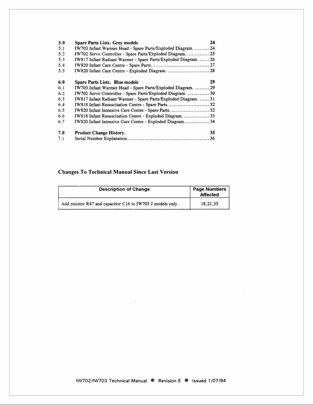
Changes
Add
resistor
Spare
Parts
IW703
[W702
[W817
IW320
[W820
Spare
Parts
[W703
IW702
1W817
1W818
[W820
[W818
[W820
Product
Serial
Number
To
Technical
R47
Lists.
Grey
models
Infant
Warmer
Servo
Controller - Spare
Infant
Radiant
Infant
Care
Infant
Care
Lists.
Infant
Warmer
Servo
Controller - Spare
Infant
Radiant
Infant
Resuscitation
Infant
Intensive
Infant
Resuscitation
Infant
Intensive
Change
Description
and
capacitor
Head - Spare
Warmer - Spare
Centre - Spare
Centre - Exploded
Blue
models
Head - Spare
Warmer - Spare
Centre - Spare
Care
Centre - Exploded
Care
History.
Explanatlon.................................
Manual
of
C16
Parts/Exploded
Parts/Exploded
Parts/Exploded
Parts.....................................
Diagram.
Parts/Exploded
Parts/Exploded
Parts/Exploded
Centre - Spare
Centre - Exploded
Since
Last
Change
to
[W703 J models
Diagram.
..........................
Diagram.
Parts.
.........................
Parts.........................
Diagram.
Diagram................
Version
only.
Diagram.
Diagram.
.........
..............
Diagram.
Diagram.
................
......
.........
..............
......
eee
Page
Affected
18,21,35
24
25
26
27
28
29
29
30
31
32
32
33
34
35
36
Numbers
IW702/IW703
Technical
Manual
№
Revision
E
%
Issued
1/07/94
Page 5
page
1
1.0
1.1
1.1.1
General
This
documentation
I
W702
Servo
IW703
As
The
Product
Catalogue
Dimensions:
Supply
Supply
Supply
Infant
fitted
to
[W703
Specifications.
voltage:
current:
frequency:
Specifications.
defines
Controller.
Warmer
an
1W817,
Infant
number:
Head.
TW818,
Warmer
1W703
Height
Width
Depth
Weight
230V + 20V
3.0 A maximum
6.0 A maximum
50 / 60
Head
115V + 15V
the
technical
or
[W820
provides
107mm
390mm
760mm
13kg
Hz
specifications
Infant
Warmer.
manual
control
—
~
at
230V
at
115V
of
of
the
the
IW703
600W
Infant
radiant
Warmer
heater
Head,
power.
and
the
1.1.2
Heater
Capacity:
Lights:
Operating
INSTALLATION
1.
General.
The
minimum
deliberately,
For
.
Power.
Ensure
supply.
OPERATION
1.
When
Head).
i.
li.
ii.
Instructions.
unit
attachment,
that
Ensure
fitted
Switch
Switch
The
warmer
SERVO
must
be
distance
by
accident,
please
power
the
with
on
power
on
lights,
mode
600W
26W
firmly
and
from
the
or
refer
supply
is
power
cord
an
[W702
by
depressing
if
required,
will
automatically
refer
to
section
securely
infant
by
misuse
IW817/1W818/1W820
the
same
is
Servo
located
is
maintained
of
any
as
that
specified
not a hazard
Controller
the
POWER
by
depressing
start
operating
'TW702
Servo
kind.
to
to
its
mounting
with
assembly
on
the
staff
and
(optional
button.
the
LIGHTS
in
SERVO
Controller - Operation’
surface
no
decrease
instructions.
unit.
Plug
patients.
accessory
button.
mode.
For
at
all
being
the
power
to
[W703
operating
(page
times,
possible,
cord
Infant
instructions
3).
so
that
into
Warmer
the
either
power
in
IW702/IW703
Technical
Manual
X
Revision E *
Issued
1/07/94
Page 6
page
2
v.
vi.
vii.
viii.
ix.
Warnings
2.
When
11.
111.
IV.
у.
vi.
vii.
viii.
Warnings
Operating
example,
Check
Servo
Preheat
Select
temperature.
Place
When
temperature
as a temperature
If
the
infant's
temperature
Temperature
not
Switch
Switch
Switch
Preheat
Select
temperature.
Place
We
procedure:
a.
b.
c.
d.
Allow
temperature
the
Use
Controller.
in
MANUAL
then
it
must
that
the
MANUAL
Controller
for
desired
the
operating
[W702
fitted
on
on
on
for
desired
the
recommend
Set
up
Wipe
cotton
Affix
navel
Cover
(800IW
Plug
4-5
temperature
only a Fisher & Paykel
are
ten
minutes
heat
infant
in
the
the
is
constantly
monitor.
Servo
skin
temperature
monitor.
Monitor.
with
an
power
by
lights,
if
heat
by
depressing
ten
minutes
heat
infant
in
the
use
the
TM101
off
any
or
gauze
the
skin
and
the
xiphoid
the
skin
102)
to
the
skin
sensor
minutes
constantly,
to
adjust
illuminated.
setting,
warmer
IW702
depressing
required,
setting
of
vernix
dampened
sensor
sensor
ensure a true
for
mode.
be
selected
mode
light
with
the
HEAT
between
crib.
in
MANUAL
monitored.
See
section
Controller
should
We
recommend
Servo
the
by
depressing
the
with
the
HEAT
between
crib.
the
Fisher & Paykel
temperature
caseosa
with
probe
process).
probe
probe
into
skin
temperature
adjusting
to
the
new
If
manual
by
depressing
is
Controller.
POWER
HEAT
monitoring
and
acetone
to
the
with a Fisher & Paykel
skin
the
the
manual
setting.
800IW007
control
the
on
both
the
CONTROL
1-10,
and
mode,
It
is
possible
'[W702
not
1-10,
temperature
Servo
fitted
be
monitored
the use
button.
the
LIGHTS
MODE
CONTROL
and
TM101
stains
from
(CH3COCH>3)
infant's
TM101
readings
heat
Skin
button.
unit.
abdominal
temperature
is
HEAT
[W703
knob
allow
it
is
to
use
Controller - Operation’
to
the
knob
allow
temperature
the
reading.
to
control
Sensor
required,
MODE
Infant
set
the
important
the
TW703
continuously
of
button.
set
the
sensor
stabilise.
accordingly.
to
button
Warmer
to
10.
unit
to
to
[W702
Infant
the
Fisher & Paykel
to
10.
unit
to
monitor
placement
or
other
median
Sun
Spot
monitor.
Monitor
Probe
pre-heat
reach a stable
ensure
Servo
reach a stable
appropriate
line
(800[W101)
with
to
MANUAL
Head
and
that
Controller
(page
Warmer
using
and
site
with
(halfway
the
Allow
4-5
the
the
an
the
solvent.
between
infant's
IW702
heater
mode.
the
IW702
operating
the
infant's
simply
3).
Head,
external
TM101
operating
following
absorbent
or
Sun
minutes
Servo
for
the
the
Dot
skin
for
To
ensure a true
Paykel
Sun
Spot
ALARM
The
IW703
Infant
Warmer
alarm
has
been
activated,
supply
and
consult a qualified
IW702/IW703
skin
temperature
(8001W101)
Head
has
the
warmer
technician,
Technical
or
Sun
an
audible
should
Manual
reading
Dot
not
or
contact
#
(8001W102).
cover
the
Skin
and
visual
OVERHEAT
be
used.
your
nearest
Revision E #
Sensor
Disconnect
Fisher
Issued
Probe
ALARM.
the
warmer
& Paykel
1/07/94
with a Fisher
If
the
overheat
from
power
dealer.
&
Page 7
page
3
1.2
1.2.1
1.2.2
IW702
As
The
600W
Product
Catalogue
Supply
Supply
Supply
Operating
OPERATION
I.
Servo
fitted
to
IW702
radiant
voltage:
current:
freguency:
Operation
1.
Ensure
il.
Switch
111.
Switch
The
Controller
digital
Controller.
the
[W703
Infant
Servo
Controller
power.
heater
Specifications.
number:
Instructions.
in
Servo
Mode.
skin
sensor
on
power
on
lights
warmer
will
display
will
automatically
will
Warmer.
provides
IW702
10V + IV“
0.5
A
50
/60
Hz
probe
is
not
on
[W703
Infant
if
desired,
automatically
read
by
'111',
Power
supplied
the
[W703
plugged
Warmer
depressing
start
go
through
'222',
...
from
Infant
Warmer
into
the
IW702
Head
by
the
LIGHTS
operating
an
initialisation
'999".
the
IW703
Head
Servo
depressing
button
in
SERVO
procedure.
Infant
Warmer.
with
servo
Controller.
the
POWER
on
IW703
mode
and
During
control
button.
Infant
the
this
(PID)
Warmer
IW702
procedure
of
the
Head.
Servo
the
An
the
audio
Test
then
VI.
Check
IW702
УП.
To
Preheat
Vili.
Place
radiant
IX.
Wipe
gauze
Affix
and
(8001W
XI.
Plug
XII.
Select
XII.
The
contro]
the
temperature.
infant's
.
Allow
audio
skin
alarm
the
IW702
read
that
Servo
preheat
for
the
warmer
off
dampened
the
the
xiphoid
101)
the
skin
SERVO
desired
(between
MUTE
actual
4-5
alarm
sensor
will
38.0
degrees
the
Controller
the
radiant
ten
infant
any
vernix
skin
sensor
or
sensor
mode
skin
button
On
skin
minutes
will
sound
and a 'Prb'
probe
is
disconnected.
sound
and
Servo
Controller
Celsius
SERVO
minutes
is
Sun
mode
are
warmer,
with
in
the
crib.
appropriate.)
caseosa
with
acetone
probe
process).
(8001W102)
Dot
probe
into
on
IW703
temperature
32
and
37
degrees
down
for
releasing
temperature
for
the
skin
message
can
be
silenced
by
depressing
(plus
or
minus
indication
illuminated.
switch
to
the
HEAT
CONTROL
(Ensure
and
(CH3COCH3)
to
the
Cover
the
Infant
can
3
seconds,
the
within
temperature
stains
from
infant's
the
to
IW702
Warmer
be
Celsius).
and
MUTE
2
the
skin
ensure
set
seconds.
will
The
red
for
6
the
0.2
lights
on
MANUAL
manually
the
sensor
or
other
abdominal
sensor
true
a
Servo
Controller
Head
using
The
the
flashing
button,
readings
show
on
disconnect
minutes
TEST
degrees
both
the
mode
knob
set
placement
appropriate
median
probe
skin
by
depressing
the
IW702
set
temperature
digital
the
display
to
stabilise.
by
Celsius
on
set
heat
with
temperature
the
digital
light
will
depressing
button.
SKIN
The
after 5 seconds).
IW703
Infant
the
IW703
to
10.
level
currently
site
solvent.
line
(halfway
a
Fisher
SENSOR
the
Servo
Controller's
can
display
reverts
display
flash
on
the
MUTE
digital
Warmer
Infant
with
absorbent
between
&
Paykel
reading.
SOCKET.
HEAT
MODE
be
displayed
indicates
back
to
to
indicate
and
display
Warmer
controlling
temperature
the
indicating
off.
button.
should
Head
Head.
cotton
the
navel
Sun
Spot
button.
by
holding
desired
that
The
and
the
set
the
or
IW702/IW703
Technical
Manual
®
Revision E #
Issued
1/07/94
Page 8
page
4
2.
Operation
111.
3.
Routine
It
is
operating
in
Manual
With
the
skin
Controller
The
With
Controller
on
except
recommended
can
heat
output
the
skin
will
the
[W702
the
[W703
Calibration
within
be
sensor
go
Servo
that
its
design
Mode.
sensor
probe
used
as a temperature
can
be
controlled
probe
into
Unmonitored
Controller
Infant
Warmer
Check
of
Skin
the
Skin
specifications.
plugged
manually
not
plugged
will
Head
Sensor
Sensor
in
monitor
MANUAL
flash,
overheat
Probe.
Probe
and
MANUAL
to
with
the
in
and
the
temperature
alarm,
is
checked
display
HEAT
the
mode.
every
mode
infant
CONTROL
MANUAL
The
display
will
be
selected,
skin
mode
green
MANUAL
will
inhibited.
three
months
the
IW702
temperature.
knob.
selected,
mode
be
blank
and
to
ensure
Servo
the
Servo
indicator
all
alarms,
that
it
is
11.
lil.
iv.
v.
vi.
Warnings
ALARMS
The
1.
5.*
Obtain a good
Place a thermometer
water
which
Switch
Plug
the
37
degrees
Allow
compare
The
LED
then
it
Please
with
regard
Use
only a Fisher & Paykel
Controller.
To
ensure a true
Paykel
IW702
High
Temperature
greater
Low
Temperature
less
than
Note:
temperature
minutes
Skin
Sensor
probe
has
Incorrect
readings
discarded.
In
Unmonitored
minutes
flashing
*
This
quality
is
between
on
an
IW703
Skin
Sensor
Celsius.
the
temperature
the
temperature
display
is
recommended
also
refer
to
Skin
Sun
Spot
Servo
Controller
than
that
that
set.
The
low
reading
with
PCI
Probe
been
Skin
from
the
an
audible
green
MANUAL
option
refers
should
to
Sensor
skin
(8001W101)
(high
set.
(low
temperature
selected)
Failure
disconnected
Sensor
two
MANUAL
mercury
and
Infant
Probe
the
is
within
skin
intermittent
to
the
thermometer.
the
probe
30
degrees
Warmer
into
the
of
the
Skin
on
the
LED
be
within + 0.5
that
the
Skin
IW702/IW703
Probe
temperature
or
has
audible
temperature
temperature
alarm
0.8
of
Disconnect
from
Probe
Reading
sensor
mode
mode
indicator
version
cup
end
of
Celsius
and
Head
IW702
Servo
Sensor
Probe
display
degrees
Sensor
Technical
calibration
8001W007
reading
Sun
Dot
(8001W102).
and
visual
light
and
light
and
is
disabled
degrees
the
probe
with
beep
2.5
of
('Prb'
Servo
('E20'
beads
PC1
alarm.
during
software
the
Skin
38
degrees
which
has
Controller
and
of
the
IW702
Celsius
Probe
be
Manual,
checks.
Skin
Sensor
cover
the
alarms
audible
audible
during
the
set
point
display
Controller
display
do
not
selected
At
15
non-monitored
only
Sensor
Probe
into a container
Celsius.
an
IW702
thermometer
to
of
replaced.
Section
Skin
for
the
alarm) - temperature
alarm) - temperature
warm-up.
or
and
or
has
and
match - the
(No
alarms
minutes a continuous
Servo
and
set
the
temperature
to
stabilise.
the
reading
the
thermometer
4.3
for
Probe
with
Sensor
Probe
following
30
audible
malfunctioned.
audible
conditions:
It
is
enabled
minutes
alarm) - the
alarm) - the
skin
sensor
with
PC1
operation.
Controller
of
from
of
attached.
control
Once
the
thermometer.
reading.
further
information
the
[W702
with a Fisher
is 1 degree
is 1 degree
probe
open
audio
Celsius
Celsius
when
the
switch
on.
skin
temperature
should
circuit)
alarm
warm
to
stable,
If
not,
Servo
&
skin
(15
sensor
be
at
12
and
IW702/1W703
Technical
Manual
*
Revision E %*
Issued
1/07/94
Page 9
page
5
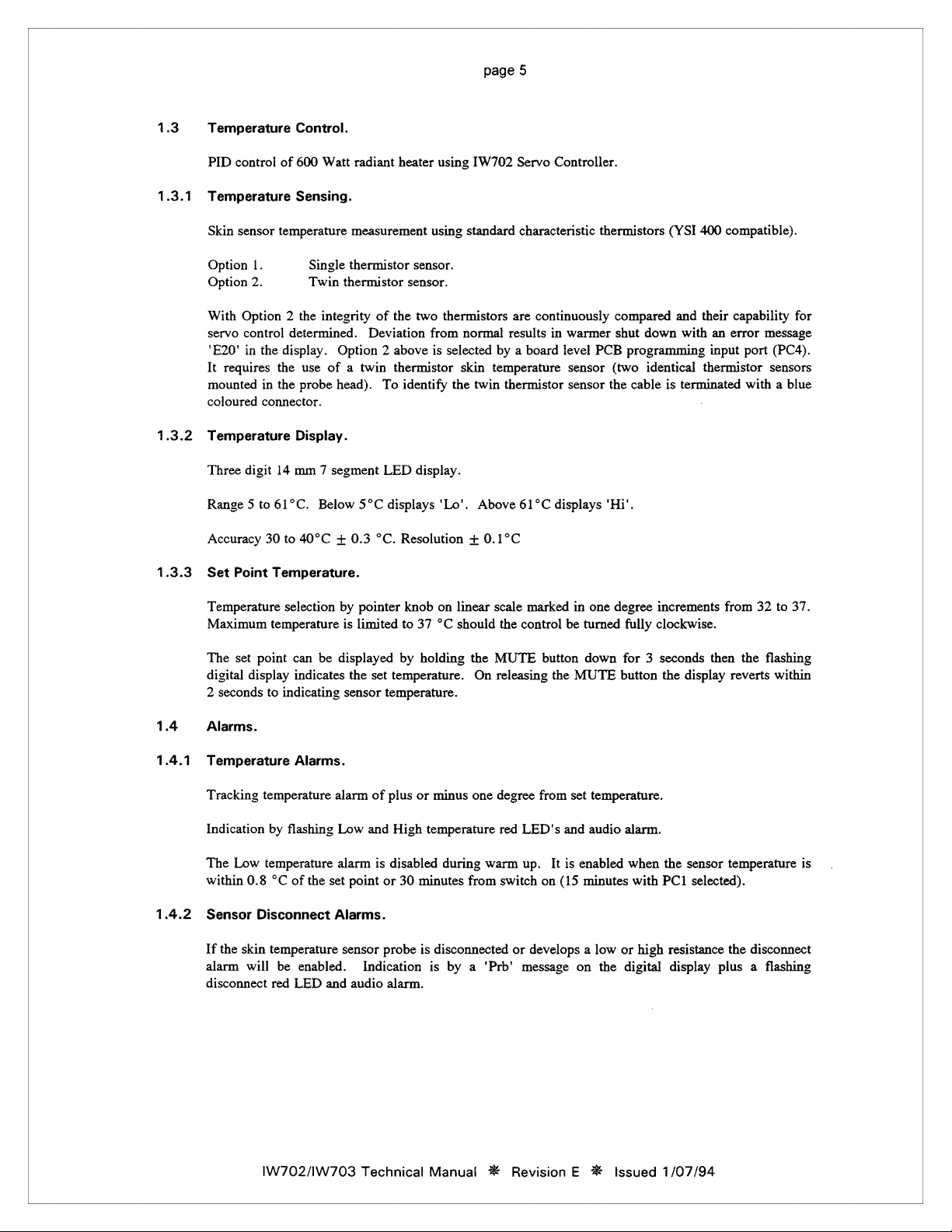
1.3
1.3.1
1.3.2
1.3.3
Temperature
PID
control
Temperature
Skin
sensor
Option
1.
Option
2.
With
Option 2 the
servo
control
"E20"
in
the
It
requires
mounted
coloured
Temperature
Three
Range 5 to
Accuracy
Set
in
connector.
digit
30
Point
Control.
of
600
Watt
Sensing.
temperature
Single
Twin
integrity
determined.
display.
the
the
14
61°C.
to
Temperature.
Option 2 above
use
of a twin
probe
head).
Display.
mm 7 segment
Below 5°C
40°C + 0.3 °C.
radiant
heater
measurement
thermistor
thermistor
of
the
Deviation
thermistor
To
identify
LED
displays
Resolution + 0.1°C
using
using
sensor.
sensor.
two
thermistors
from
is
selected
display.
'Lo'.
[W702
standard
normal
skin
the
twin
Above
Servo
Controller.
characteristic
are
continuously
results
in
by a board
temperature
thermistor
61°C
level
displays
thermistors
warmer
PCB
sensor
sensor
compared
shut
down
programming
(two
identical
the
cable
'Hi'.
(YSI
400
and
their
with
an
input
thermistor
is
terminated
compatible).
capability
error
port
with a blue
for
message
(PC4).
sensors
1.4
1.4.1
1.4.2
Temperature
Maximum
The
digital
2
seconds
Alarms.
Temperature
Tracking
Indication
The
within
Sensor
If
the
alarm
disconnect
temperature
set
point
display
to
temperature
by
Low
temperature
0.8
°C
Disconnect
skin
temperature
will
red
selection
can
be
indicates
indicating
Alarms.
alarm
flashing
of
the
set
Alarms.
be
enabled.
LED
and
by
pointer
is
limited
displayed
the
set
temperature.
sensor
temperature.
of
plus
Low
and
High
alarm
is
disabled
point
or
sensor
probe
Indication
audio
alarm.
knob
on
to
37
°C
by
holding
or
minus
temperature
30
minutes
is
disconnected
is
linear
scale
should
the
the
MUTE
On
releasing
one
degree
red
during
warm
from
switch
by a 'Prb'
marked
control
be
button
the
from
set
LED's
and
up.
It is
on (15
or
develops a low
message
in
one
degree
turned
fully
down
for 3 seconds
MUTE
button
temperature.
audio
alarm.
enabled
minutes
or
on
the
digital
increments
clockwise.
the
when
the
with
PC1
high
from
then
display
resistance
display
reverts
sensor
temperature
selected).
the
plus a flashing
32
to
37.
the
flashing
within
disconnect
is
IW702/1W703
Technical
Manual
#
Revision E %
Issued
1/07/94
Page 10
page
6
Audio
1.4.3
Alarm.
A
choice
of
programming
A
momentary
LED
indicators
within a mute
the
ISO
input
port
depression
remain
delay
draft
(PCO).
flashing
will
cause
standard
of
the
MUTE
until
the
audio
the
audio
alarm
button
alarm
alarm
or a gliding
will
silence
condition
to
be
re-enabled.
tone
can
the
audio
clears.
be
alarm
Any
new
selected
by a board
for 6 minutes.
alarm
condition
level
The
relevant
occurring
PCB
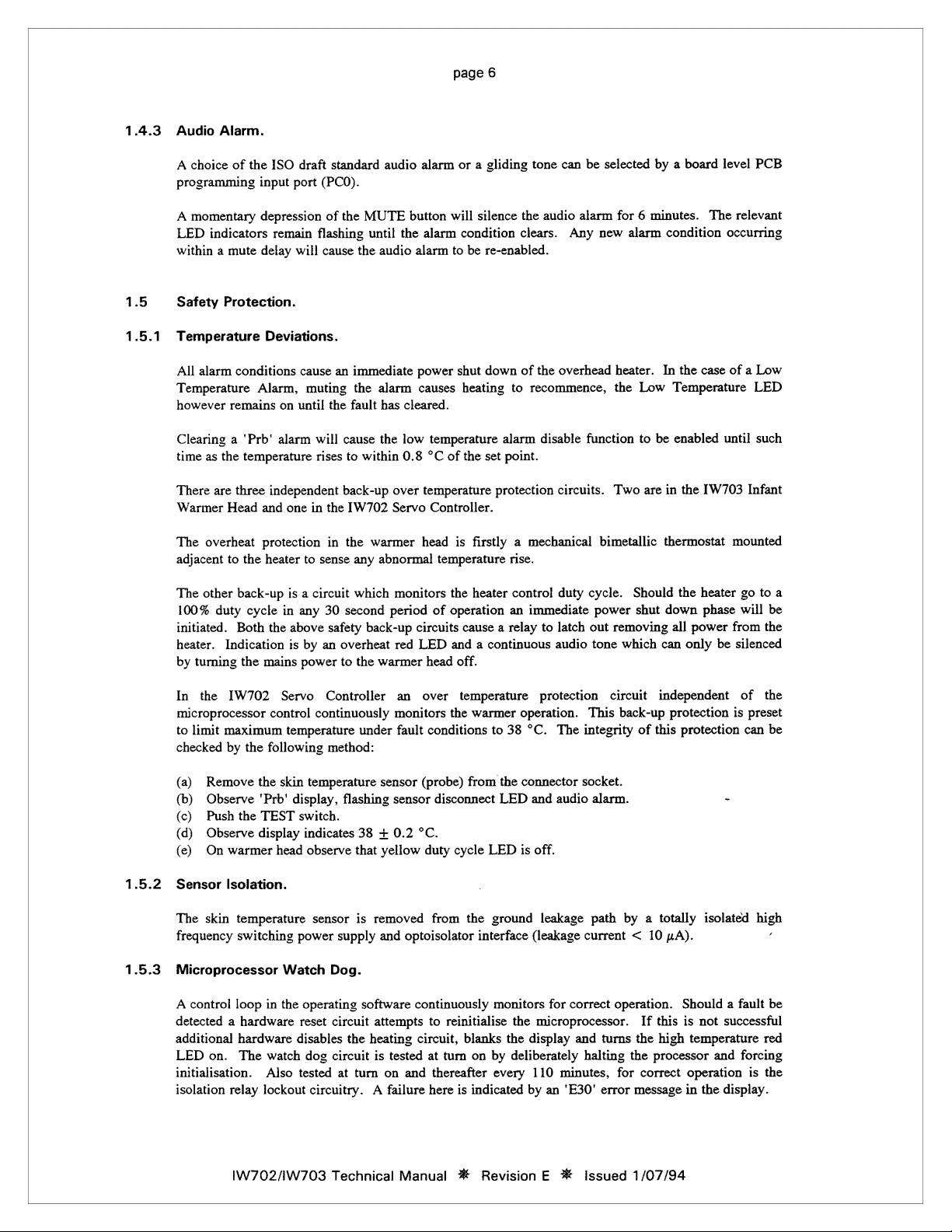
1.5
1.5.1
Safety
Protection.
Temperature
All
alarm
Temperature
however
Clearing a 'Prb'
time
as
There
are
Warmer
The
overheat
adjacent
The
other
100%
duty
initiated.
heater.
by
turning
In
the
microprocessor
to
limit
checked
Deviations.
conditions
Alarm,
remains
the
temperature
three
independent
Head
and
protection
to
the
heater
back-up
cycle
Both
the
Indication
the
mains
IW702
control
maximum
by the
following
cause
an
muting
on
until
the
alarm
will
rises
one
in
the
in
to
sense
is a circuit
in
any
30
above
safety
is
by
an
overheat
power
to
Servo
Controller
continuously
temperature
method:
immediate
the
alarm
fault
has
cause
the
to
within
back-up
IW702
the
warmer
any
abnormal
which
second
period
back-up
the
warmer
under
power
causes
cleared.
low
temperature
0.8
°C
over
temperature
Servo
Controller.
head
temperature
monitors
of
circuits
red
LED
head
an
over
monitors
fault
conditions
shut
down
of
the
heating
of
the
is
the
operation
cause a relay
and a continuous
off.
temperature
the
to
recommence,
alarm
disable
set
point.
protection
firstly a mechanical
rise.
heater
contro]
an
immediate
to
protection
warmer
operation.
to
38
°C.
overhead
function
circuits.
bimetallic
duty
cycle.
power
latch
out
audio
tone
This
The
integrity
heater.
the
Low
to
be
Two
are
Should
shut
removing
which
circuit
back-up
of
this
In
the
case
of a Low
Temperature
enabled
in
thermostat
down
all
can
independent
protection
until
the
[W703
the
heater
phase
power
only
be
protection
LED
such
Infant
mounted
go
to
a
will
be
from
the
silenced
of
the
is
preset
can
be
(a)
Remove
(b)
Observe
(c)
Push
(d)
Observe
(e)
On
1.5.2
1.5.3
Sensor
The
skin
frequency
Microprocessor
A
control
detected a hardware
additional
LED
on.
initialisation.
isolation
the
skin
'Prb'
the
TEST
display
warmer
Isolation.
relay
head
temperature
switching
Watch
loop
in
the
hardware
The
watch
Also
lockout
IW702//W703
temperature
display,
switch.
indicates
observe
power
operating
reset
disables
dog
tested
circuitry. A
flashing
sensor
supply
Dog.
circuit
the
circuit
at
Technical
sensor
sensor
38 + 0.2
that
yellow
is
removed
and
software
attempts
heating
is
tested
turn
on
failure
Manual
(probe)
from
disconnect
°C.
duty
cycle
from
the
optoisolator
continuously
to
circuit,
at
and
here
interface
reinitialise
blanks
turn
on
thereafter
is
indicated
№
Revision E #
the
connector
LED
and
LED
is
ground
(leakage
monitors
the
the
display
by
deliberately
every
110
by
socket.
audio
alarm.
off.
leakage
microprocessor.
for
correct
and
minutes,
an
'E30'
path
by a totally
current < 10
operation.
turns
halting
the
for
error
Issued
pA).
If
this
the
high
processor
correct
message
1/07/94
-
isolated
Should a fault be
is
not
temperature
operation
in
the
high
successful
red
and
forcing
is
the
display.
Page 11
page
7
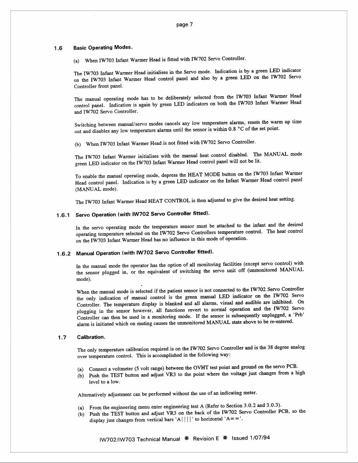
Basic
1.6
Operating
When
(a)
IW703
The
IW703
the
on
Controller
manual
The
JW702
and
When
(b)
IW703
The
green
enable
To
Head
(MANUAL
1W703
The
panel.
disables
LED
control
contro!
and
Switching
out
Modes.
Infant
IW703
Warmer
Infant
Infant
panel.
front
operating
Indication
Controller.
Servo
between
any
Infant
IW703
Infant
indicator
manual
the
panel.
mode).
Warmer
Infant
Warmer
initialises
Head
Warmer
manual/servo
low
Warmer
on
operating
Indication
Head
has
mode
again
is
temperature
Warmer
initialises
[W703
the
mode,
is
Head
Head
control
be
to
by
modes
alarms
Head
Infant
by
HEAT
fitted
is
the
in
panel
deliberately
LED
green
cancels
until
not
is
the
with
Warmer
depress
green
a
CONTROL
with
Servo
and
indicators
any
the
with
fitted
manual
Head
HEAT
the
indicator
LED
[W702
mode.
also
selected
temperature
low
sensor
[W702
heat
control
MODE
then
is
Controller.
Servo
Indication
green
a
by
from
both
on
within
is
Servo
control
panel
button
Infant
the
on
adjusted
by
is
LED
IW703
the
[W703
the
alarms,
of
°C
0.8
Controller.
disabled.
not
will
the
on
Warmer
the
give
to
green
a
on
Infant
Infant
resets
set
the
The
lit.
be
[W703
Head
desired
LED
[W702
the
Warmer
Warmer
warm
the
point.
MANUAL
Infant
heat
indicator
Servo
up
Warmer
control
setting.
Head
Head
time
mode
panel
1.6.1
1.6.2
1.7
Operation
Servo
servo
the
In
operating
on
Manual
In
the
mode).
When
the
Controller.
plugging
Controller
alarm
Calibration.
The
over
(a)
(b)
temperature
1W703
the
Operation
manual
the
sensor
manual
the
indication
only
in
initiated
is
temperature
only
temperature
Connect
Push
level
to
(with
operating
Infant
mode
plugged
mode
temperature
The
sensor
the
then
can
which
control.
voltmeter
a
TEST
the
a
low.
IW702
mode
selected
Warmer
(with
the
in,
be
Head
IW702
operator
the
or
selected
is
manual
of
display
however,
in
used
muting
on
calibration
This
volt
(5
and
button
Servo
temperature
the
[W702
the
on
no
has
Servo
the
has
equivalent
the
if
control
is
all
monitoring
a
causes
required
accomplished
is
range)
adjust
Controller
sensor
Servo
influence
Controller
of
option
switching
of
sensor
patient
the
is
blanked
functions
mode.
unmonitored
the
the
on
is
in
between
to
VR3
fitted).
must
Controllers
this
in
fitted).
monitoring
all
is
manual
green
all
and
revert
If
IW702
following
the
OVHT
the
point
the
attached
be
mode
servo
the
connected
not
alarms,
normal
to
sensor
the
MANUAL
Servo
test
where
to
temperature
operation.
of
facilities
off
unit
to
indicator
LED
and
visual
operation
subsequently
is
state
Controller
way:
ground
and
point
voltage
the
infant
the
servo
IW702
on
and
unplugged,
to
the
is
on
changes
The
the
are
the
be
the
control.
(except
(unmonitored
the
audible
above
and
just
desired
the
and
control
heat
control)
MANUAL
Controller
Servo
[W702
inhibited.
[W702
a
re-entered.
analog
degree
38
PCB.
servo
a
from
with
Servo
On
Servo
'Prb'
high
indicating
an
of
use
on
'A|
the
test
back
the
|'
||
Revision
#
(Refer
A
the
of
horizontal
to
to
E
performed
be
button
changes
can
enter
menu
adjust
and
vertical
from
Technical
Alternatively
From
(a)
Push
(b)
display
adjustment
engineering
the
TEST
the
just
IW702/IW703
without
engineering
VR3
bars
Manual
Section
IW702
'A==".
Issued
#
meter.
3.0.2
Servo
3.0.3).
and
Controller
1/07/94
PCB,
so
the
Page 12
page
8
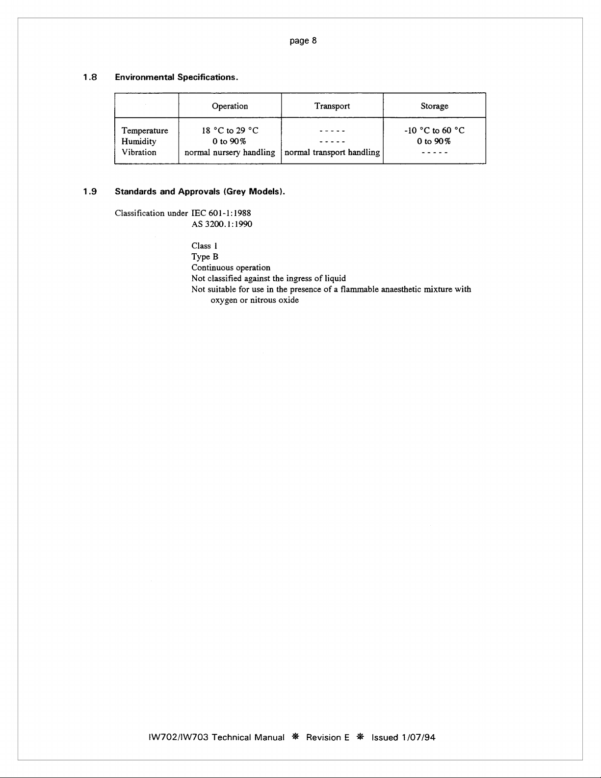
1.8
1.9
Environmental
Temperature
Humidity
Vibration
Standards
Classification
and
Specifications.
18
normal
Approvals
under
IEC
601-1:1988
AS
3200.1:1990
Class
Type
Continuous
Not
classified
Not
suitable
oxygen
Operation
°Cto
29
0t090%
nursery
B
handling | normal
(Grey
1
operation
for
or
°C
Models).
against
use
in
nitrous
|
|
the
ingress
the
oxide
Transport
-----
—-----
transport
of
presence
handling
liquid
of a flammable
Storage
-10
°C
0
to
|
-----
anaesthetic
mixture
to
90%
60
°C
with
IW702/IW703
Technical
Manual
*
Revision E #
Issued
1/07/94
Page 13
page
9
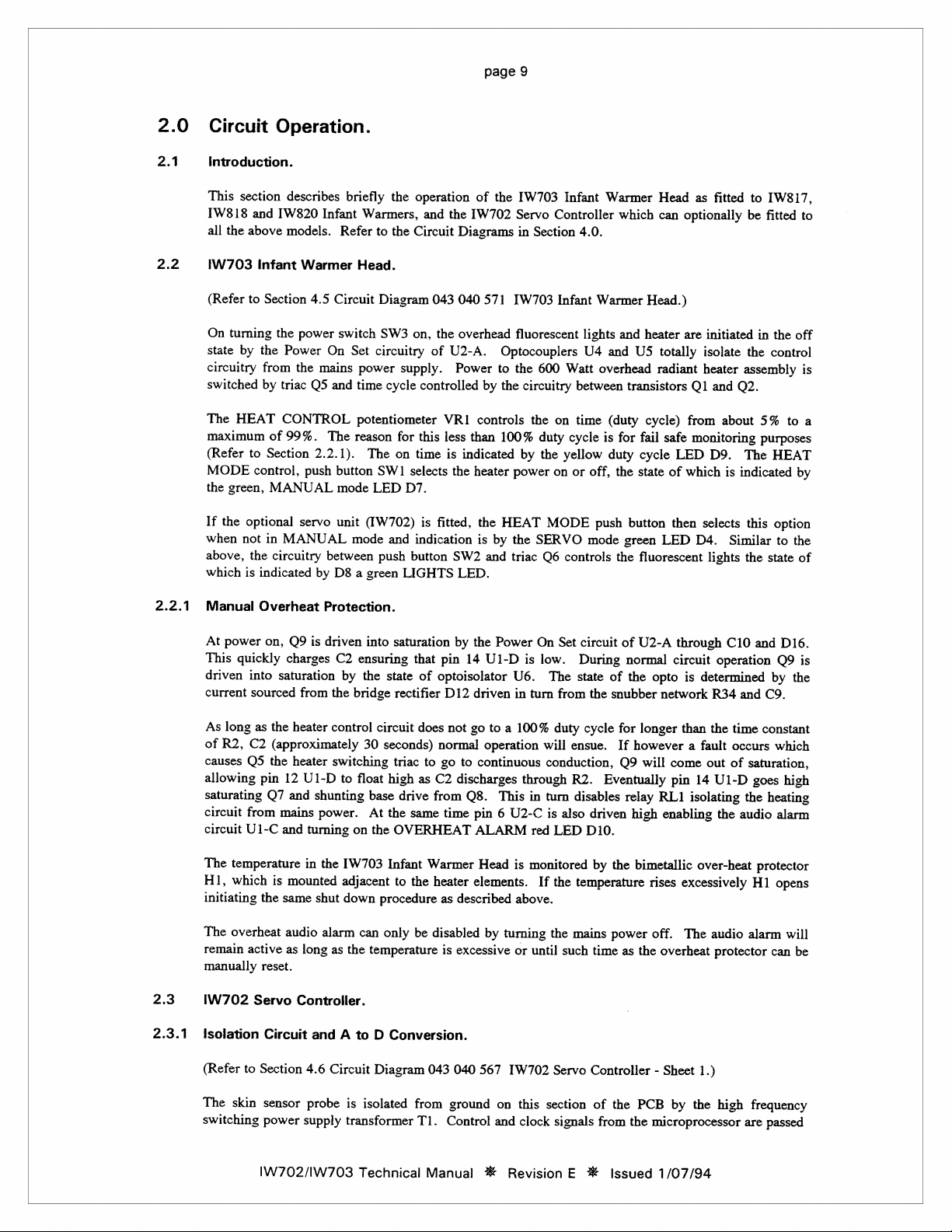
2.0
2.1
2.2
Circuit
Introduction.
This
section
[W818
and
all
the
above
IW703
(Refer
On
state
circuitry
switched
The
maximum
(Refer
MODE
the
If
when
above,
which
Infant
to
turning
by
HEAT
to
control,
green,
the
optional
not
the
Is
Section
the
from
by
of
Section
MANUAL
in
circuitry
indicated
Operation.
describes
[W820
models.
the
power
Power
the
triac
CONTROL
99%.
servo
MANUAL
Infant
Warmer
4.5
Circuit
On
mains
Q5
and
The
2.2.1).
push
button
between
by
D8 a green
briefly
Refer
Head.
switch
Set
power
time
potentiometer
reason
mode
unit
mode
the
Warmers,
to
the
Diagram
SW3
circuitry
supply.
cycle
for
The
on
SW1
selects
LED
D7.
(W702)
and
push
button
LIGHTS
operation
and
the
IW702
Circuit
Diagrams
043
040
on,
the
overhead
of
U2-A.
Power
controlled
VR1
this
less
than
time
is
indicated
the
is
fitted,
indication
SW2
LED.
of
the
[W703
Servo
in
571
IW703
fluorescent
Optocouplers
to
the
by
the
circuitry
controls
100%
by
heater
power
the
HEAT
is
by
the
and
triac
Infant
Controller
Section
Infant
600
Watt
the
on
duty
cycle
the
yellow
on
or
MODE
SERVO
Q6
controls
Warmer
4.0.
Warmer
lights
U4
and
overhead
between
time
(duty
is
for
duty
off,
the state
push
mode
the
Head
which
can
optionally
Head.)
and
heater
are
U5
totally
radiant
transistors
cycle)
fail
safe
cycle
LED
of
button
then
green
LED
fluorescent
as
fitted
initiated
isolate
heater
assembly
Q1
and
Q2.
from
about
monitoring
D9.
The
which
is
indicated
selects
D4.
Similar
lights
the
to
IW817,
be
fitted
in
the
the
control
5%
purposes
HEAT
this
option
to
state
to
the
to
off
is
a
by
of
2.2.1
2.3
2.3.1
Manual
At
This
driven
current
As
of
causes
allowing
saturating
circuit
circuit
The
HI,
initiating
The
remain
manually
IW702
isolation
Overheat
power
on,
guickly
into
sourced
long
as
R2,
C2
Q5
pin
Q7
from
U1-C
temperature
which
the
overheat
active
reset.
Servo
Circuit
Protection.
Q9
is
driven
charges
saturation
the
(approximately
the
12
and
mains
and
mounted
is
same
audio
as
C2
ensuring
by
from
the
bridge
heater
control
heater
switching
U1-D
to
float
shunting
power.
turning
on
in
the
[W703
adjacent
down
shut
can
alarm
the
as
long
Controller.
to
A
and
into
saturation
that
the
state
of
rectifier
circuit
does
30
seconds)
triac
to
high
as
base
drive
At
the
same
the
OVERHEAT
Infant
Warmer
the
to
procedure
be
only
temperature
Conversion.
D
by
the
Power
pin
14
U1-D
optoisolator
D12
driven
not
go
to a 100%
normal
operation
go
to
continuous
C2
discharges
from
Q8.
time
pin 6 U2-C
ALARM
Head
elements.
heater
described
as
disabled
by
excessive
is
On
is
U6.
in
turn
through
This
in
red
is
monitored
above.
turning
until
or
Set
circuit
low.
During
The
state
from
the
duty
cycle
will
ensue.
conduction,
R2.
turn
disables
is
also
driven
LED
D10.
by
temperature
the
If
mains
the
time
such
of
U2-A
normal
of
the
opto
snubber
Eventually
the
power
network
for
longer
If
however a fault
Q9
will
come
pin
relay
RL1
high
enabling
bimetallic
rises
off.
overheat
the
as
through
circuit
than
C10
operation
is
determined
R34
the
time
occurs
out
of
14
U1-D
isolating
the
over-heat
excessively
audio
The
protector
and
D16.
O9
by
the
and
C9.
constant
which
saturation,
goes
high
the
heating
audio
alarm
protector
opens
H1
will
alarm
can
is
be
4.6
Section
to
(Refer
probe
sensor
skin
The
switching
power
supply
IW702/IW703
Diagram
Circuit
isolated
is
transformer
Technical
Servo
TW702
567
040
043
section
this
ground
from
T1.
Control
Manual # Revision E #
on
and clock
signals
Controller
PCB
the
of
from
the
Issued
1.)
Sheet
-
high
the
by
microprocessor
1/07/94
are
frequency
passed
Page 14
page
10
to
this
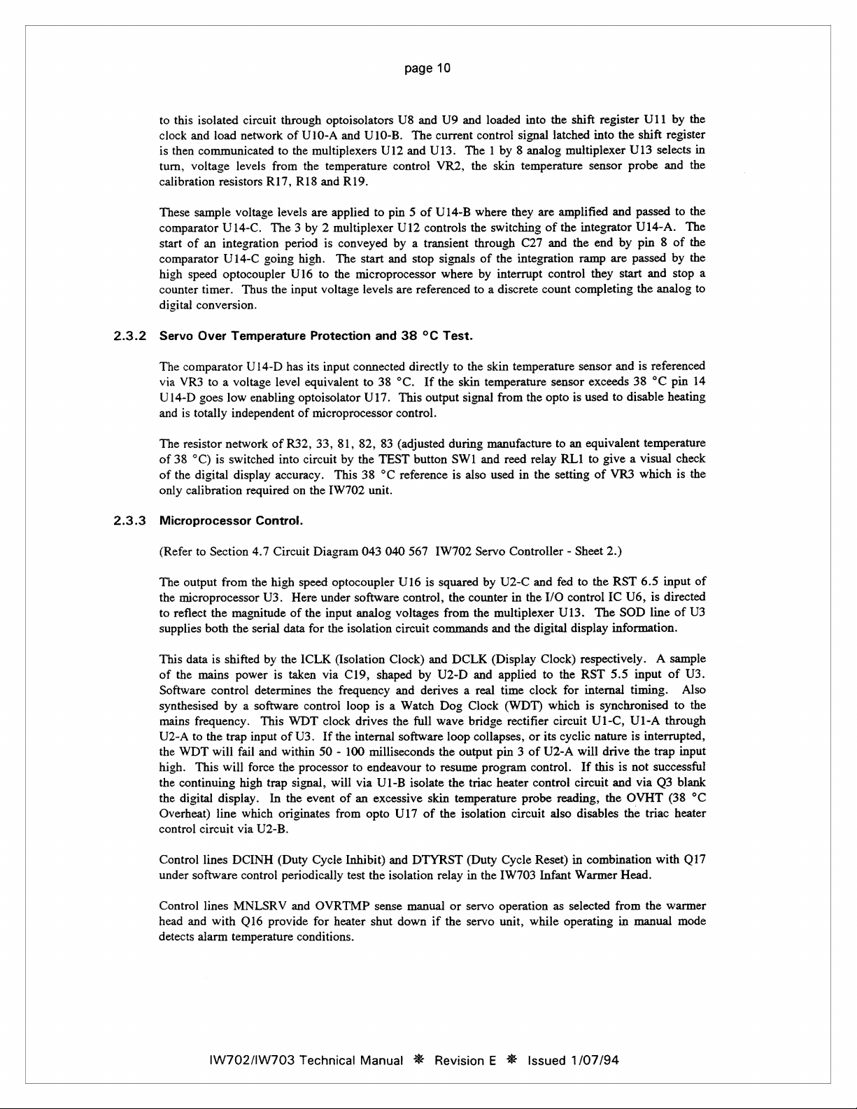
2.3.2
isolated
clock
and
is
then
communicated
turn,
voltage
calibration
These
sample
comparator
start
of an
comparator
high
speed
counter
digital
conversion.
Servo
Over
The
comparator
via
VR3
U14-D
goes
and
is
totally
circuit
load
network
levels
resistors
voltage
U14-C.
integration
U14-C
optocoupler
timer.
Thus
Temperature
U14-D
to a voltage
low
enabling
independent
through
to
from
R17,
levels
The 3 by 2 multiplexer
going
the
level
optoisolators
of
U10-A
and
the
multiplexers
the
temperature
RI8
and
are
applied
period
is
conveyed
high.
The
U16
to
the
input
voltage
Protection
has
its
input
equivalent
optoisolator
of
microprocessor
U10-B.
U12
R19.
to
start
microprocessor
levels
and
connected
to
38
U17.
U8
and
U9
and
The
current
and
U13.
The 1 by 8 analog
control
pin 5 of
by a transient
and
U12
controls
stop
are
referenced
38
°C
directly
°C.
If
This
output
control.
VR2,
U14-B
signals
where
Test.
to
the
skin
signal
loaded
control
signal
the
skin
where
they
the
switching
through
of
the
integration
by
interrupt
to a discrete
the
skin
temperature
temperature
from
into
the
shift
latched
multiplexer
temperature
are
amplified
of
the
integrator
C27
and
the
ramp
control
count
completing
sensor
sensor
the
opto
is
used
register
into
the
sensor
and
end
by
are
they
start
and
exceeds
to
U11
shift
U13
selects
probe
and
passed
U14-A.
pin 8 of
passed
and
the
analog
is
referenced
38
°C
disable
by
the
register
in
the
to
the
The
the
by
the
stop
a
to
pin
14
heating
2.3.3
The
resistor
network
of
38
°C)
is
switched
of
the
digital
only
calibration
Microprocessor
(Refer
to
Section
The
output
from
the
microprocessor
to
reflect
the
supplies
This
of
Software
synthesised
mains
U2-A
the
high.
the
the
Overheat)
control
both
data
is
the
mains
control
by a software
frequency.
to
the
WDT
will
This
will
continuing
digital
display.
line
circuit
shifted
trap
of
into
display
accuracy.
required
Control.
4.7
Circuit
the
high
U3.
magnitude
the
serial
by
the
power
is
determines
This
input
of
fail
and
within
force
the
high
trap
In
which
originates
via
U2-B.
R32,
33,
circuit
on
the
Diagram
speed
Here
of
the
data
for
ICLK
taken
the
control
WDT
U3.
50 - 100
processor
signal,
the
event
81,
82,
by
the
This
38
[W702
unit.
043
optocoupler
under
software
input
analog
the
isolation
(Isolation
via
C19,
frequency
loop
clock
drives
If
the
internal
milliseconds
to
endeavour
will
via
of an
excessive
from
opto
83
(adjusted
TEST
button
°C
reference
040
567
U16
control,
voltages
circuit
Clock)
shaped
is a Watch
U1-B
by
and
derives a real
the
full
software
isolate
U17
of
during
SW1
is
IW702
is
squared
the
from
commands
and
DCLK
U2-D
Dog
wave
loop
the
output
to
resume
the
skin
temperature
the
isolation
manufacture
and
reed
also
used
Servo
by
U2-C
counter
the
multiplexer
and
(Display
and
applied
time
Clock
(WDT)
bridge
rectifier
collapses,
pin 3 of
program
triac
heater
to
an
equivalent
relay
RLI
to
in
the
setting
of
Controller - Sheet
and
fed
to
the
in
the
I/O
control
U13.
The
the
digital
display
Clock)
respectively. A sample
to
the
RST
clock
for
internal
which
is
circuit
U1-C,
or
its
cyclic
nature
U2-A
will
control.
control
probe
circuit
If
circuit
reading,
also
disables
this
temperature
give a visual
VR3
which
2.)
RST
6.5
input
IC
U6,
is
directed
SOD
line
information.
5.5
input
timing.
synchronised
U1-A
is
interrupted,
drive
the
trap
is
not
successful
and
via
Q3
the
OVHT
the
triac
check
is
the
of
of
U3
of
U3.
Also
to
the
through
input
blank
(38
°C
heater
Control
under
Control
head
detects
lines
software
lines
and
with
alarm
IW702/IW703
DCINH
MNLSRV
temperature
(Duty
control
Q16
provide
Cycle
Inhibit)
periodically
and
conditions.
Technical
OVRTMP
for
heater
test
and
the
isolation
sense
shut
Manual
DTYRST
manual
down
№
(Duty
relay
in
the
or
servo
operation
if
the
servo
Revision E X
Cycle
[W703
unit,
Reset)
Infant
as
while
Issued
in
combination
Warmer
selected
operating
1/07/94
from
Head.
in
manual
with
the
Q17
warmer
mode
Page 15
page
11
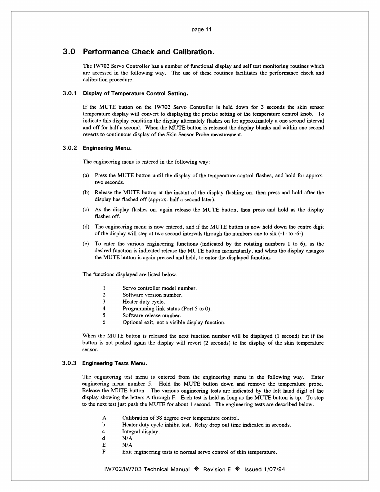
3.0
3.0.1
3.0.2
Performance
The
[W702
Servo
are
accessed
calibration
Display
If
the
temperature
indicate
and
off
reverts
Engineering
The engineering
(a)
Press
two
(b)
Release
display
(ο)
As
flashes
(d)
The
of
(e)
To
desired
the
in
procedure.
of
Temperature
MUTE
display.
this
display
for
half a second.
to
continuous
Menu.
the
MUTE
seconds.
the
has
the
display
off.
engineering
the
display
enter
the
function
MUTE
Check
Controller
the
following
button
on
will
condition
display
menu
is
button
MUTE
flashed
flashes
menu
will
various
is
button
has a number
way.
Control
the
[W702
convert
the
When
of
entered
until
button
off
(approx.
on,
is
now
step
at
two
engineering
indicated
is
again
and
Calibration.
The
Setting.
Servo
to
displaying
display
the
MUTE
the
Skin
Sensor
in
the
following
the
display
at
the
instant
half a second
again
release
entered,
second
functions
release
the
pressed
and
of
functional
use
of
these
Controller
the
precise
alternately
button
and
intervals
MUTE
held,
is
Probe
way:
of
the
of
the
later).
the
MUTE
if
the
through
(indicated
to
enter
flashes
released
temperature
display
button
display
routines
measurement.
MUTE
and
facilitates
is
held
down
setting
on
for
the
flashing
button,
button
the
numbers
by
the
momentarily,
the
displayed
of
control
self
test
monitoring
the
performance
for 3 seconds
the
temperature
approximately a one
display
blanks
and
on,
then
press
is
now
one
rotating
and
function.
flashes,
then
and
press
and
hold
held
down
to
six (-1-
numbers 1 to
when
the
routines
the
skin
control
second
within
one
hold
for
and
hold
as
the
the
centre
to
-6-).
display
which
check
sensor
knob.
interval
second
approx.
after
display
digit
6), as
changes
and
To
the
the
3.0.3
The
functions
When
button
sensor.
Engineering
The engineering
engineering
Release
display
to
the
next
m
D
D
Db
U
O
the
MUTE
is
not
menu
the
MUTE
showing
test
A
b
ο
d
E
F
displayed
pushed
Tests
the
just
Calibration
Heater
Integral
N/A
N/A
Exit
are
listed
Servo
controller
Software
Heater
Programming
Software
Optional
button
test
version
duty
cycle.
release
exit,
is
released
again
the
Menu.
menu
is
number
push
5.
button.
letters A through
The
the
MUTE
of
duty
cycle
display.
engineering
below.
model
number.
number.
link
status
(Port 5 to
number.
not a visible
display
entered
Hold
various
for
38
degree
inhibit
tests
display
the
next
will
from
the
MUTE
engineering
F.
Each
about 1 second.
over
test.
to
normal
0).
function.
function
revert
(2
seconds)
the
engineering
button
tests
test
is
held
temperature
Relay
drop
servo
number
down
are
as
The
engineering
control.
out
control
will
be
to
the
menu
and
indicated
long
as
time
indicated
of
skin
displayed
display
remove
the
temperature.
in
the
by
the
MUTE
tests
of
following
the
are
in
(1
second)
the
skin
temperature
left
hand
button
is
described
seconds.
but
if
the
temperature
way.
Enter
probe.
digit
of
the
up.
To
step
below.
IW702/IW703
Technical
Manual
*
Revision E *
Issued
1/07/94
Page 16
page
12
If
the
normal
this
mode
MUTE
button
software
during
is
control
clinical
not
touched
loop
is
interrupted
operating
for 6 minutes
during
conditions.
the
engineering
the
engineering
test
test
mode
mode
it
is
will
not
terminate.
advisable
As
to
the
enter
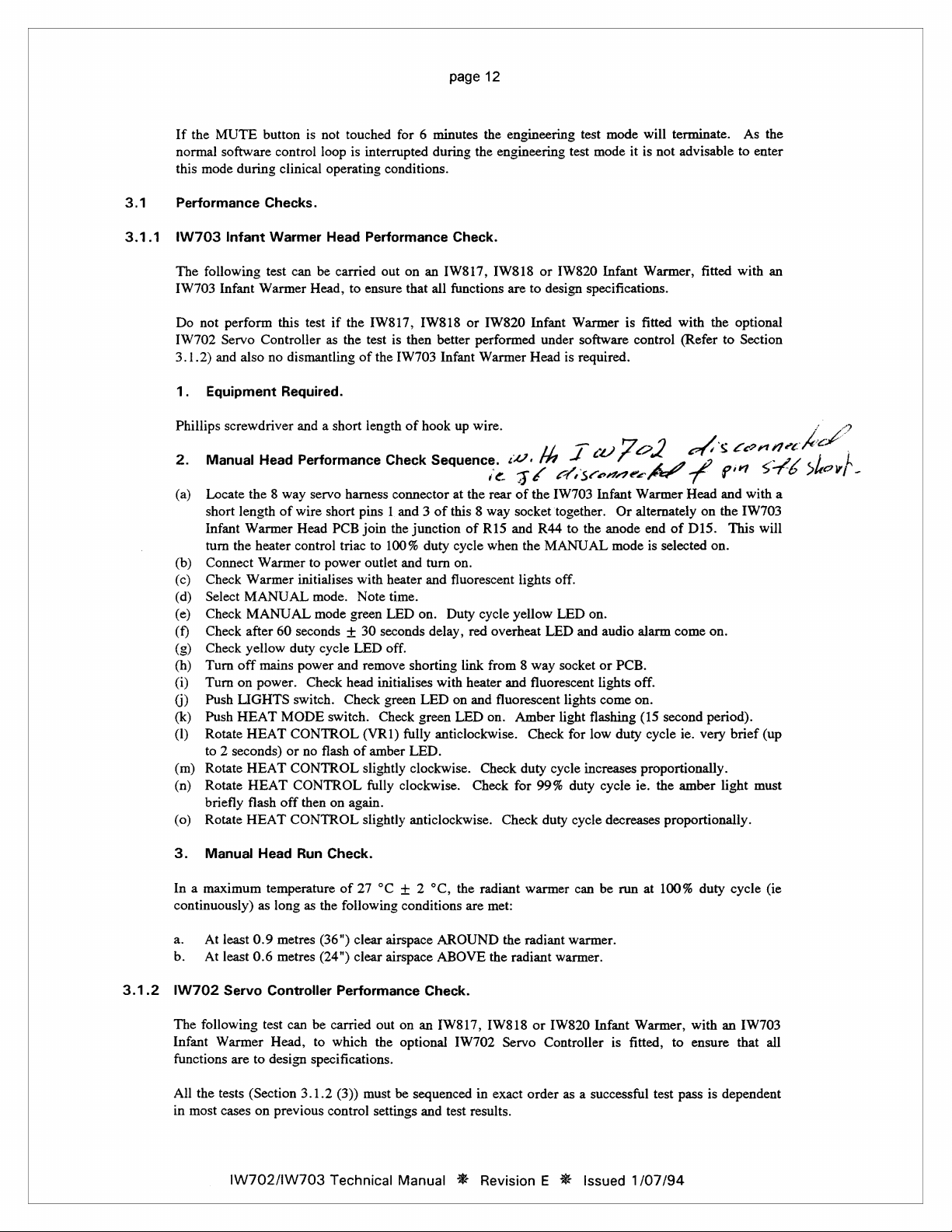
3.1
3.1.1
Performance
IW703
The
IW703
Do
IW702
3.1.2)
1.
Phillips
2.
(a)
(b)
(ο)
(d)
(e)
(5)
(h)
(i)
0)
(k)
(1)
(m)
(n)
(o)
Infant
following
Infant
not
perform
Servo
and
Equipment
screwdriver
Manual
Locate
short
Infant
turn
the
Connect
Check
Select
Check
Check
Check
Turn
Turn
Push
Push
Rotate
to 2 seconds)
Rotate
Rotate
briefly
Rotate
Checks.
Warmer
test
Warmer
Controller
also
no
Head
the 8 way
length
Warmer
heater
Warmer
Warmer
MANUAL
MANUAL
after
60
yellow
off
mains
on
power.
LIGHTS
HEAT
HEAT
HEAT
HEAT
flash
HEAT
Head
can
be
carried
Head,
this
test
if
as
dismantling
Required.
and a short
Performance
servo
of
wire
short
Head
PCB
control
triac
to
power
initialises
mode.
mode
seconds + 30
duty
cycle
power
and
Check
switch.
MODE
off
switch.
CONTROL
or
no
flash
CONTROL
CONTROL
then
CONTROL
on
Performance
out
on
to
ensure
that
the
IW817,
the
test
is
then
of
the
[W703
length
of
Check
harness
Check
connector
pins 1 and 3 of
join
the
junction
to
100%
outlet
and
with
heater
Note
time.
green
LED
seconds
LED
off.
remove
head
of
again.
slightly
shorting
initialises
green
Check
(VR1)
fully
amber
LED.
slightly
clockwise.
fully
clockwise.
anticlockwise.
Check.
an
[W817,
all
IW818
better
Infant
hook
Sequence.
duty
turn
and
on.
Duty
delay,
with
LED
green
anticlockwise.
[W818
functions
or
IW820
performed
Warmer
up
wire.
i
at
the
rear
this 8 way
of
R15
cycle
when
on.
fluorescent
cycle
red
overheat
link
from 8 way
heater
on
and
fluorescent
LED
on.
Check
Check
or
are
to
Infant
under
Head
^
<<:
TC
of
the
socket
and
R44
the
lights
yellow
and
fluorescent
Amber
Check
duty
for
99%
Check
[W820
Infant
design
specifications.
Warmer
software
ts
required.
с:
1
ce)
4
scones
A
IW703
Infant
together. Or
to
the
MANUAL
off.
LED
on.
LED
and
audio
socket
or
lights
lights
come
light
flashing
for
low
cycle
increases
duty
cycle
duty
cycle
Warmer,
is
fitted
control
À
©
A
il)
Warmer
alternately
anode
end
mode
is
selected
alarm
PCB.
off.
on.
(15
second
duty
cycle
proportionally.
ie.
the
decreases
proportionally.
with
(Refer
A
Á
Head
of
D15.
come
ie.
amber
fitted
with
the
optional
to
Section
(ег
$
a
pır
and
on
the
IW703
This
on.
on.
period).
very
brief
light
SA
with
will
(up
must
an
nec
a
ン
6
i
he
/
|
Shovi
o
2
人
-
3.
Manual
In a maximum
continuously)
a.
At
b.
At
3.1.2
IW702
The
following
Infant
functions
All the
in
most
Head
temperature
as
least
0.9
least
0.6
Servo
Controller
test
Warmer
tests
cases
Head,
are
to
design
(Section
on
1W702/1W703
Run
long
as
metres
metres
can
3.1.2
previous
Check.
of
27
°C + 2
the
following
(36")
clear
(24")
clear
Performance
be
carried
to
which
specifications.
(3))
control
Technical
conditions
airspace
airspace
out
on
the
optional
must
be
settings
Manual
°C,
the
AROUND
ABOVE
Check.
an
[W817,
[W702
sequenced
and
test
*
radiant
warmer
are
met:
the
radiant
the
radiant
[W818
Servo
in
exact
order
results.
Revision E X
can
warmer.
warmer.
or
IW820
Controller
as a successful
Issued
be
run
Infant
is
at
100%
Warmer,
fitted,
test
1/07/94
to
pass
duty
with
ensure
is
dependent
cycle
an
that
(ie
[W703
all
Page 17

page
13
1.
Equipment
34.5
°C
Test
The
34.5 °C
equivalent
Servo
2.
Ensure
(a)
Plug
(b)
(c)
(a)
(b)
(c)
(d)
(e)
(f)
(g)
(h)
(1)
0)
(k)
(1)
(m)
(n)
(0)
(p)
(q)
(r)
(s)
(t)
(u)
(v)
(w)
(x)
(y)
(2)
34.5
Turn
Servo
Turn
Observe
reads
On
IW703
On
IW702
Check
Turn
Check
Warmer
Turn
Check
Check
Display
alignment
Enter
Enter
Push
Ensure
and
enter
Wait
Momentarily
(Q17
Return
Push
Ensure
Test
Probe.
On
IW703
Check
Turn
On
IW703
Remove
Infant
Now
IW702
on
IW702
IW702
TEST
for
test).
TEST
IW702
go
Required.
Probe.
Test
Probe
is a bantam
to a temperature
Controller
IW703
°C
Controller
the
count
approximately
Infant
Servo
there
IW702
Head - Check
low
temperature
operation
temperature
with
engineering
engineering
button
IW702
engineering
audio
to
normal
button
[W702
Infant
MANUAL
Infant
34.5
Warmer
to
Section
Test
Infant
Warmer
Test
Probe
Servo
Controller
Performance
IW703
Infant
up
on
IW702
34.5.
Warmer
Controller - Check
is
no
audio
Servo
Controller
Servo
Servo
Controller
of
MUTE
control
front
panel
menu
test
and
Servo
Controller
test
alarm
at
push
the
operation
and
Servo
Controller
Warmer
mode
Servo
Controller
Warmer
°C
Test
Head - Check
3.1.1
phone
of
34.5
°C.
Set-up.
Head
into
IW702
temperature
Warmer
Servo
Head - Check
alarm
or
alarm
temperature
Controller
yellow
alarm
(Refer
menu
check
safety
MUTE
check
LED
Probe - Push
(2)
high
duty
temperature
LED
button
(Alarm
setting
calibration
to
Section
number A (Refer
display
temperature
b.
relay
button
(engineering
display
temperature
Head
select
on
IW702
temperature
Head - Check
MANUAL
and
perform
plug
with
HEAT
CONTROL
Servo
Controller.
control
Check
Sequence.
Head.
Controller.
SERVO
SERVO
cycle
and
shows
time
reads
the
mode
LED's.
control
temperature
LED
control
audio
on.
Mute).
(Refer
to
(34,
36
degrees).
3.0.2).
to
horizontal
control!
out (30
and
check
test
F).
38.0 + 0.2
control
MANUAL
Servo
control
MANUAL
MUTE - Check
mode
tests
(1)
two
1500
Ohm
turned
fully
clockwise
Check
all
green
LED
green
fully
anticlockwise
alarm
off.
fully
clockwise
Section
Section
to
Remove
Controller
LED
Check
bars
fully
90
seconds
for
safety
degree
fully
CONTROL.
fully
anticlockwise
mode
on,
to
(o)
on
3.0.1).
software
3.0.3).
display
duty
1%
resistors
fully
(37).
LED's
flash
on.
LED
on.
LED
and
(37).
Check
version
(if
not
Refer
clockwise.
indicated
relay
reset
34.5
°C
Test
(mute
clockwise
is
on.
LED
off,
blanks - no
cycle
LED
the
[W703
wired
clockwise.
alarm
(32).
audio
on.
temperature
at
number
to
Section
Plug
|
on
display).
and audio
Probe.
alarms
if
(37)
and
(32) - check
duty
cycle
alarms.
on.
Infant
Warmer
in
circuit.
beeps.
Check
On
IW703
control
2.
3.2).
in
34.5
°C
alarm
desired).
plug
in
high
LED
off
On
Head.
display
Test
cessation
the
34.5
alarm.
(016
the
[W703
This
is
Infant
knob
Probe
°C
test).
IW702/1W703
Technical
Manual # Revision E #
Issued
1/07/94
Page 18

page
14
3.2
3.2.1
IW702
There
Refer
carried
to a horizontal
On
display
transition.
38 °C
(a)
(b)
(с)
(d)
Servo
is
only
one
to
Sections
out
and
bar
accomplishing
and
again
Over
Temperature
Enter
engineering
Push
the
Servo
'A|
|||"
Back
off
VR3
Exit
through
to
indicate
Controller
temperature
1.7
set
exactly.
display.
this
adjust
to
slightly
engineering
38.0 + 0.2°C
Calibration.
and
2.3.2.)
transition,
for
test A (Refer
TEST
button
horizontal
to
calibration
The
correct
the
Protection
'A==".
return
test F and
approximately 1 second
adjustment
This
is a critical
setting
back
the
horizontal
Calibration.
to
Sections
and
adjust
to
the
vertical
check
point
control
display
3.0.1 - 3.0.3).
VR3
that
to
perform.
adjustment
is
where
(VR3)
to
ensure
so
the
display
display
the
displayed
after
related
the
off
slightly
that
just
'A|
| |
|'
message
pushing
(38
°C
display
the
changes
and
TEST
Over
Temperature
to
patient
just
changes
to
return
adjustment
from
repeat
step
'Prb'
changes
button.
safety
and
from a vertical
to
the
vertical
in
on
the
vertical
bars
b.
through
Protection.
must
be
bar
point
of
'---'
IW702/IW703
Technical
Manual
#
Revision E #
Issued
1/07/94
Page 19

page
15
4.0
Servicing
During
window
and
stop
the
count
than
256
indicated.
While
operating
present
maintain
Some
of
with
an
Error
Code
Ec
En
b-1
*|
b-2
*|
EXx
Prb | Temperature
E20 | Twin
E30 | Failure
E31 | Failure
E32 | Incorrect
Information.
operation
an
of
exceeding
an
on
pin 3 of
the
explanation
Failure
Toggling.
Checksum
Memory
Mute
Test
(only
|.
Where X = O through
multiplexer
Where x = 0 or
overflow
Or,
8000
within
test.
Or,
Calibration.
if
the
microprocessor
error
condition
the
integration
certain
underflow
pins 8 and 9 of
error
to
button
button
if
skin
thermistor
Ohms.
probe
2%
of
of
open
error
normally a square
U2-A
low.
indications
of
the
possible
Explanation
establish
error.
test
error.
stuck
stuck
down.
sensor
stage
where
u,
error
or
underflow
sensor
resistance
mismatch. Thermistors
tolerance.
isolation
isolation
circuit
in
Analog
38
will
be
flagged.
ramp
from
limits
generate
is
generated
wave
Ul-C.
automatic
down.
not
indicating
not
relay
relay
heater
°C
which
cause,
plugged
7,
indicating
error
plugged
not
drop
to
reset
circuit.
Overtemp
This
can
error.
U3
does
U14-A
an
and
of
the
be
displayed
and
Watch
in)
occurred.
ADC
in.
between
not
out
self
after
not
receive
an
expected
In
particular
and
error
should
the
Watch
corrective
Dog
200 ~ |
test. | Check
self | Check
also
controls
message.
the
same
period
Dog
on
Check
Toggling
Check
Check
Free
Free
See
Plug
Check
between
Clean
jack
thermistor
if
after
Check
Section
approx.
Check
Section
Check
Check
Section
the
RST
the
When
count
as
Toggling
the
[W702
actions.
for
signal.
possible
possible
or
replace
or
replace
Explanation.
in
Temperature
thermistor
200 ~ 8000
jack
socket,
E20
still
for
approx
38
°C
3.2.1.)
for
55
38
°C
3.2.1.)
elements
calibration
3.2.1.)
interrupt
6.5
interrupt
counter
the
count
exceed
the
Watch
plug,
resistance
exists,
1solation
isolation
seconds
16128
mains
signal,
Servo
Action
Dog
failure
failure
SW2.
SW1.
resistance
check
check
thermistor
discard probe.
relay
55
seconds
Overtemp
relay
from
Overtemp
for
open
of
within a given
which
in
U6
will
recorded
an
overflow
power
supply
sourced from
Controller
Clock
and
of
U5
EPROM.
of
U6
RAM.
Sensor.
for
Ohms.
for
faulty
resistances.
not
within
dropout
from
initial
Calibration.
RL]
reset
initial
Calibration.
circuit.
38
°C
Overtemp.
marks
in
the
by
U6
U6,
are
listed
Watch
each
bead
contacts
2%
tolerance
prior
power
(Refer
after
power
(Refer
If
so,
time
the
start
event
is
error
should
should
below,
Dog
in
If
to
reset
on.
on.
replace.
(Refer
of
less
is
be
or
*
These
error
codes
IW702/IW703
refer
to
the
version
Technical
2.5
software
Manual
only.
*
Revision E #
Issued
1/07/94
Page 20

page
16
Other
Error
Conditions:
If
the
display
remains
crashed
If
optoisolators
If
IW702
or
during
on
pushing
Servo
failed
the
U8,
Controller
to
initialise.
start
routine,
U9
the
TEST
blank
and
Check
the
and
U16.
button a 'Prb'
PCB
(Refer
only
the
for
display
error
to
Section
high
temperature
Watch
fails
to
continues
Dog
count
3.2).
red
Toggling
past
to
display,
LED
is
signal.
'000',
check
check
on,
then
the
Check
status
isolation
calibration
microprocessor
of
EPROM.
power
supply
of
VR3
on
rear
has
or
of
4.1
4.2
Option
A
back
*
Overheat
The
100%
be
To
commences
uncontrolled
45
Selection.
number
of
the
Options
PCO
PCI
PC2
PC3
PC4
PCS
These
options
OVERHEAT
duty
silenced
determine
to
75
seconds
of
operational
Servo
Controller
Pads
Open
ISO
Draft
30
min.
monitor
Manual
Single
N/A
refer
Alarm.
ALARM
cycle
or
the
by
turning
which
immediately
duty
cycle
after
functions
PCB.
Standard
warm
mode.
alarm.*
Thermistor
to
version
on
operation
the
[W703
fault
caused
it
is
of
the
switch
on.
can
Alarm.
up
in
servo/man-
No
Unmonitored
Temperature
2.5
software
the
[W703
of
the
Infant
the
the
overheat
warmer
be
optionally
only.
Infant
mechanical
Warmer
alarm,
if
protector
head
then
selected
Sensor.
Warmer
overheat
Head
the
power
the
alarm
Pads
Continuous
Twin
Head
power
is
which
will
by
linking
Joined
15
min
warm
15
min
unconditional
Manual
alarm.*
Probe
is
enabled
protector
switch
off.
again
turned
has
open
not
be
the
pads
of
gliding
audio
up.(servo/man
Unmonitored
(Two
thermistors
either
by
H1.
The
audio
on
and
circuited.
enabled
before a delay
Port
alarm
the
the
If
the
PCO - 5
tone.
monitor
sensor).
detection
alarm
can
overheat
fault
of
on
the
only)
of
only
alarm
is
the
about
a
The
overheat
the
[W703
key
is
before
Before
such
as
heaters.
protector
Infant
ideal
and
attempting
resetting,
restricted
IW702/IW703
Warmer
using a moderate
to
reset.
the
1W703
ventilation
reset
mechanism
Head
Infant
Technical
radiant
of
the
is
heater.
upward
Warmer
[W703
Manual
accessible
It
can
pressure.
Head
should
Infant
Warmer
X
Revision E %*
through
be
reset
Allow
be
the
small
by
inserting a thin
at
least 5 minutes
examined
Head
or
noticeable
Issued
hole
for
about
some
1/07/94
50
mm
shaft, a 2
for
the
cause
damage
of
to
head
the
to
the
the
mm
rear
of
Allen
to
cool
overheat,
radiant
Page 21

page
1/
4.3
Skin
Temperature
If
using a twin
should
be
Although
conductors
the
thermistor
If
the
skin
been
handled,
sensor
together
between
resistance
following
Where
ambient
Measure
Measure
Measure
Thenx = y
R =
Sensor
thermistor
carried
out
the
processor
in
the
sensor
beads.
sensor
has
use
an
with
the
and
using
the
chart
resistances.
Path A -
Path B -
Path A - B =
=2/2=R
resistance
NN
Test
temperature
every
three
program
cable
been
at
accurate
thermometer
40
°C.
over.
C =
C =
at
the
thermometer
(Probe).
months
checks
are
shorted
ambient
thermometer
From
Now
x
y
2
sensor
identifiable
to
check
for
equal
circuit
to
one
another
temperature
may
the
using a digital
(tolerance < 2%)
temperature
for
to
determine
be
placed
thermometer
by a blue
for
internal
paths
it
or
if
there
at
least
10
the
ambient
in a container
reading
Ohm
meter
(refer
to
Section
connector
shorts
in
does
not
are
symmetrical
minutes
temperature.
of
warm
determine
(0 - 10000
4.4).
C
plug,
the
sensor
determine
and
the
water
the
correct
Ohms
A
the
following
head
or
cable.
if
the
individual
partial
shorts
sensor
end
has not
Alternately
at a temperature
skin
sensor
range)
note
test
of
the
the
4.4
Probe
Temperature
ANA
versus
Temperature
(°C)
20
21
22
23
24
25
26
27
28
29
Thermistor
Resistance
(Ohms)
2812.8
2688.9
2571.8
2459.2
2353.3
2250.0
2155.8
2064.4
1976.6
1893.3
Resistance.
Temperature
(°C)
30
31
32
33
34
35
36
37
38
39
B
Resistance
(Ohms)
1814.4
1739.2
1667.2
1598.2
1532.9
1470.6
1411.3
1355.0
1301.0
1249.2
IW702/IW703
Technical
Manual
№
Revision E %
issued
1/07/94
Page 22

page
4.5
[W703
Infant
Warmer
Head
Circuit
Diagram
043
18:
040
571.
<
cus
wurst
IW702/IW703
Technical
Manual # Revision E *
Issued
1/07/94
ΜΗ
ONTRMEM
PROTECRA
(100)
VEL
&
DIVISION
ELECTRONICS
PAYKEL
L
Page 23

page
19
4.6
IW702
Servo
Controller
Circuit
Diagram
043
040
567
Sheet
1.
017
1N4002
DIS
1N4002
U7
MMS451
sop
o!
BC5478
UID
74HC02
10UF
10uF
TP2
ov
+5\
/16V
144148
1N4148.
D1
1N4148
D
4
D3
144148
74HC132N
920
74HC132N
U2E
74HC132N
2
=
Cit
/16v
+
1
I;
v
G
d
+»
や
о
i
v
о
tn
D8
D7
SERVO | POP
D29
i
<=
o
“J
C1
22PF
U3
8085АН--2
y
A[08:15]
CTRL{00:04]
S.
DRAWN
SURTEES
00NF
C4
AD{
00:07)
ua
74LS373
U2C
74HC132N
7
HEALTHCARE
FISHER & PAYKEL
25
CARBINE
RD,
P.O.
BOX
14-348
AUCKLAND,
NEW
PH
(649)
570-5655
DRAWING
043
040
PANMURE.
PANMURE,
ZEALAND.
FAX
NUMBER
567
102
DIVISION
ELECTRONICS
(649)
570-9500
U1C
Q16
BC5478
Q2
805478
TELEX
DUTY
/RESET
MAN
/SERVO
/OVERTEMP
SERVO
LED
RIAC
CNTAL
J7-4
i
ov
LTD
NZ2995
SHEET
1
OF
2
IW702/IW703
Technical
Manual # Revision E %
Issued
1/07/94
Page 24

Page 25

Page 26

Page 27

Page 28

Page 29

Page 30

page
24
5.0
5.1
Spare
IW703
Ref.
l
2
3
4
5
6
7
8
9
10
11
12
13
Parts
Infant
Description
Lamp-14V
LensBlue
Fuse5A20x5mmguickacting(for230V)...........................................
Fusel0A420x5mmnfastacting(forll5V).............................................
Transformer
Transformer
PCBAssembiyIW703Complete230V..............................................
PCBAssembiyIW703Completell5V.....................................
Lamp
ReflectorandHeaterAssembiy230V
Reflector
Cover
Knob
Mains
Mains
Mains
Plug
Cable
ClipRetainer.....................................
Fuse1A20xSmm
Lists.
Warmer
Fluorescent
Light
Moulded
Power
Power
Power
Mains
Grip
Head - Spare
.4
AssemblyIW703230V
AssemblyIW703
and
Heater
.se
Control.............................
CordIW703
CordIW703
Cord
3-Pin
Type...
P
-
18W
Assembly
IW703
Clear
.ee
Grey
230VNZ/Aust.............
115V
Free
Top
models
Parts / Exploded
λνκκε
εκ
heh
06
eee
eee
eee
.Ne
113V
...................................................
120V
iii
i
eee
(no
plug)........................
eee
ss
иене,
Diagram.
ολκνε
κκ
καλα
ri
κνλλλλλ
εαν
eee
eee
nete
nene
κε
een
teké
ne
κλαν
e
Part
424040049
424040042
348060013
999830011
043040551
043040552
043040571
043040610
424040055
ee
648040089
648040100
693040380
693040285
095428128
095428208
095428248
341040434
647040117
625060013
999830001
No.
Lexan
233201392
233201443
(Eng)
(Spa)
IW702/1W703
Technical
Manual # Revision E #
Issued
1/07/94
Page 31

Page 32

page
25
5.2
IW702
Ref.
EM
&
Ch
Servo
Controller - Spare
Description
Fuse
lA
20XS5Smm
SkinSensorProbe
ScrewM6x10(AllenS/S).................................
Knob
Moulded
PCB
AssembiyIW702ZAEU
ο»
Control
/
q
Parts / Exploded
..................................................
ServolComplete
ds
一
Diagram.
................................
1o
ο
一
ses
一
ee n ee
0
0.000
serra
en
|
ον
ont}
=$
Part
No.
99983000
8001
614040254
693040285
043040846
1
W007
3
Cr
ュー
|
SERVO
WTO2
¿Poy
E
F
ους
>
ή,
U
эм
“YY:
x
TEMPERATURE
CONTRO,
스
—
ar
CONTROLLER
L
<
wo =
MODA
=
or
0 A tae
SS
ee,
‘See.
PET
00
na a HO
dh
Ὁ
ποσα
er
a
о
o
at
—
|
Lexan
233201393
IW702/IW703
Technical
Manual * Revision E *
Issued
1/07/94
Page 33

Page 34

page
26
IW817
Ref.
]
2
3
4
5
6
7
8
9
10
11
Infant
Radiant
Description
CastOT
Plus
Kectangujar
ScreewM6oXxiI2(AllenS/S)
Saddle
12mm
Screw
M4
SaddleYS..............................
Screw
M4 X 12
KnobClamp
Screw
M4X6
Screw
M6 X 10
Inmfant
Warmer
Warmer - Spare
Light
GreV
X25
ooooooocccccococcconcnccncconno
.........................................».
esasen
(Allen
S/S)
Head
Parts / Exploded
................................
rc
0 0 K 0 S R K K K
déesse
rro
no
raro
Diagram.
ses
esse
eee
esse
rcnc
ano
ronnccccanarocoro
esse
ss.
n
se.
esasen
нени
нь
Part
No.
665040007
693040615
614040255
647040115
614040193
647040114
614040195
651040144
614040194
614040254
se
IW703
1W702/1W703
Technical
Manual # Revision E #
Issued
1/07/94
Page 35

Page 36

Page 37

Page 38

page
28
5.5
iW820
Infant
©
000
©
d0e00
000000
Care
Centre - Exploded
Diagram.
|
a
НЯ
V
M
a
19
©
|
VU
e
|
VD
nů
Wi
IW702/IW703
Technical
Manual
#
Revision
E
#
Issued
1/07/94
Page 39

Page 40

page
29
6.0
6.1
Spare
IW703
Ref.
1
3
4
5
6
7
8
9
10
11
12
Parts
Infant
Description
Lamp - 14V
lensBlue........................................
Fuse5A420X5mmguickacting(f0r230V)...................................
Fuse
Transformer
Transformer
PCB
PCBAssembiyIW703
Starter
Lamp
RefletorandHeater
Reflector
Coverlight........................................
Knob
Lists.
Warmer
10A
20x
Assembly
Light
Fluorescent
and
Moulded
Blue
models
Head - Spare
5mm
fast
AssembiyIW703230V.......................................
AssembiyIW703115V.....................................
!W703
Complete
Complete
230V
13W
18W
Assembiy230V
Heater
Assembly
Control......................
Parts / Exploded
000000000
acting
(for
115V)
...................
230V . 2 2 0
1l5V....................................
.................................
.....................................
115V
..........
P
enes
eee
2...
erre
Diagram.
이니 이 다 이 워 이
erre
eee
eee
Lc
res
ee
미 이 이 이
esset
se
ken
348060013
999830011
043040551
043040552
이
043040571
043040610
999890022
693040380
693040285
095428099
999830001
IW702/IW703
Technical
Manual * Revision E *
Issued
1/07/94
Page 41

Page 42

page
30
6.2
IW702
Ref.
+
WN
N
Servo
Controller - Spare
Description
Fuse
IA
20X5mm
Skin
Sensor
Probe
ScrewM6Xx10(AllenBlack).................................
Knob
PCB
Moulded
Assembly
Control
IW702
eee
Servo
Parts / Exploded
Controller
Complete...........................
Diagram.
eee
ee
nan
Part
999830001
8001W007
614040175
693040285
043040567
ω
4
b
No.
一
一 @
IW702/IW703
Technical
Manual % Revision E #
Issued
1/07/94
Page 43

Page 44

page
31
6.3
1W817
Ref.
Infant
Radiant
Description
Plug
Rectangular
Screw
M6 x 12
Saddle
12mm
se
Knob
Clamp
Screw
M4x6
Screw
M6 x 10
Infant
Warmer
Warmer - Spare
Black
Arın
sas
Mk...
$
ee
OAK.
(Allen
Black)
MA
Head
ооо
Parts / Exploded
o...
-PH
ооо
........
s.a.
eee
ii...
оао
ei...”
OŘ
eee
AAA...
ооо
Diagram.
Part
No.
IE...
оо
ооо
ооо
ооо
NEE
E
ACC
ооо
A
E a a
осо
aa
nu
693040393
l
614040188
647040115
614040193
647040114
614040195
à
651040144
614040194
dd
11
IW702/IW703
Technical
Manual
*
Revision
E
*
Issued
1/07/94
Page 45

Page 46

Page 47

Page 48

page
33
6.6
IW818
Infant
Resuscitation
Centre - Exploded
Diagram.
4
©
©
1
IL
(©
q
A
=)
ザー
y
e
А
-
un
3
©
©
IW702/IW703
Technical
Manual
**
Revision
E
*
Issued
1/07/94
Page 49

Page 50

page
34
6.7
IW820
Infant
Intensive
Care
Centre
-
Exploded
Diagram.
IW702/1W703
Technical
Manual
#
Revision
E
#
Issued
1/07/94
Page 51

Page 52

page
35
7.0
Product
This
change
changes.
Date
25/01/91
22/04/92
22/09/93
30/11/93
8/12/93
24/2/94
Change
history
details
Refer
also
to
change
Change
Number
0608
0986
1697
1807
1824
1895
First
91LA0001
92KA0078
|
9302AEU00071
9303JEU00111
93LA0182
9303
AEA00127
94LC0001
9303JEU00079
History.
changes
panel
serial
number
affected
|
|
|
which
may
have
significance
on
circuit
diagrams.
Model
IW703A
IW702A
|
IW702AEU
IW703JEU
IW703A
IW703AEA
IW703J
IW703JEU
|
Replaced
118°C.
|
Introduction
Features:
Error
relay
incorrect
Addition
successful
servo
Amendment
during
Amendment
Button
|
Change
Introduction
Features:
Unconditional
alarm
plus
indicate
Warm
minutes
warmup
alarm
Addition
during
gives
Amendment
selection
Manual
|
Resistor
|
Change
DA
250%.
Add
resistor
to
[W703
for
servicing.
thermostat
of
Version
message
test
analog
selection
38
and
colour
while
12
minute
imminent
up
(was
and
via
programming
initialisation.
'b-1'
of
mode
R31
fuses Fl
J
routine.
38
of
short
button
buttons.
to
°C
Overtemp
to
38
Exit.
from
of
Version
15
in
unmonitored
intermittent
time
in
30
minutes).
no
unmonitored
of
error
and
stuck
to
initialisation
Manual
during
changed
and
R47
(18092)
models
'E32'
latching
shutdown.
Manual/Servo
only.
It
does
Comments
93°C
(H1)
2.4
Software.
added
This
error
directly
°C
overtemp
audio
pulse
for
Engineering
Calibration
°C
Test
Routine
blue
to
grey.
2.5
Software.
minute
codes
TEST
Monitor
the
from
F2.
Optional
port
PC1.
for
A
stuck
button
routine.
10kQ
Were
capacitor
MANUAL
MANUAL
warning
MANUAL
routine
or
not
include
with
thermostat
to
the
isolation
indicates
calibration.
to
indicate
IW703
‘stuck'
MUTE
Test
and
via
beep
modes
30
gives
to
Unmonitored
to
820Q.
SA
125V
C16
(100nF)
manual/
Routine
Exit.
mode
mode
now
minute
mode
buttons
button
'b-2'.
enable
now
all
Test
to
15
IW702/1W703
Technical
Manual
*
Revision
E
%№
Issued
1/07/94
Page 53

page
36
7.1
Serial
8
Model
KA
12
digit
LA
LB
LC
digit
Number
format
IW703A
IW703Z
IW703J
IW702A
format
Explanation.
YEAR
Country
YEAR
MODEL
\
92
\
93
|
AA
Australia/Europe
NZ
USA
Australia/Europe
MODEL
XX
XXXX
CODE
| |
UNIT
ААА
/
NUMBER
Volts
230V
230V
115V
10V
SERIAL
XXXXX
NUMBER
/
Model
Number
THREE
First
A
02
03
17
20
J
Model
[W702
IW703
[W817
[W820
LETTER
Letter
|
Voltage
230V + 20V
115V + 15V
Type
CODE
|
Second
E
Letter
Front
English
Panel
Language
|
Third
A
K
U
V
Letter
Customer
Australasian
as
per U but
Universal
Wall
Mounted
CKD
1W702/1W703
Technical
Manual
*
Revision E *
Issued
1/07/94
 Loading...