

Site Considerations for Equipment Installation, Grounding, and Wiring Manual
D301452X012
October 2019
Remote Automation Solutions
Site Considerations for Equipment
Installation, Grounding, and Wiring
Manual
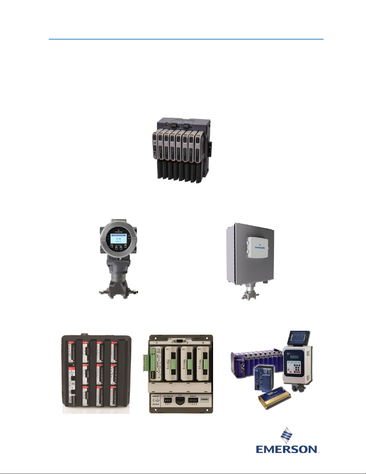
FB3000 Remote Terminal Unit (RTU)
FB1100/1200 Flow Computer FB2100/2200 Flow Computer
ROC800, FloBoss™107, ControlWave™ Family of Flow Computers and RTUs

Site Considerations for Equipment Installation, Grounding, and Wiring Manual
D301452X012
October 2019
ii
Device Safety Considerations
▪ Reading these Instructions
Before operating the device, read these instructions carefully and understand their safety implications.
In some situations, improperly using this device may result in damage or injury. Keep this manual in a
convenient location for future reference. Note that these instructions may not cover all details or
variations in equipment or cover every possible situation regarding installation, operation, or
maintenance. Should problems arise that are not covered sufficiently in the text, immediately contact
Customer Support for further information.
▪ Protecting Operating Processes
A failure of this device – for whatever reason -- may leave an operating process without appropriate
protection and could result in possible damage to property or injury to persons. To protect against
this, you should review the need for additional backup equipment or provide alternate means of
protection (such as alarm devices, output limiting, fail-safe valves, relief valves, emergency shutoffs,
emergency switches, etc.). Contact Remote Automation Solutions for additional information.
▪ Returning Equipment
If you need to return any equipment to Remote Automation Solutions, it is your responsibility to
ensure that the equipment has been cleaned to safe levels, as defined and/or determined by applicable
federal, state and/or local law regulations or codes. You also agree to indemnify Remote Automation
Solutions and hold Remote Automation Solutions harmless from any liability or damage which Remote
Automation Solutions may incur or suffer due to your failure to ensure device cleanliness.
▪ Grounding Equipment
Ground metal enclosures and exposed metal parts of electrical instruments in accordance with OSHA
rules and regulations as specified in Design Safety Standards for Electrical Systems, 29 CFR, Part 1910,
Subpart S, dated: April 16, 1981 (OSHA rulings are in agreement with the National Electrical Code).
You must also ground mechanical or pneumatic instruments that include electrically operated devices
such as lights, switches, relays, alarms, or chart drives.
Important: Complying with the codes and regulations of authorities having jurisdiction is essential to
ensuring personnel safety. The guidelines and recommendations in this manual are intended to meet
or exceed applicable codes and regulations. If differences occur between this manual and the codes
and regulations of authorities having jurisdiction, those codes and regulations must take precedence.
▪ Protecting from Electrostatic Discharge (ESD)
This device contains sensitive electronic components which can be damaged by exposure to an ESD
voltage. Depending on the magnitude and duration of the ESD, it can result in erratic operation or
complete failure of the equipment. Ensure that you correctly care for and handle ESD-sensitive
components.
System Training
A well-trained workforce is critical to the success of your operation. Knowing how to correctly install,
configure, program, calibrate, and trouble-shoot your Emerson equipment provides your engineers and
technicians with the skills and confidence to optimize your investment. Remote Automation Solutions
offers a variety of ways for your personnel to acquire essential system expertise. Our full-time professional
instructors can conduct classroom training at several of our corporate offices, at your site, or even at your
regional Emerson office. You can also receive the same quality training via our live, interactive Emerson
Virtual Classroom and save on travel costs. For our complete schedule and further information, contact the
Remote Automation Solutions Training Department at 800-338-8158 or email us at
education@emerson.com.

Site Considerations for Equipment Installation, Grounding, and Wiring Manual
D301452X012
October 2019
iii
Contents
Section 1: Overview 1
1.1 Safety Labels ......................................................................................................................... 1
1.2 Major Topics ......................................................................................................................... 2
Section 2: Protection 3
2.1 Protecting Equipment Systems ............................................................................................. 3
2.1.1 Quality is Conformance to Requirements ................................................................... 3
2.2 Protecting Equipment and Personnel .................................................................................... 3
2.2.1 Considerations for Protecting Personnel .................................................................... 4
2.2.2 Considerations for Protecting Equipment .................................................................. 4
2.3 Other Site Safety Considerations ........................................................................................... 5
Section 3: Grounding and Isolation 7
3.1 Power and Ground Systems .................................................................................................. 7
3.2 Importance of Good Grounds ................................................................................................ 7
3.3 Earth Ground Connections .................................................................................................... 7
3.3.1 Establishing a Good Earth Ground .............................................................................. 8
3.3.2 Ground Wire Considerations .................................................................................... 11
3.3.3 Other Grounding Considerations ............................................................................. 12
3.4 Isolating Equipment from the Pipeline ................................................................................ 13
3.4.1 Meter Runs without Cathodic Protection ................................................................. 13
3.4.2 Meter Runs with Cathodic Protection ....................................................................... 14
Section 4: Lightning Arresters and Surge Protectors 17
4.1 Strike .................................................................................................................................. 17
4.1.1 Chance of Being Struck by Lightning ........................................................................ 17
4.1.2 Antenna Caution ..................................................................................................... 20
4.1.3 Ground Propagation ................................................................................................ 22
4.1.4 Tying it all Together ................................................................................................. 22
4.1.5 Impulse Protection Summary .................................................................................. 22
4.2 Use of Lightning Arresters and Surge Protectors .................................................................. 23
4.2.1 Installing Lightning Arresters and Surge Protectors .................................................. 23
Section 5: Wiring Techniques 27
5.1 Overview ............................................................................................................................ 27
5.2 Device Wiring ..................................................................................................................... 27
5.2.1 Avoid Common Returns ........................................................................................... 27
5.2.2 Use Twisted Shielded Pair Wiring (with Overall Insulation) ....................................... 28
5.2.3 Ground Cable Shields ............................................................................................... 28
5.2.4 Use Known Good Earth Grounds .............................................................................. 29
5.2.5 Earth-ground Wires ................................................................................................. 29
5.2.6 Work Neatly and Professionally ................................................................................ 29

Site Considerations for Equipment Installation, Grounding, and Wiring Manual
D301452X012
October 2019
iv
5.2.7 Observe High Power Conductors and Signal Warning .............................................. 29
5.2.8 Use Proper Wire Size ................................................................................................ 29
5.2.9 Use Lightning Arresters & Surge Protectors .............................................................. 30
5.2.10 Secure Wiring Connections .................................................................................... 30
Section 6: Grounding and Bonding a Solar PV Array 33
6.1 Code Requirements ............................................................................................................ 33
6.2 Ground Attachment ............................................................................................................ 33
6.3 Non-Conductive Components ............................................................................................ 34
6.4 Non-Conductive Coatings ................................................................................................... 34
6.5 Grounding Method ............................................................................................................. 35
6.6 Corrosion Protection ........................................................................................................... 36
6.7 Lightning Protection Considerations ................................................................................... 36
Site Considerations for Equipment Installation, Grounding, and Wiring Manual
D301452X012
October 2019
Overview 1
Section 1: Overview
This section covers the following topics:
▪
Safety Labels
▪
Major Topics
This document provides information pertaining to the installation of RTUs, controllers, and flow
computers from Emerson Remote Automation Solutions, including the ROC, FloBoss devices,
FB1000 and FB2000 Series of flow computers and the FB3000 RTUs. More specifically, this
document provides information covering reasons, theory, and techniques for protecting your
personnel and equipment from electrical damage. Your system equipment affects both the quality
of service your company provides and many aspects of its operational safety. Loss of equipment
means lost production and profits as well as increased expenses.
Note
Information contained in this document is for educational purposes. Emerson Remote Automation
Solutions offers no warranties or guarantees on the effectiveness of the safety of techniques
described herein. Where the safety of installations and personnel is concerned, refer to the
National Electrical Code Rules and rules of local regulatory agencies.
1.1 Safety Labels
This product may display safety label(s) to identify potential hazards. The same types of notices
appear within the documentation. Whenever you see an exclamation point (!) enclosed within a
triangle (shown to the left), consult the documentation for additional safety information about the
hazard and how to avoid it. The labels used are:
DANGER
MAY CAUSE DEATH
Observe all precautionary signs posted on the equipment.
Failure to do so may result in death or serious injury to personnel.
WARNING
DANGER TO PERSONNEL AND EQUIPMENT
Observed all precautionary signs posted on the equipment.
Failure to do so may result in injury to personnel or cause damage to the equipment.

Site Considerations for Equipment Installation, Grounding, and Wiring Manual
D301452X012
October 2019
2 Overview
CAUTION
DANGER TO PERSONNEL AND EQUIPMENT
Observed all precautionary signs posted on the equipment.
Failure to do so may result in injury to personnel or cause damage to the equipment.
SAFETY FIRST
General instructions and safety reminders.
1.2 Major Topics
Topics are covered in five sections which are designed to pinpoint major areas of concern for the
protection of personnel and site equipment:
▪
Section 2 – Protection
This section provides the reasons for protecting equipment systems. It presents an overview
of the definition of quality, what we are trying to accomplish in the protection of site
installations, how to satisfy the defined requirements, and considerations for the protection
of personnel and equipment.
▪
Section 3 – Grounding & Isolation
This section provides information as to what constitutes a good earth ground, how to test
and establish such grounds, as well as when and how to connect equipment to earth
grounds.
▪
Section 4 – Lightning Arresters & Surge Protectors
This section presents technical and statistical information about lightning strikes, details how
to determine the likelihood of a lightning strike, discusses protecting equipment and
personnel during the installation of radios and antennas, and reviews the dangers to
personnel and equipment when working with antennas. Included is a discussion on using
lightning arresters and surge protectors along with overviews of how each device protects
site equipment.
▪
Section 5 – Wiring Techniques
This section covers installing power and “measurement & control” wiring; includes
information on unique situations, circulating ground and power loops, bad relays, and good
wire preparation and connection techniques. In addition to presenting problems to avoid,
this section lists ten rules of instrument wiring.
▪
Section 6 – Grounding and Bonding of Solar Photovoltaic (PV) Arrays
This section discusses grounding and bonding of solar PV arrays, and covers code
requirements, ground attachment, and grounding methods.

Site Considerations for Equipment Installation, Grounding, and Wiring Manual
D301452X012
October 2019
Installation 3
Section 2: Protection
This section covers the following topics:
▪
Protecting Equipment Systems
▪
Protecting Equipment and Personnel
▪
Other Site Safety Considerations
2.1 Protecting Equipment Systems
Electrical equipment is susceptible to damage from a variety of natural and man-made
phenomena. In addition to wind, rain and fire, the most common types of system and equipmentdamaging phenomena are lightning, power faults, communication surges, noise and other
electrical interference caused by devices such as radios, welders, switching gear, automobiles, etc.
Additionally, there are problems induced by geophysical electrical potential and noise plus things
that are often beyond our wildest imagination.
Quality is Conformance to Requirements
A quality equipment system is one that works reliably, safely and as purported by its manufacturer
(and in some cases by the system integrator) as a result of good equipment design and well defined
and followed installation practices. If we accept the general definition of quality as “conformance
to requirements,” we must also accept the premise that a condition of “quality” cannot exist where
requirements for such an end have not been evolved. In other words, you cannot have quality
unless you have requirements that have been followed. By understanding the requirements for a
safe, sound, and reliable equipment system, and by following good installation practices (as
associated with the personnel and equipment in question), you enhance the operational integrity
of the equipment and system.
Understanding the requirements for properly and safely installing equipment in various
environments in accordance with good grounding, isolating, and equipment protection practices is
fundamental for maintaining a system which is healthy for both the owner and customer.
Properly installed equipment is easier to maintain and operate and is more efficient and more
profitable to our customers. Following good installation practices minimizes injury, equipment
failure, and customer frustration that accompanies failing and poorly operating equipment (of
even the finest design).
Additionally, personnel who install a piece of equipment add to or subtract from a system’s
reliability based on their level of technical ability. Their understanding of the equipment, site
conditions, and the requirements for a quality installation are essential to safety and success.
2.2 Protecting Equipment and Personnel
Installations must be performed in accordance with National Electrical Code Rules, electrical rules
set by local regulatory agencies, and – depending on the customer environment (gas, water, and
so on) – other national, state and local agencies. Additionally, installation at various customer sites
may be performed in conjunction with a “safety manager” or utility personnel with hazardous
Site Considerations for Equipment Installation, Grounding, and Wiring Manual
D301452X012
October 2019
4 Installation
materials (HAZMAT) training on materials present (or potentially present) as required by OSHA, the
customer, and other regulatory agencies.
Considerations for Protecting Personnel
Always evaluate the site environment as though your life depends on it. Make sure that you
understand the physical nature of the location where you will be working. Table 2-1 provides a
general guideline for evaluating an installation site.
Table 2-1: Considerations for Protecting Personnel
#
Guide
1
Indoor or outdoor: dress appropriately
2
If outdoor, what kind of environment, terrain, etc. Watch out for local insects and rodents
(bees, spiders, snakes, etc.)
3
If indoor or outdoor: determine if there are any pieces of dangerous equipment or any
processes which might be a risk to your safety
4
If in a tunnel, bunker, etc. watch out for a build-up of toxic or flammable gases. Make sure
the air is good. Watch out for local insects and rodents (bees, spiders, snakes, etc.)
5
Hazardous or Non-Hazardous Environment: wear appropriate safety equipment and
perform all necessary safety measures.
6
Before installing any equipment or power or ground wiring, make sure that there are no
lethal (life-threatening) voltages between the site where the instrument is to be installed
and other equipment (such as pipes or cabinets) or to earth itself.
7
Never assume that adjacent or peripheral equipment has been properly installed and
grounded. Determine if this equipment and the RTU or flow computer can be touched
simultaneously without hazard to personnel and/or equipment?
8
Be prepared. Before going to remote locations where there are few or no human
inhabitants ask a few simple questions like, should I bring water, food, hygienic materials,
first aid kit, etc?
9
Observe the work habits of those around you – for your own safety!
Some of the items that a service person should consider before ever going onsite can be
determined by simply asking questions of the appropriate individual. Obviously other safety
considerations can only be established at the installation site.
Considerations for Protecting Equipment
Always carefully evaluate the site installation/service environment and equipment. Understand the
various physical interfaces you will be dealing with such as equipment mounting and supporting,
RTU/flow computer analog and digital circuits, power circuits, communication circuits and various
electrical grounds. Table 2-2 provides a general guideline for evaluating the equipment protection
requirements of an installation site.

Site Considerations for Equipment Installation, Grounding, and Wiring Manual
D301452X012
October 2019
Installation 5
Table 2-2: Considerations for Protecting Equipment
#
Guide
Reference
1
Environment: Class I, Division 2 –
Nonincendive
Environment: Class I, Division 1 - Intrinsically
Safe
Other: Safe or unrated area
See appendices in hardware instruction
manual.
2
Earth Ground - Established by
mechanical/electrical or both or not at all
See Section 3
3
Is the area prone to lightning strikes?
See Section 4
4
Are there surge suppressors installed or to
be installed?
See Section 4
5
Are there overhead or underground power
or communication cables in the immediate
area?
See Section 2.3
6
Is there an antenna in the immediate area?
See Section 4.1.2
7
How close is other equipment? Can
someone safely touch this equipment and
the RTU/flow computer simultaneously?
See Section 2.3
8
Determine equipment ground
requirements. How will the RTU/flow
computer and its related wiring be
grounded? Consider earth ground, circuit
ground, conduit ground, and site grounds.
See Section 3
9
Are there any obviously faulty or
questionable power or ground circuits?
See Section 2.3
2.3 Other Site Safety Considerations
Identify overhead or underground power or communication cables prior to installing a new unit.
Accidentally cutting, shorting or simply just contacting power, ground, communication or process
control I/O wiring can have potentially devastating effects on site equipment, the process system,
and or personnel.
Do not assume that it is safe to touch adjacent equipment, machinery, pipes, cabinets or even the
earth itself. Adjacent equipment may not have been properly wired or grounded, may be defective,
or may have one or more loose system grounds. Measure for voltage between the case of a
questionable piece of equipment and its earth ground. If a voltage is present, something is wrong.

Site Considerations for Equipment Installation, Grounding, and Wiring Manual
D301452X012
October 2019
6 Installation
AC-powered equipment with a conductive case should have the case grounded. If you do not see a
chassis ground wire, do not assume that it is safe to touch this equipment. If you notice that
equipment has been grounded to pipes, conduit, structural steel, etc., you should be cautious.
Note
The policy of the American Water Works Association (AWWA) on the grounding of electric circuits
on water pipes states: “The American Water Works Association (AWWA) opposes the grounding of
electrical systems to pipe systems conveying water to the customer’s premises…”
Be sure that the voltage between any two points in the system is less than the stand-off voltage.
Exceeding the stand-off voltage may damage the equipment and cause the equipment to fail.

Site Considerations for Equipment Installation, Grounding, and Wiring Manual
D301452X012
October 2019
Grounding and Isolation 7
Section 3: Grounding and Isolation
This section covers the following topics:
▪
Power and Ground Systems
▪
Importance of Good Grounds
▪
Earth Ground Connections
▪
Isolating Equipment from the Pipeline
3.1 Power and Ground Systems
Controllers and flow computers from Emerson Remote Automation Solutions support DC power
systems. AC power supplies are not provided. Our devices typically include a ground lug that
accommodates up to a #4 AWG size stranded copper wire for establishing a connection to Earth
ground.
3.2 Importance of Good Grounds
Controllers and flow computers are used in control systems that must operate continually and
within their stated accuracy over long periods of time with minimum attention. Failures resulting
from an improperly grounded system can become costly in terms of lost time and disrupted
processes. A properly grounded system helps prevent electrical shock hazards resulting from
contact with live metal surfaces, provides additional protection of equipment from lightning strikes
and power surges, minimizes the effects of electrical noise and power transients, and reduces
signal errors caused by ground wiring loops. Conversely, an improperly grounded system may
exhibit a host of problems that appear to have no relationship to grounding. It is essential that the
service technician have a good understanding of this subject to prevent needless troubleshooting
procedures.
WARNING
Devices must be installed in accordance with the National Electrical Code (NEC) ANSI/NEPA-70.
Installation in hazardous locations must also comply with Article 500 of the code. For information
on the usage of these devices in a hazardous location, see the appropriate sections of the deviceapplicable hardware manuals. For information on units in Class 1, Device 1, Groups C & D
hazardous locations, refer to the instruction manual for the respective devices.
3.3 Earth Ground Connections
To properly ground the device, the unit’s chassis ground must ultimately be connected to a known
good earth ground. Refer to Establishing a Good Earth Ground and Ground Wire Considerations in this
section.
Site Considerations for Equipment Installation, Grounding, and Wiring Manual
D301452X012
October 2019
8 Grounding and Isolation
3.3.1 Establishing a Good Earth Ground
A common misconception of a ground is that it consists of nothing more than a metal pipe driven
into the soil. While such a ground may function for some applications, it is not suitable for a
complex system of sophisticated electronic equipment. Conditions such as soil type, composition,
and moisture all have a bearing on ground reliability.
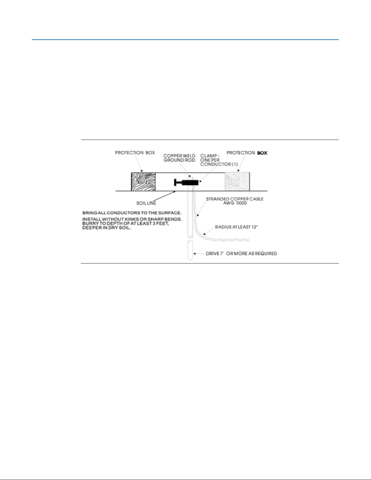
A basic ground consists of a 3/4-inch diameter rod with a minimum length of 8 feet driven into
conductive earth to a depth of about 7-feet as shown in Figure 3-1. Use braided copper wire for the
ground wire. The end of the wire should be clean, free of any coating, and fastened to the rod with
a clamp. Cover or coat this ground connection to protect it from the weather and the environment.
Figure 3-1: Basic Ground Rod Installation
3.3.1.1 Soil Conditions
Before installing a ground rod, analyze the soil type and moisture content. Ideally, the soil should
be moist and moderately packed throughout to the depth of the ground rod. However, some soils
may exhibit less-than-ideal conditions and may require extra attention.
With respect to establishing and maintaining a good earth ground, soil types fall into either of two
general categories: “good” soil and “poor” soil.
To be a good conductor, soil must contain some moisture and free ions (from salts in the soil). In
rainy areas, the salts may be washed out of the soil. In sandy or arid areas the soil may be too dry
and/or salt-free to a good conductor. If salt is lacking, add rock salt (NaCl); if the soil is dry, add
calcium chloride (CaCl2).
Site Considerations for Equipment Installation, Grounding, and Wiring Manual
D301452X012
September 2019
Grounding and Isolation 9
3.3.1.2 Soil Types
Table 3-1 details good and poor soil types.
Table 3-1: Soil Types
Good
Poor
Damp Loam
Back Fill
Salty Soil or Sand
Dry Soil
Farm Land
Sand Washed by a Lot of Rain
Dry Sand (Desert)
Rocky Soil
Always test ground beds for conductivity prior to placing any equipment in service. This section
provides a brief description of ground bed testing in both “good soil” and “poor soil.” Details on
this test are described in the National Electrical Code Handbook. Once you establish a reliable
ground, test it routinely to preserve system integrity.
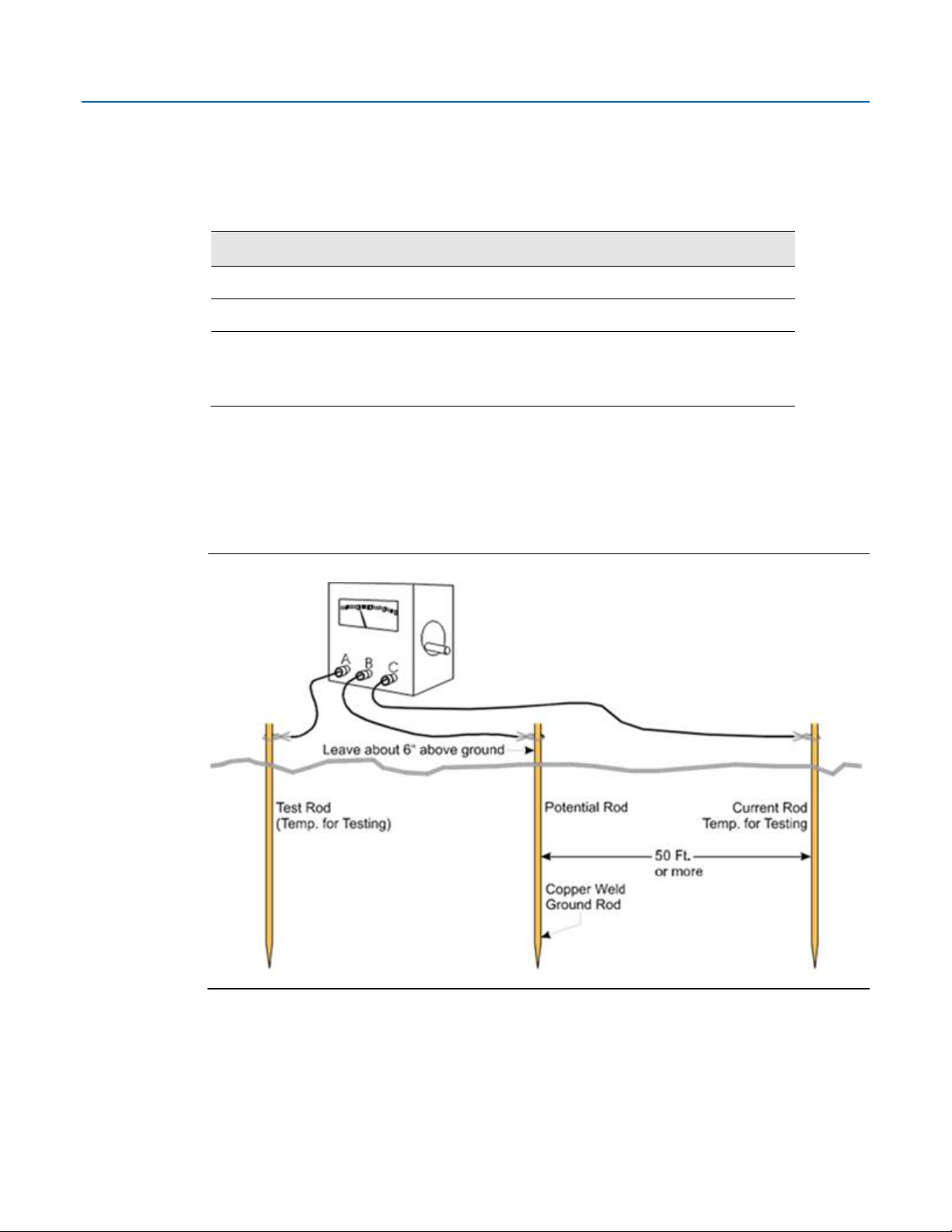
Figure 3-2 shows the test setup for “good soil” conditions.
Figure 3-2: Basic Ground Bed Soil Test Setup
If the ground resistance testing unit (GRTU, such as a Meggar® High-Performance Ground
Resistance Tester or an Associated Research Vibroground) reads less than 5 ohms, consider the
ground “good”: the lower the resistance, the better the earth ground. If the GRTU reads more than
10 ohms, the ground is “poor.” If a poor ground is indicated, drive one or more additional ground
rods connected 10 feet from the main ground rod into the soil and interconnect them via bare
AWG 0000 copper wire and 1” x ¼-20 cable clamps (as shown in Figure 3-3).
 Loading...