

Page 1

Instruction Manual
D104239X012
Service Manual for Multiport Flow
™
Selector
Valve
Multiport Flow Selector
April 2022
Contents
Introduction 1.................................
Specifications 3................................
Installation 4..................................
Field Technician Commissioning Activities 5.......
Reinstallation of the Actuator Assembly 5.....
Home Port Calibration 6....................
Electric Actuator Setup 6....................
Maintenance 7.................................
Disassembly 7.................................
Assembly 8....................................
Body 8......................................
Plug 8.......................................
Bonnet 9.....................................
Plug Seal Adjustment 10........................
Troubleshooting 11.............................
Drawing Assembly 12...........................
Parts List 15...................................
Maintenance Checklist Procedure 18..............
Multiport Electric Actuator 19....................
Figure 1. Fisher Multiport Flow Selector Valve
X1398
Introduction
Scope of Manual
This instruction manual includes installation, operation, and maintenance information for the Multiport Flow Selector.
Do not install, operate, or maintain a Multiport Flow Selector without being fully trained and qualified in
valve, actuator, and accessory installation, operation, and maintenance. To avoid personal injury or
property damage, it is important to carefully read, understand, and follow all the contents of this
manual, including all safety cautions and warnings. If you have any questions about these instructions,
contact your Emerson sales office
www.Fisher.com
before proceeding.
Page 2

Multiport Flow Selector
April 2022
Instruction Manual
D104239X012
Description
The Multiport Flow Selector offers an efficient solution for oil well testing. This valve has eight inlets, one test outlet,
and one group outlet. Eight pipe lines can be connected to this valve and allows continuous flow while
sampling/testing individual oil wells.
Educational Services
For information on available courses for the Multiport Flow Selector valve, as well as a variety of other products,
contact:
Emerson Automation Solutions
Educational Services - Registration
Phone: 1-641-754-3771 or 1-800-338-8158
E-mail: education@emerson.com
emerson.com/fishervalvetraining
2
Page 3

Instruction Manual
D104239X012
Multiport Flow Selector
April 2022
Specifications
The Multiport Flow Selector specifications are given in tables 1 through 5.
Table 1. Valve Specifications NPS 2x4 and 3x6
SPECIFICATIONS
ASME Class Rating
Weight, kg (lb) 91 (200) 91 (200) 363 (800) 553 (1220) 630 (1390) 658 (1450) 680 (1500) 968 (2135)
Inlet Ports NPS 2 NPS 3
Test Outlet Port NPS 2 NPS 3
Group Outlet Port NPS 4 NPS 6
End Connections Raised-face flanges (ASME B16.5) or threaded connections for NPS 2x4 constructions only
Temperature Range
Shutoff Class IV per ANSI/FCI70-2 and IEC 60534-4
1. The pressure/temperature limits in this instruction manual and any applicable standard or code limitation should not be exceeded.
2. Standard O-ring material established upper and lower temperature limits.
(1)
(2)
CL300 CL600 CL900 CL150 CL300 CL600 CL900 CL1500
2 x 4 3 x 6
Table 2. Valve Specifications NPS 4x8, 4x10, and 6x16
SPECIFICATIONS
ASME Class Rating CL300 CL600 CL900 CL1500 CL300 CL600 CL900 CL1500
Weight, kg (lb)
Inlet Ports NPS 4 NPS 4 NPS 6
Test Outlet Port NPS 4 NPS 4 NPS 6
Group Outlet Port NPS 8 NPS 10 NPS 16
End Connections Mates with raised-face flanges per ASME B16.5
Temperature Range
Shutoff Class IV per ANSI/FCI70-2 and IEC 60534-4
1. The pressure/temperature limits in this instruction manual and any applicable standard or code limitation should not be exceeded.
2. Standard O-ring material established upper and lower temperature limits.
(1)
959
(2115)
4 x 8 4x10 6 x 16
975
(2150)
1134
(2500)
VALVE SIZE
-1 to 204°C (30 to 400°F)
VALVE SIZE
1742
(3840)
-1 to 204°C (30 to 400°F)
1810
(3990)
2018
(4450)
3590
(7915)
5343
(11780)
Table 3. Actuator Specifications
VALVE SIZE AND ASME CLASS RATING
SPECIFICATIONS
Max Torque Output,
Nm (ftlbf)
Actuator Speed, RPM 1.0 0.5-1.0 0.5-1.0 0.5-1.0 0.3-0.5
Actuator Weight, kg (lb) 82 (180)
Plug Position Accuracy ± 1°
NPS 2 x 4
CL300/600/900
203 (150) 881 (650) 1085 (800) 1085 (800) 2034 (1500)
NPS 3 x 6
CL150/300/
600/900/1500
NPS 4 x 8
CL300/600/900
NPS 4 x 10
CL1500
NPS 6 x 16
CL300/600/
900/1500
3
Page 4

Multiport Flow Selector
April 2022
Instruction Manual
D104239X012
Installation
Minimum Tools Required
A torque wrench, socket wrench, and Allen head wrenches are required to install the Multiport Flow Selector Valve and
actuator assembly.
Table 4. Socket Size for Multiport Bonnet Studs and Nuts
VALVE SIZE, NPS ASME CLASS RATING SOCKET SIZE (in)
CL300
2 x 4
3 x 6
4 x 8
4 x 10 CL1500 2-3/4
6 x 16
CL600
CL900
CL150
CL300
CL600
CL900
CL1500 2-3/8
CL300
CL600
CL900
CL300
CL600
CL900 3-1/8
CL1500 3-7/8
1-5/8
2
2-3/16
2-9/16
Other socket sizes (inch) required: 7/16, 1/2, 9/16, 3/4, 7/8, and 1-1/8.
Allen key sizes (inch) required: 5/32, and 1/4
Table 5. Wrench Sizes (Inch) for Multiport Inlet and Outlet Flanges
FLANGE SIZE, NPS
2 - - - 1-1/16 1-1/16 1-7/16 - - -
3 1-1/16 1-1/4 1-1/4 1-7/16 1-13/16
4 - - - 1-1/4 1-7/16 1-13/16 2
6 1-1/4 1-1/4 1-5/8 1-13/16 2-3/16
8 - - - 1-7/16 1-13/16 2-3/16 - - -
10 - - - - - - - - - - - - 2-15/16
16 - - - 2 2-3/8 2-9/16 3-7/8
CL150 CL300 CL600 CL900 CL1500
ASME CLASS RATING
WARNING
Always wear protective gloves, clothing, and eyewear when performing any installation operations to avoid personal
injury. Check with your process or safety engineer for any additional measures that must be taken to protect against
process media.
Avoid personal injury and property damage by keeping hands, tools, and other objects away from the plug while operating
the valve.
Observe all WARNING decals and tags.
4
Page 5

Instruction Manual
D104239X012
Multiport Flow Selector
April 2022
Key numbers in this procedure are shown in figure 2 and 3 unless otherwise indicated.
Before installing the unit, observe all warning tags and:
1. Check for external physical damage.
2. Check for any visible leakage of gear oil from the Multiport Electric Actuator (MPA).
3. Visually inspect the inside of the Multiport through the group outlet port checking for damage, rust, and/or debris.
4. Verify the voltage requirement of the MPA (AC/DC) and connect power supply and signal circuits to test the
operation of the electric actuator and plug. Check for proper plug alignment at each port.
5. Inspect connecting piplines to be certain they are free of foreign material such as pipe scale or weld slag that could
damage the sealing surfaces fo the Multiport Flow Selector valve.
6. Provide appropriate flange gaskets and install them between the pipe flanges and valve body flanges. Tighten
flange bolting in a star pattern to ensure uniform compression of the gaskets.
Note
To prevent seal damage when hydrotesting external piping, position the plug midway between two inlet ports in order to equalize
pressure between the plug and valve body.
The Multiport Flow Selector plug/port alignment is factory adjusted when supplied with an actuator and should not require further
adjustment.
Field Technician Commissioning Activities
Refer to the Multiport Actuator (MPA) O&M Manual — Supplied by Bettis (MPA-400-0711). See page 19 for detailed
commissioning activities.
CAUTION
Replace pipe plug with breather before operating unit. The valve body may be pressurized from hydrostatic testing. Do not
remove any bolts or flanges for inspection until after the unit has been depressurized.
Circuit boards are susceptible to damage from static discharge when touched. Ensure that you ground yourself before
touching the knobs on the electric actuator.
Reinstallation of the Actuator Assembly
1. Using a manual wrench, rotate the plug (key 2) a few revolutions to verify it turns freely. Initial effort required to
rotate the plug could be high if the plug has not been rotated for an extended period of time.
2. Secure the actuator mounting bracket (key 43) to the bonnet using two cap screws (key 44), two travel indicator
studs (key 54), and four lock washers (key 56). For the NPS 2x4 construction, secure the lower plate to the bonnet
using two cap screws, two travel indicator studs and nuts, and four lock washers.
Regardless of size, apply an anti-seize lubricant (key 40) to the threaded portion of the fasteners. The cap screws
should be spaced 180 degrees apart from one another and 90 degrees apart from the travel indicator studs.
3. Secure the travel indicator plate to the travel indicator studs by tightening two cap screws (key 55). Proper
assembly has occurred if the lock washers have been placed between the travel indicator studs and travel indicator
plate and if flat washers (key 57) have been placed between the cap screws and travel indicator plate. For the 2x4
construction, place travel indicator spacers over the travel indicator studs and secure the travel indicator plate
5
Page 6

Multiport Flow Selector
April 2022
down by tightening the nuts. Proper assembly has occurred if there are flat washers between the travel indicator
spacers and travel indicator plate and travel indicator plate and nuts.
Instruction Manual
D104239X012
Regardless of size, an anti-seize lubricant (key 40) shall be applied to the threaded portion of the fasteners and nuts
4. To complete the assembly of the mounting kit for the NPS 2x4 construction, thread four spacer studs into the lower
plate and secure the upper plate to the spacer studs using four cap screws. Proper assembly has occurred if there
are lock washers between the lower plate and spacer studs and spacer studs and upper plate. An anti-seize lubricant
(key 40) shall be applied to the threaded portion of the studs and fasteners.
5. Apply grease (key 41) to the surfaces on the key slot(s) found on the shaft coupler (key 47). Insert key(s) (key 48)
into the shaft coupler key slot(s). Insert the shaft coupler with key(s) into the bottom of the Multiport Electric
Actuator and hold in place by hand.
6. Slowly lower the actuator with shaft coupler (key 47) onto the mounting bracket (key 43). Align the shaft coupler
with the square end of the plug (key 2). Position the shaft coupler such that the reference mark on the square end of
the plug remains visible between the flats of the shaft coupler. This reference mark indicates the location of the seal
assembly relative to the inlet ports of the body.
7. Attach the actuator to the mounting bracket (key 43) using four cap screws (key 45) and four lock washers (key 46).
Tighten these fasteners finger tight only.
8.
Apply an anti-seize lubricant (key 40) to the travel indicator holder (key 49) and thread on the jam nut (key 51), as
well as the travel indicator pointer (key 50) and nut (key 52). Thread this assembly into the shaft coupler (key 47).
The travel indicator pointer shall be on the same side as the reference mark found on the square end of the plug and
shall be positioned such that it will not contact any parts of the travel indicator assembly while rotating.
9. Using the electric actuator, rotate the plug (key 2) a few revolutions to establish proper alignment between the
shaft coupler (key 47) and plug. Visually check for any binding and adjust the position of the actuator as necessary.
Once the proper alignment has been established, secure the actuator to the mounting bracket (key 43) by
tightening the cap screws (key 46).
Home Port Calibration
.
Refer to the Multiport Electric Actuator (MPA) O&M Manual — Supplied by Bettis (MPA-400-0711) for detailed
instructions on how to calibrate the home port position.
Multiport Electric Actuator Set Up
Refer to the Multiport Electric Actuator (MPA) O&M Manual — Supplied by Bettis (MPA-400-0711) for detailed
instruction on:
1. Disabling port positions
2. Controller address
3. Control room MODBUS RTU operation
4. Installation and use of MPA software on laptop/PC
6
Page 7

Instruction Manual
D104239X012
Multiport Flow Selector
April 2022
Maintenance
Refer to figure 2 and 3, typical Multiport assembly and mounting drawings.
WARNING
Avoid personal injury from sudden release of process pressure. Before performing any maintenance operations:
D Do not remove the actuator from the valve while the valve is still pressurized.
D Disconnect any operating lines providing air pressure, electric power, or a control signal to the actuator. Be sure the
actuator cannot suddenly rotate the plug.
D Use bypass valves or completely shut off the process to isolate the Multiport from process pressure. Relieve process
pressure from all parts of the valve. Drain the process media from all sides of the Multiport.
D Use lockout procedures to be sure the above measures stay in effect while you work on the equipment.
D Always wear protective gloves, clothing and eyewear when performing any maintenance operations to avoid personal
injury.
D The tapered roller bearing area may contain process fluids that are pressurized, even when the valve has been removed
from the pipeline. Process fluids may spray out under pressure when separating the bonnet from the plug.
D Check with your process or safety engineer for any additional measures that must be taken to protect against process
media.
The Multiport Flow Selector valve is shipped completely greased and lubricated. Routine maintenance of this valve is
recommended, especially if it has been stored for an extended amount of time. Maintenance steps include:
1. Keeping the tapered roller bearing (key 3) greased. A high temperature silicone grease (key 39) can be injected into
the bearing housing through the lube fitting (key 28).
2. Confirming proper alignment between the plug and inlet ports.
D Verify the correct placement of the travel indicator pointer (key 50) onto the coupler (key 47).
D Align the plug (key 2) with one of the inlet ports. Confirm the travel indicator pointer is in alignment with the
selected inlet port.
3. Visual inspection of the seal insert (key 12). The sealing surface of this insert should be smooth and completely
intact.
D If the seal insert needs to be replaced, replace all o-rings (key 5, 7, 14, 20, 25, and 26), backup rings (key 6, 8, 15,
and 21), rod seal (key 4), plug bushing (key 9), and wiper seals (key 24).
4. Rotate the plug (key 2) one complete revolution using the electric actuator to confirm the assembly is functioning
properly. Check the local display unit on the electric actuator for any alarm codes.
Disassembly
Review warnings found in the Maintenance section of this manual.
Refer to figures 2 and 3 when disassembling the Multiport Flow Selector.
7
Page 8

Multiport Flow Selector
April 2022
Note
The bonnet can be removed with the Multiport Electric Actuator still attached. If this is done, ensure proper orientation has been
maintained between the actuator and valve body once the bonnet has been re-installed onto the valve body. If this orientation has
not been maintained, recalibration of the actuator is required. One way to ensure proper orientation has been maintained is to
place alignment marks between the plug (key 2) and coupler (key 47) prior to removal of the bonnet (key 19).
1. Rotate the plug (key 2) to any unused inlet port. Remove the blind flange from this inlet port to gain access to the
seal assembly. Once the adjustment tool has been secured to the seal adjuster (key 18), rotate this tool clockwise
until it stops. This action unloads the wave springs (key 11, 17) and removes the forces generated between the seal
insert (key 12), valve body (key 1) and scraper (key 12)/valve body (key 1).
2. Remove the nuts (key 32) from the bonnet (key 19), lifting lugs (key 33), and the studs (key 31) from the body (key
31). Thread eye bolts into the jack screws holes provided in the bonnet. Raise the bonnet vertically until it clears the
plug (key 2) and move it to the side.
3. Remove the plug (key 2) from the valve body (key 1). The seal components should still be installed inside of the
plug.
4. Remove the seal assembly from the plug (key 2) using the adjustment tool as follows:
D Once the adjustment tool has been inserted into the seal adjuster (key 18) and secured, rotate the tool
counterclockwise until the seal adjuster disengages from the final thread on the plug.
Instruction Manual
D104239X012
D With the adjustment tool still secured to the seal adjuster (key 18), pull it out of the plug. All components that
make up the seal assembly are now outside of the plug.
5. Carefully remove the bearing cup (key 3) from the bonnet (key 19).
6. Inspect all components for damage. Replace any damaged parts and reassemble by following the Assembly
procedure in this manual.
Assembly
Refer to figures 2 and 3 when assembling the Multiport Flow Selector.
Ensure all parts are clean and in good condition before assembling the Multiport Flow Selector. Refer to figure 2 to
determine which components require lubrication.
Body (Key 1)
1. Visually inspect all internal and external surfaces and threads.
2. Install the plug bushing (key 9) into the lower section of the body.
Plug (Key 2)
1. Install the lower plug O-ring (key 8), with the correct number of backup rings (key 7). For ASME rated CL150, 300,
600, and 900 valves, install one backup ring above (on the side nearest to the bonnet) the O-ring. For CL1500 rated
Multiports, install two backup rings one on either side of the lower plug O-ring.
2. Lubricate and install the seal adjuster (key 18) by turning it clockwise (i.e. viewing toward the plug centerline) until
solid. Follow with the correct number of wave springs (key 17). For NPS 2x4, 3x6, and 6x16 constructions, install
three wave springs. For NPS 4x8 and 4x10 constructions, install four wave springs. Ensure the wave springs are
properly aligned and seated on the seal adjuster.
Note
If the wave springs are not properly aligned and seated then the seal assembly may not function properly.
8
Page 9

Instruction Manual
D104239X012
3. Install the back up plate (key 16) against the shoulder in the plug (key 2).
4. Install the O-ring (key 14) onto the seal carrier (key 13). Install the seal assembly into the plug. Hand force should
only be required for proper installation.
5. Install the correct number of wave springs (key 11) followed by the scraper (key 10) into the plug over the seal
assembly. For NPS 2x4 constructions, install two wave springs and for NPS 3x6, 4x8, 4x10, and 6x16 constructions,
install one wave spring.
both hands then letting go to see if it returns to its original position.
6. Lower the plug (key 2) into the body ensuring that the seal insert (key 12) and scraper (key 10) clear the bore of the
body (key 1). When installed, the plug rests on top of the plug bushing (key 9).
7. Lubricate the tapered bearing cone and rollers (key 3) using a high temperature silicone grease (key 39) and install
onto the plug.
Ensure the scraper fits freely into the plug. Check by pushing the scraper into the plug using
Multiport Flow Selector
April 2022
Bonnet (Key 19)
1. Lubricate and press fit the bearing cup (key 3) into the bonnet using a high temperature silicone grease (key 39).
Lubricate the bearing cup and press fit it into the bonnet.
2. Install the backup ring (key 6), O-ring (key 5), and rod seal (key 4) into the bonnet bore. Rod seal is not required for
NPS 2x4 or 3x6 CL300, 600, and 900 rated valves.
3. Install the bonnet O-ring (key 20) into the groove of the bonnet. For NPS 4x8, 4x10, and 6x16 constructions, install
the backup ring above this O-ring.
4. Install the wiper seal (key 24), lube fitting (key 28), and vent plug (key 27). For NPS 4x10 and 6x16 constructions,
install the wiper seal on an external wiper retainer (key 24) with two extra O-rings (key 25 and 26).
5. Using two eye bolts threaded into the jack screw holes found on the bonnet, slowly lower the bonnet onto the
body. Be careful not to damage any soft parts when feeding the plug through the bonnet. The bonnet has been
properly positioned onto the body when the following has been achieved:
D The bolt holes in the bonnet have been aligned with the stud holes in the body.
D The centerline of the bonnet vent port has been aligned with the centerline of the group outlet of the body.
Excessive force should not be required to properly seat the bonnet onto the body. For NPS 2x4, 3x6, and 4x8
constructions, use hoist rings or eye bolts with 1/2 UNC threads. For NPS 3x6 CL1500, 4x10, and 6x16
constructions, use hoist rings or eye bolts with 3/4 UNC threads.
6. Lubricate studs (key 31) with an anti-seize lubricant (key 40) and thread into valve body (key 1). Place the
appropriate number of lifting lugs (key 33) over these studs. The placement of these lifting lugs should be equally
spaced with one being located directly above the group outlet. The placement of these lifting lugs is as follows:
D For NPS 2x4, 3x6, 4x8, and 4x10 constructions, place two lifting lugs equally spaced with one being located
directly above the group outlet port.
D For NPS 6x16 CL300, 600, and 900 constructions, place three lifting lugs equally spaced with two of them
straddling the group outlet port.
D For NPS 6x16 CL1500 constructions, place four lifting lugs equally spaced with two of them straddling the group
outlet port.
7. Lubricate the threads and the bottom surface of the nuts (key 32) with an anti-seize lubricant (key 40) paste prior to
threading them on to the studs (key 31). Once all nuts have been threaded hand tight, tighten two nuts spaced
180-degrees apart to the recommended torque values per table 6. Rotate the plug (key 2) one complete revolution
to ensure that it rotates with minimal resistance. If the plug rotates smoothly, then proceed to tighten the
remaining nuts using an appropriate tightening pattern.
8. Using the lube fitting (key 28), fill the bearing bore with grease.
9
Page 10

Multiport Flow Selector
April 2022
Instruction Manual
D104239X012
Table 6. Bonnet Bolting Torque
VALVE SIZE,
NPS
2 x 4
3 x 6
4 x 8
4 x 10 1500 44.5 1-3/4 1356 1000
6 x 16
ASME
CLASS RATING
300
600
900
150
300
600
900
1500 38.1 1-1/2 814 600
300
600
900
300
600
900 50.8 2 2034 1500
1500 63.5 2-1/2 4203 3100
STUD SIZE TORQUE
mm Inch Nm ftlbf
25.4 1 217 160
31.8 1-1/4 441 325
34.9 1-3/8 651 480
41.3 1-5/8 1085 800
Plug Seal Adjustment
1. Prior to adjusting the seal assembly (key 12 and 13), align the plug (key 2) with an open inlet port and insert the
supplied adjustment tool. Once this tool has been secured to the seal adjuster (key 18), rotate this tool counter
clockwise until the scraper (key 10) touches the inside surface of the body (key 1). The resistance to rotate the
adjustment tool will increase once the scraper contacts the body. Remove the adjustment tool.
2. Rotate the plug (key 2) a few revolutions to check for binding or excessive turning torque. If the plug rotates
smoothly, then insert, secure, and rotate the adjustment tool counter clockwise to tighten the seal adjuster (key
18) to the appropriate torque value listed in table 7.
Note
Do not exceed the torque values listed in table 7. Exceeding these values may cause the valve to not function as intended.
Table 7. Plug Seal Torque
VALVE SIZE, NPS ASME CLASS RATING
2 x 4
3 x 6
4 x 8
4 x 10 1500 54 40
6 x 16
300
600
900
150
300
600
900
1500
300
600
900
300
600
900
1500
Nm ftlbs
TORQUE
41 30
48 35
41 30
54 40
95 70
10
Page 11

Instruction Manual
D104239X012
3. Rotate the plug (key 2) a few revolutions while checking for smooth movement. If the seal assembly is binding
during rotation, then the seal assembly or the wave springs (key 17) are not in their proper position(s). See
disassembly procedure, if required.
4. Install the appropriate amount of pipe plugs (key 27).
5. Perform any required functionality test(s).
Multiport Flow Selector
April 2022
Troubleshooting
Actuator Does Not Align Plug to Inlet Port
1. Check the shaft coupler for looseness.
2. Check the motor for stalling or overload.
3. Check the visual leakage or noisy gear.
4. Refer to the Multiport Electric Actuator (MPA) O&M Manual — Supplied by Bettis (MPA-400-0711
calibration procedures and troubleshooting.
Seal Leakage
1. Check the travel indicator plate (key 53) and travel indicator pin (key 50) to ensure the plug (key 2) is properly
aligned with the inlet ports.
2. Check the seal insert (key 12) for damage. To visually inspect the seal insert, the blind flange from an unused inlet
port needs to be removed. Prior to removing this flange, verify the Multiport Flow Selector valve has been
depressurized to a value of zero. With the blind flange removed, rotate the plug until visual inspection of the seal
insert can occur. The sealing surface of the seal insert should be smooth, completely intact, and free of deep groove
marks.
) for port
WARNING
Ensure that all pressures in the Multiport body, group outlet, and test port are ZERO before visually checking the seal.
3. If more information is required, please contact your Emerson sales office.
11
Page 12

Multiport Flow Selector
April 2022
Figure 2. Multiport Drawing Assembly
Instruction Manual
D104239X012
VIEW C
VIEW D
VIEW B
VIEW E
VIEW B
SCALE 2:1
VIEW A
VIEW D
SCALE 2:1
VIEW E
SCALE 3:1
VIEW A
SCALE 2:1
GE99805
APPLY LUB/SEALANT
PARTS NOT SHOWN: 30, 34, 35, 36, AND 37.
12
VIEW C
SCALE 2:1
Page 13

Instruction Manual
D104239X012
Figure 3. Multiport Mounting Assembly for NPS 2x4 Constructions
Multiport Flow Selector
April 2022
GE99891
Figure 4. Multiport Mounting Assembly for NPS 3x6, 4x8, and 6x16 Constructions
GE99891
13
Page 14

Multiport Flow Selector
April 2022
Parts Kits
Seal Kits
DESCRIPTION PART NUMBER
MINOR REPAIR KIT, 316 FOR 2X4 MPFS RMPFS20409X072
MINOR REPAIR KIT, AFLAS FOR 2X4 MPFS RMPFS20409X052
MINOR REPAIR KIT, AFLAS/FLEXISEAL FOR 2X4 MPFS RMPFS20409X062
MAJOR REPAIR KIT, 316 FOR 2X4 MPFS RMPFS20409X082
MAJOR REPAIR KIT, AFLAS FOR 2X4 MPFS RMPFS20409X012
HIGH DIFFERENTIAL PLUG UPGRADE, AFLAS/FLEXISEAL FOR 2X4 MPFS RMPFS20409X042
MINOR REPAIR KIT, 316 FOR 3X6 MPFS RMPFS30609X102
MINOR REPAIR KIT, AFLAS FOR 3X6 MPFS RMPFS30609X082
MINOR REPAIR KIT, AFLAS/KALREZ FOR 3X6 MPFS RMPFS30609X092
MINOR REPAIR KIT, AFLAS/25CFT/DSS FOR 3X6 MPFS RMPFS30609X022
MINOR REPAIR KIT, AFLAS/25CFT/825 FOR 3X6 MPFS RMPFS30609X112
MAJOR REPAIR KIT, 316 FOR 3X6 MPFS RMPFS30609X132
MAJOR REPAIR KIT, AFLAS FOR 3X6 MPFS RMPFS30609X042
MAJOR REPAIR KIT, AFLAS/25CFT/DSS FOR 3X6 MPFS RMPFS30609X032
MAJOR REPAIR KIT, AFLAS/25CFT/825 FOR 3X6 MPFS RMPFS30609X122
HIGH DIFFERENTIAL PLUG UPGRADE, AFLAS FOR 3X6 MPFS RMPFS30609X062
Instruction Manual
D104239X012
MINOR REPAIR KIT, 316 FOR 4X8 MPFS RMPFS40809X112
MINOR REPAIR KIT, AFLAS/VITON FOR 4X8 MPFS RMPFS40809X102
MINOR REPAIR KIT, 718 FOR 4X8 MPFS RMPFS40809X022
MINOR REPAIR KIT, AFLAS/25CFT/825 FOR 4X8 MPFS RMPFS40809X032
MINOR REPAIR KIT, AFLAS/25CFT/SDS FOR 4X8 MPFS RMPFS40809X132
MAJOR REPAIR KIT, 316 FOR 4X8 MPFS RMPFS40809X122
MAJOR REPAIR KIT, AFLAS FOR 4X8 MPFS RMPFS40809X072
MAJOR REPAIR KIT, 4X8 MPFS RMPFS40809X082
MAJOR REPAIR KIT, AFLAS/25CFT/DSS FOR 4X8 MPFS RMPFS40809X042
MAJOR REPAIR KIT, AFLAS/25CFT/718 FOR 4X8 MPFS RMPFS40809X052
MAJOR REPAIR KIT, AFLAS/25CFT/825 FOR 4X8 MPFS RMPFS40809X062
MAJOR REPAIR KIT, AFLAS/25CFT/SDS FOR 4X8 MPFS RMPFS40809X142
HIGH DIFFERENTIAL PLUG UPGRADE, AFLAS FOR 4X8 MPFS RMPFS40809X092
Adjustment Tool Kits
DESCRIPTION PART NUMBER
ADJUSTMENT TOOL 2x4 CL 300, 600, and 900 RMP20409X012
ADJUSTMENT TOOL 3x6 CL 150, 300, 600, and 900 RMP30609X012
ADJUSTMENT TOOL 3x6 CL 1500 RMP30615X012
ADJUSTMENT TOOL 4x8 CL 300, 600, and 900 RMP41015X012
ADJUSTMENT TOOL 4x10 CL 1500 RMP41015X012
ADJUSTMENT TOOL 6x16 CL 300, 600, and 900 RMP61609X012
ADJUSTMENT TOOL 6x16 CL 1500 RMP61625X012
14
Page 15

Instruction Manual
D104239X012
Multiport Flow Selector
April 2022
Parts List
WARNING
Use only genuine Fisher replacement parts. Components that are not supplied by Emerson should not, under any
circumstances, be used in any Fisher valve, because they may void your warranty, might adversely affect the performance
of the valve, and could cause personal injury and property damage.
Key Description
Note
Contact your Emerson sales office
Multiport Assembly
(see figure 2 and 3)
Key Description
1 Valve Body
2 Plug
3 Bearing
4 Rod Seal
5 O-Ring, upper plug
6 Back up Ring, upper plug
7 O-Ring, lower plug
8 Back up Ring, lower plug
9 Plug Bushing
10 Scraper
11 Wave Spring Scraper
12 Seal Insert
13 Seal Carrier
14 O-Ring
15 Back up Ring
16 Back up Plate
17 Wave Spring
18 Seal Adjuster
19 Bonnet
20 O-Ring
21 Back up Ring
22 Wiper Retainer
23 Cap Screw, Wiper Retainer
24 Wiper Seal
for part ordering information.
25 O-Ring, Wiper Retainer
26 O-Ring, Shaft
27 Pipe Plug
28 Lube Fitting
29 Pipe Bushing
30 Set Screw
31 Stud
32 Nut
33 Lifting Lug
38 White Petrolatum
39 High temperature silicone grease
40 Anti-seize lubricant
41 Grease
42 Thread sealant paste
43 Mounting Bracket
44 Cap Screw
45 Cap Screw
46 Lock Washer
47 Coupler
48 Key
49 Travel Indicator Holder
50 Travel Indicator Pointer
51 Jam Nut
52 Nut
53 Travel Indicator Plate
54 Travel Indicator Stud
55 Cap Screw
56 Lock Washer
57 Washer
58 Cap Screw
59 Bracket, Upper
60 Travel Indicator Spacer
61 Nut
62 Stud
63 Bracket, Lower
15
Page 16

Multiport Flow Selector
April 2022
Figure 5. Typical Multiport Seal Components
Instruction Manual
D104239X012
PLUG SEAL
WAVE SPRINGS
SCRAPER
X1581
SEAL
ADJUST
MENT
NUT
X1582
SEAL
ADJUSTMENT NUT
SCRAPER WAVE
SPRING
PLUG SEAL COMPONENTS
ASSEMBLY
SEAL WAVE
SPRINGS
SEAT RING/
PLATE/
O-RING/
SEAL INSERT
HIGH DIFFERENTIAL SEAL
BEARING
DIFFERENTIAL SEAL
SCRAPER
WAVE
SPRINGS
HIGH
SCRAPER
X1584
BACKUP
PLATE
X1583
O-RING
SEAT
RING
HIGH DIFFERENTIAL
SEAL ASSEMBLY
SEAL ADJUSTMENT TOOL
SEAL
INSERT
ASSEMBLY
NOTE:
1
PLUG SEAL ADJUSTMENT TOOL SHOWN WITH BASE PARALLEL TO SHANK FOR INSERTION, BASE PERPENDICULAR TO SHANK, AND ENGAGED IN SEAL ADUSTMENT NUT.
16
Page 17

Instruction Manual
D104239X012
Figure 6. Typical Multiport Seal Components
Multiport Flow Selector
April 2022
PLUG
E-60681009
NOTE:
1
PLUG (INDEX MARK CAN BE FOUND ON THE STEM FLAT THAT FACES THE SAME WAY AS THE PLUG SEAL OPENING.) PLUG SEAL ADJUSTMENT TOOL IN PLUG.
SEAL ADJUSTMENT TOOL
17
Page 18

Multiport Flow Selector
April 2022
Instruction Manual
D104239X012
Recommended Periodic Multiport Maintenance
Checklist Procedure
Half Yearly Check
1. Check the plug port position in the Local Display Module (LDM) and the mechanical indicator respectively and in
remote feedback.
2. Check the plug travel sequence for smooth operation with local/remote.
3. Lubricate the bearing through the grease nipple with high temperature silicone grease.
4. Visual Inspection of Multiport Flow Selector (MPFS) valve.
Annual Check
1. Visual Inspection of MSV.
2. Lubricate the bearing through the grease nipple with high temperature silicone grease.
3. Check the seal torque (refer chart) and seal visual condition.
4. Check the plug position in LDM and the mechanical indicator respectively and in remote feedback.
5. Check the plug travel sequence for smooth operation with local / remote.
6. Check mechanical operation (using manual override).
7. Check electrical connections of Multiport Actuator (MPA) (power and communication port).
8. Check the Torque Encoder and Position Encoder.
9. Visual check of shaft penetrations for lubrication leakage.
10. Inspect stem nut or bushing for wear / damage of Multiport Actuator.
11. Run online seal integrity test.
Visual Seal Inspection
1. Local Shutdown should be take by end user to isolate the Multiport valve.
2. Check the plug alignment visually at home port (blind flange open condition).
3. If the seal visual inspection and seal torque are deemed acceptable, then assemble the home flange and run on line
seal integrity test.
General
1. It is recommended to operate the Multiport, once in three weeks, at least one full rotation, if there is no well
testing. Not recommended to keep Multiport idle for more than 3 to 4 weeks.
2. Recommended to replace the seat ring (complete Seal Kit Assembly) and all the soft seals every 5 years.
18
Page 19

Instruction Manual
D104239X012
Multiport Flow Selector
April 2022
Multiport Actuator
O&M Manual — Supplied by Bettis
Document No. MPS-400-0711
WARNING
Use caution when working on, with, or around valves and actuators. High pressures, forces, voltages, and flammable
media can be present.
Read this manual in its entirety before installing, operating, or performing maintenance on the MPA valve actuator.
Failure to follow instructions for proper electrical wiring, storage, setup, and maintenance may cause serious injury,
damage equipment, or void the warranty. Refer to Manual E796 for instructions on storage, electrical hook-up, and
maintenance.
Ensure that the installation is carried out in accordance with EN 60079-14 and IEC 60079-14.
Regulatory information:
II 2 GD
EEx d IIB T4 or EEx d IIB 120° C (T4) Tamb -20° C to +60° C
Revision M
19
Page 20

Multiport Flow Selector
April 2022
Table of Contents
Introduction 21................................
Figure 1 – Typical Well Test Application 21........
Figure 2 - MPA mounted on 6x16 MPFS 22.........
Features 23....................................
Figure 3 – MPA Features 23.....................
Figure 4 – Local Display Module (LDM) 25.........
Figure 5 – MPA with Remote Display Module (RDM)26
Mechanical and Electrical Installation 26............
Wiring 27....................................
Power Wiring 27...........................
Network Wiring 27.........................
Monitor Relay Wiring 27....................
Local ESD Wiring (Emergency Shutdown) 27...
Optional Remote Display Module (RDM) Wiring27
Local Display Module 28........................
Figure 6 – LDM 28.........................
Operation 28.............................
Figure 7 – LDM 29.........................
Local Operation 29.........................
Operational Display 29.....................
Display Blanking 30.......................
Alarms Display 30.........................
Field Setup Using DCMLink
Figure 8 – DCMLink Setup 31....................
Figures 9 – 13 DCMLink Setup 32................
User Setups Menu 33..........................
Selecting New Home Port 34....................
Figure 14 – Change Home Port Setting 34.........
Home Port LED Function 34.....................
Home Port Calibration
Figures 15 and 16 35........................
Factory Setup 35..............................
Figures 17 – 20 – Factory Setup Port Calibration 36.
Motor Type 37............................
Figures 21 – 23 – Status Control 38...............
Field Controls 39..............................
Field Setup Using Local Controls 40................
Alarm History Display 41.......................
Setup Mode Display Sequence 41................
Field Diagnostics 44.............................
Fault Codes 44................................
Remote Control Network 45.....................
Modbus RTU 45...............................
Discrete Input Map (Valve Status and Alarms) … 45
Coil Map (Discrete Network Control) 45.......
Holding Register Map 46....................
Foundation Fieldbus (FF) 47.....................
Profibus DP Redundant Networks with Redcom 49..
DeviceNet 50.................................
EC Declaration of Conformity 51..................
Wiring Diagram – Three Phase Power 52...........
Wiring Diagram – Single Phase Power 53...........
Wiring Diagram – 24VDC Power 54................
™
Software 31...........
Instruction Manual
D104239X012
20
Page 21

Instruction Manual
D104239X012
Multiport Flow Selector
April 2022
Introduction
The Multiport Actuator (MPA) is a Bettis single turn actuator for control of Multiport Flow Selectors (MPFS) with 3 to 8
ports. A typical application is oil or gas well selection for well production testing as shown in figure 1. Typically the MPA
is the actuator of a Multiport Flow Selector as shown in figure 2. There are applications in other processes where
control of Multiport valves is required.
Figure 1. Typical Well Test Application
WELL 1
WELL 1
WELL 2
WELL 2
WELL 3
WELL 3
WELL 4
WELL 4
TO PRODUCTION
TO PRODUCTION
WELL 5
WELL 5
WELL 6
WELL 6
WELL 7
WELL 7
TO TEST SEPARATOR
TO TEST SEPARATOR
21
Page 22

Multiport Flow Selector
April 2022
Figure 2. MPA Mounted on 6”x16” MPFS
Instruction Manual
D104239X012
22
Page 23

Instruction Manual
D104239X012
Multiport Flow Selector
Features
The actuator features several assemblies as shown in figure 3. Unique features of the actuator are listed below.
April 2022
Figure 3. MPA Features
LOW VOLTAGE INTERFACES
BETWEEN CPU AND TBM
ELECTRICAL ENCLOSURE WITH MOTOR
STARTER, CONTROL TRANSFORMER,
DC POWER SUPPLIES, POWER ENTRY,
TERMINATION PANEL, USER WIRING,
I/O INTERFACES, TORQUE ENCODER
MOTOR
(NOT SHOWN)
LOCAL DISPLAY MODULE
(LDM) WITH DISPLAYS &
STATUS LEDS. SELECTOR
& CONTROL KNOBS, CPU
MODULE, NETWORK
COMMUNICATIONS,
POSITIONER ENCODER
POSITIONER
ENCODER
COUPLING TO
MPFS STEM
GEARBOX
INTEGRAL
DISCONNECT
1. MPA uses Bettis's heavy duty gearbox with capacity of 3000 ft•lbs
a. Wide range of motors available for any voltage and torque
2. Configurable for Multiport flow selectors from 3 to 8 ports
a. Any port may be selected as home port and any port(s) may be skipped
b. Actuator calibrated at factory for exact match to alignment of flow selector ports
c. Calibration parameters stored in nonvolatile memory and available to DCS
3. 12-bit magnetic encoder coupled directly to valve stem for precision position feedback
a. Provides position measurement resolution of 0.088 degrees
4. Bettis’s exclusive solid-state motor starter and control software provides precise positioning of flow selector within
+
0.26 degrees of selected port for the largest flow selector, and within +0.79 degrees for smallest flow selector,
where accuracy is less of a concern because of reduced radius
23
Page 24

Multiport Flow Selector
April 2022
Instruction Manual
5. High performance microcontroller updates motor control output every 4mS for precision motor control
6. 12-bit magnetic encoder coupled directly to torque pinion for torque feedback
a. Provides torque measurement resolution of 0.146% of full torque
7. MPA supports all network protocols available with all other Bettis actuators
D ModbusRS485 Bus or E>Net ring available
D Profibus Redundancy with Redcom
D Foundation Fieldbus
D DeviceNet
D Ethernet Modbus TCP/IP
8. I/O and alarm monitoring include:
D Integral circuit breaker/disconnect
D Motor overload and motor thermal
D104239X012
D Loss of control voltage
D Encoder failure
D Stall detection and alarming (detects mechanical faults)
D 3-Phase monitoring and phase correction to insure correct motor rotation
D ESD to send selector to home port (also goes to home port on fault)
D Monitor relay for hardwired relay contact status on fault
9. Four models support five 8-port MPFS (Also see motor type on page 33)
Table 1.
MODEL MPFS
MPA 150 2x4 150 203 1.0 1.0 1.0 0.79
MPA 650 3x6 650 881 0.7 1.0 0.5 0.49
MPA 800 4x8 and 4x10 800 1085 0.6 0.9 0.5 0.40
MPA 1500 6x16 1500 2034 0.3 0.4 0.3 0.26
Note: Accuracy based on worse case tests at 38% of maximum torque.
CAPACITY RPM ACCURACY
lb ft Nm 1Ph 3Ph DC Degrees
10. MPA includes local display module (LDM) standard
D Uses rugged, high visibility LED display for port number, torque, and alarms (also displays setup menus and setup
parameters)
D Multiple color LEDs display
a. Port position within 1° of port
24
Page 25

Instruction Manual
D104239X012
b. Port position within 2° of port
c. Motor running
d. Alarm
e. Over torque
f. Position within 0.25° of home port
g. Local mode 〉
h. Off mode 〉 Combined detection logic for two selector switches
i. Remote mode 〉
D Display blanking user setup option to conserve power in idle mode
D Includes Local Off Remote selector switch
D Local control knob for Port selection and Jog control when enabled by User
Multiport Flow Selector
April 2022
Figure 4. Local Display Module (LDM)
25
Page 26

Multiport Flow Selector
April 2022
11. Remote display module (RDM) option available
a. RDM displays identical information and performs identical control as LDM
b. Bettis's patented combined switch logic allows detection of selector switch position on LDM and RDM
c. Allows remote control up to 4,000 feet (1,220 meters) away
d. Alarming includes loss of communication with RDM
Figure 5. MPA with Remote Display Module (RDM)
Instruction Manual
D104239X012
Mechanical and Electrical Installation
Do not connect power until you have gone through the following checklist:
1. Does the information given on the nameplate correspond with the application?
2. Have all wire terminations and the equipotential bonding system been connected correctly?
3. EEx d applications: are the cable entries, plugs and adaptors EEx d approved?
4. Are all cable entries of the correct internal diameter providing a good seal around the cable?
5. Do the ambient and process temperatures correspond to the ratings on the nameplate as shown below?
26
Page 27

Instruction Manual
D104239X012
Multiport Flow Selector
April 2022
Wiring
All user wiring terminations are made inside the Electrical Enclosure shown in figure 3. Refer to wiring diagram located
at the back of this manual for wiring connections. High voltage power connections are made to the disconnect/circuit
breaker located inside the electrical enclosure. All low voltage connections, including network wiring, are made to the
Termination Board Module (TBM) located inside the electrical enclosure. Use conduit and seals in accordance with
National Electric Code (NEC) and local codes for all wiring entering the electrical enclosure.
Power Wiring
Connect power voltage leads to the circuit breaker located in the main electrical enclosure. Power wires must enter
the electrical enclosure at the conduit entry on the lower right side of the enclosure to prevent water from entering.
The controller provides automatic phase correction in case three-phase power is connected in the wrong phase
rotation.
Network Wiring
If a single bus network connection, such as Foundation Fieldbus, is being made, connect to Network Port A at TBM
terminals 24 (-) and 25 (+). If the cable is shielded, connect shield to TBM terminal 23. If redundant or repeater
network connections such as Bettis E>Net are being made, connect the second network to Network Port B at TBM
terminals 23 (+) and 24 (-). Connect cable shield of Port B to TBM terminal 25. Cable shields are isolated from earth in
the actuator. Connect shields to only one earth ground point in the network, normally the host location.
Monitor Relay Wiring
The Monitor Relay is used for hardwiring an indication of availability of the actuator for remote control. When the
selector switch is placed in the Remote mode and if there are no alarms present that prevent operation, the Monitor
Relay is energized. If an alarm occurs or the selector switch is moved from the Remote position, the relay is
deenergized. The Monitor Relay is a Form C relay with both normally open (N.O.) and normally closed (N.C.) contacts.
Wire to either TBM terminals 31 and 32 if N.O. contacts are desired. Wire to TBM terminals 32 and 33 if N.C. contacts
are desired. The relay is shown on the wiring diagram in the deenergized state, meaning that the actuator is not
available for remote control.
Local ESD Wiring (Emergency Shutdown)
Remove jumper between TBM terminals 27 and 28. Connect Normally Closed (N.C.) dry contacts to terminals 27 and
28. When the contacts open, ESD is activated, causing the actuator to go to Home Port. The actuator will remain at the
Home Port until the ESD contacts are closed and a new command is received from either Local or Remote control. The
ESD circuit is a closed loop failsafe circuit. It the circuit is opened for any reason, broken wire, bad contact, 24VDC
power supply failure, etc., the ESD function is activated. The closed loop circuit is powered by 24VDC from the
actuator.
Optional Remote Display Module (RDM) Wiring
Connect twisted pair RS485 cable from the RDM to TBM terminals 18 (-) and 19 (+). If the RDM is being powered from
the actuator 12VDC supply, wire the power wires from the RDM to TBM terminals 16 (-) and 17 (+). The RDM is polarity
protected, preventing damage, but will not operate if polarity is reversed.
27
Page 28

Multiport Flow Selector
April 2022
Instruction Manual
D104239X012
Local Display Module
Contains microprocessor controller, position encoder, and network interface. This is the main controller used to setup
and operate the actuator.
This module displays operating parameters, port position, torque, and alarms. It also provides a means to configure
the actuator by using the local controls.
To use the Local Control and Selector:
Note
Actuator moves in only the counterclockwise position.
Figure 6. Local Control and Selector
SELECTOR KNOB (right) ROTATE
OFF (Stop) [return position] Stop movement Prevents motor operation
REMOTE (Auto) Clockwise Remote control Allows control from remote location
LOCAL (Hand) Counter-clockwise Hand Operation
SELECTOR KNOB (left)
(while selector is in LOCAL
(hand)mode)
Spring return Neutral position No operation
PORT (up) Clockwise
Jog (dn) Counter-clockwise
ROTATE FUNCTION RESULTS
FUNCTION RESULTS
Allows Control from the local control knob or the
control knob of the RDM, if connected.
Releases a local command when Local control is
used
Local command
to go to next port
Local command
to micro-step
Commands actuator to move to the next port.
Momentary knob control
Commands actuator to move only
while knob is being held , i.e. maintained knob
control.
Operation
Place the “Selector Knob” in the desired operating position –
28
Page 29

Instruction Manual
D104239X012
Multiport Flow Selector
April 2022
LOCAL – hands on operation at the actuator by manipulation of Control Knob.
REMOTE – used within the context of plant operation, i.e. Remote Control Panel, PLC, DCS, etc. See wiring diagram for
typical user wiring for remote control.
OFF (Stop) – to prevent local or remote operation.
Figure 7.
Local Operation
Place the “Selector Knob” in the “Local” position. If a remote display is connected, the remote selector switch must not
be in the “Off” position. Verify that the selector “L” amber light is on. The actuator may now be operated using the
port and jog Control Knobs. Jog control is normally disabled and must be enabled in the setup menu.
To jog or micro-step the actuator toward the next port, rotate the control knob in the counterclockwise direction. Jog
to position and release when the desired position is reached. When using jog for calibrating the actuator, always stop
short of the desired port and use the hand wheel to complete accurate positioning to center of the port.
To move only to the next port, momentarily rotate the control knob in the clockwise direction to the Port position and
release.
To Stop or prevent actuator movement, move Selector knob to the OFF (Stop) position.
Operational Display
Operational indicators for RUN / ALARM / PORT position use long lasting LED’s. Run torque and port position are
shown on the digital readout during normal operation. Torque in percent of maximum is displayed as a 2-digit number
only while the motor is running. Port position is displayed as a single digit when the motor stops. If the actuator stops
between two ports, the two corresponding port numbers will alternate. Torque less than 10% is displayed as 0%.
RUN LED flashes Green while the actuator is moving to the next port and flashes Red while running within 2° of the
selected port position.
29
Page 30

Multiport Flow Selector
April 2022
Instruction Manual
D104239X012
PORT LED flashes Green when the actuator is within 2° and outside 1° prior to the setpoint of the selected port. The
port LED flashes Red when within 2° and outside 1° beyond the setpoint. The port LED illuminates steady Green while
within 1° of the selected port position.
ALARM (Yellow) LED flashes when any alarm is present. The LED is on solid when stopped between ports, otherwise it is
off.
OVER TORQUE alarm condition is indicated when a torque alarm occurs in mid-travel. The over torque LED will flash so
long as the over torque condition exists.
HOME PORT LED will light when the actuator is within 0.25° of the user selected Home Port position.
Selector switch LEDs are also made available for operational use in the bottom right corner. The selector LEDs are
important when using a Remote Display Module (RDM) because these LEDs indicate the combined logic of the two
selector switches, i.e. the selected mode of operation of the actuator. All three LOR LEDs flash while the actuator is in
setup mode.
Display Blanking
The user has the option to have the display blank out (turn off) when not in use. This is a very important feature for
solar power applications because power consumption is minimized. Option to enable or disable display blanking
timeout is available by setup using MPA Config or the control knobs. See the field setup section for selecting the
option. When control knobs are used for setup, the parameter is C9 as shown in the table on page 38. The default
setting is display blanking timeout enabled for 24VDC versions and disabled for AC versions. If display blanking is
enabled, the display will blank out after 60 seconds when left unattended while the selector switch is in Remote mode.
The display will blank out after 3 minutes when left unattended while the selector switch is in Local mode. The display
will not blank out while in setup mode. When selected, display blanking applies to both local (LDM) and remote (RDM)
displays.
Alarms Display
When an alarm occurs, it is automatically displayed by the two character LED display. The yellow ALARM LED will flash
while any alarm is present. The display will alternate between the current port position and the active alarm(s) except
when stopped between parts. If more than one alarm is active, the display will cycle through a sequence of Port
Position, newest alarm, Port Position, next oldest alarm and so on until all active alarms are displayed. The cycle is
continuously repeated until all alarms are cleared. Each alarm is recorded in an Alarm History. The alarm history may
be viewed by entering setup mode (see next section).
All possible alarms that may be displayed are listed on the name plate of the Local Display Module (LDM). Following are
definitions of the listed alarms.
CE Communication Error Lost communication with the Remote Display Module (RDM) when configured.
SA Stall Alarm Actuator failed to move within 8 seconds after commanded by either local or remote
LE Local ESD Hardwired Local Emergency Shut Down is active.
PH Phase Alarm Loss of one phase when configured for 3-Phase.
EF Encoder Failed Failure of either the position or torque encoders.
AF Actuator Failed A fault is detected by hardware electronics fault monitor. This is a non-recoverable
OL Motor Overload Motor thermals or motor overload relay has tripped.
LC Lost Control Voltage
Note
Over torque alarm is displayed by dedicated LED. See Operational Display section above.
controls.
condition that requires actuator service.
Loss of power to the motor control circuits. The control voltage supply has an
automatic resetting fuse.
30
Page 31

Instruction Manual
D104239X012
Multiport Flow Selector
April 2022
Field Setup Using DCMLink Software
DCMLink is an application for configuration, calibration, test, and operation of the MPA DCMLink is a licensed product.
It is a Windows-based program. Compatible Windows Operating Systems are listed in the DCMLink IOM,
DCM-402-0317.
Connection to the MPA to utilize DCMLink requires a RS485 link. The MPA supports several network protocols so it may
be necessary to use a USB to RS485 converter for connection of a PC to the RDM port of the actuator. RDM port is at
TBM terminals 18 (-) and 19 (+). DCMLink Software loaded to a laptop or other compatible PC device can connect the
RS485 link to the TBM in the electrical enclosure. If opening the enclosure is undesirable, configuration may be
performed using the local control knobs of the actuator as described in the next section of this manual. If the system is
configured for Modbus networking, the PC may be connected to the local area network at any location in the network
after disconnecting the Host system communication. The MPFS factory uses this software to configure and calibrate
the MPA and saves the configuration to a “.mpa” file by MPFS serial number. Should loss of factory configuration or
port calibration occur due to failure of a CPU module or user error, a copy of the file may be obtained from the MPFS
factory and loaded to the actuator using DCMLink program.
DCMLink SetUp
HELP: Clicking the Menu Bar Help Tab button at the
top of the screen will open linked documents or
information. Passing the cursor across the Icons or
Navigation Pane tabs will cause a description of that
item to be displayed.
To setup communication and DCMLink Display
Preferences, select the DCMLink Setup Tab in the
Menu Bar as shown in figures 8b and 8c. To configure
the network communication link select the
Communication Tab in Preferences per figure 9.
Figure 8a.
Figure 8b.
Figure 8c.
31
Page 32

Multiport Flow Selector
April 2022
Communications Setup
If connected to the RDM port, set the computer Baud
Rate to 9600, Parity None and Stop Bits to 1. Set the
Slave Address to 99. The RDM port configuration of the
MPA is fixed at 9600,N,8,1 and may not be changed by
the user.
If connected to a Modbus local area network, the baud
rate and slave address configured for the actuator
must be known in order to setup the computer
communication port. Default configuration for the
MPA network port is 19,200 baud and default address
is 99.
Select the configured Com Port in Navigation Pane and
Right Click to Scan for Devices. Set address and Start
Scan. When device is detected stop scan and close the
window .
Instruction Manual
D104239X012
Figure 9.
Figure 10.
32
Figure 11.
Page 33

Instruction Manual
D104239X012
User Setup Menus
To configure the actuator, select (highlight) the Device
Tag in the Navigation Pane per figure 12. Then Right
Click or use the Icon in the Menu Bar to select Detailed
Setup as shown in figure 13. The current Actuator
configuration and the default MPA settings or opened
Dataset settings are displayed. A Dataset is a file on
DCMLink based on the Device type and Displayed
Device Tag. A yellow Tab indicates there are
differences between the displayed Actuator
configuration and the displayed Dataset.
Configuration can be changed between the Actuator
and the Dataset and the actuator Configuration File
and Dataset can be saved to the PC. No passcode is
required to change User Configuration Settings
(Detailed Setup & Home Port Calibration) when using
DCMLink.
The Network Tab allows changes in configuration only
for the network ports. It does not affect the RDM port.
The Control Tab allows unused/unconnected Ports of
the MPFS to be bypassed. If a pipeline is not connected
to any one or more ports, or if it is desirable to skip any
one or more ports, click on the “Delete Port” number.
The deleted ports will be skipped when a next port
command is issued in either local or remote control
modes.
Multiport Flow Selector
April 2022
Figure 12.
Figure 13.
Notice: When configuration changes are made,
clicking the Blue arrows “Writes” the configuration to
the Actuator or Dataset. If there are no differnces
between the Actuator and Dataset, the arrows will be
grey. Using the dropdown box arrow of the Dataset
allows for parameter change selections to be made.
The “Read” button may be used to refresh the screen
to verify the parameters have been properly written for
storage in the actuator. You can read or write entire
configuration or just the opened page using the
Arrows or tab in upper right hand of the page. Values
are written to EEPROM when the Setup page or Device
Tag is closed. On the MPA LDM, within several seconds
of writing the configuration, the 3 LOR LEDs will
simultaneously flash slowly. This slow flash is a signal
that all new values were successfully written to
EEPROM.
33
Page 34

Multiport Flow Selector
April 2022
Instruction Manual
D104239X012
Selecting New Home Port
The user may select any port as the new “Home Port”
in the field. When a new home port is selected, the
new home port is identified as Port 0 or 8 and the MPA
reassigns all other port numbers (1-7) in a
counterclockwise sequence around the MPFS. The
MPA recalculates the exact calibrated port position
based on factory calibration values so no accuracy is
lost.
To select a new home port, click on the desired
selection in Detailed Setup for User Home Port and
Label (0 or 8) as shown in figure 14.
Note
When a new home port is selected, it must be a port without piping
connected and must be fitted with a blind cover to allow for future seal
inspection and visual port alignment. Selecting a new home port will
cause the MPA to recalculate all calibration parameters based on the
factory calibration and store the new values to EEPROM.
Home port may be identified as either Port 0 or Port 8. The desired
designation may be selected by the CA configuration parameter as
shown on page 38.
Home Port LED Function
The home port LED on the LDM will now identify the
newly selected home port position. This LED is on
when the actuator is within 0.25 degrees of the
selected home port. When the blind cover of the home
port is removed in the field to inspect the seals, the
home zero may be verified and corrected if an error is
detected.
Figure 14.
34
Page 35

Instruction Manual
D104239X012
Multiport Flow Selector
April 2022
Home Port Calibration
If maintenance is performed on the actuator that can
cause loss of calibration, the home port must be
recalibrated. Examples of maintenance that affect
calibration are removal of the actuator from the MPFS
and replacement of the position encoder. If a MPA is
removed from one MPFS and installed on another or if
a CPU module is replaced, the factory configuration
(.mpa) file for the MPFS must be loaded to the new
actuator and the selected home port calibrated.
To calibrate the home port position, remove the blind
cover from the selected home port. Use the hand
wheel of the MPA to position the plug seal over the
port as precisely as possible. Open DCMLink and
connect to Device. Right click Device Tag or select
Calibration button on the Menu Bar. Select the “Home
Port Calibration” as shown in Figure 15. To avoid
accidental setting of a new home port, the user is
required to enter a passcode of 43 to gain access. A
Pop-Up will appear as shown in figure 16 providing a
warning and allow entry of the passcode. The Port Raw
Value should be displayed in the Home Port Calibration
Box. Select Calibrate Home Port and review the value
before closing. The Home Port should be indicated on
the MPA LDM as the MPA is aligned with the Home
Port.
Figure 15.
Figure 16.
Factory Settings
Factory Settings are only accessible by Factory
Authorized Technicians with DCMLink License
authorization. Factory Setup contains protected
configuration items defining the application and
motor control as well as the User Password and Port
Calibration. These items are in the “.mpa”
configuration file saved by the Factory and can be
loaded to or saved from a PC during any service or CPU
Replacement. See figure 17.
Factory Settings Items are displayed in figure 18.
Figure 17.
35
Page 36

Multiport Flow Selector
April 2022
Instruction Manual
D104239X012
Factory Settings - Port Calibration
Port Calibrations are made by Factory Authorized
Technicians through the Factory Menu only accessible
by Factory Authorized Technicians with DCMLink
License authorization.
Select Port Calibration from the Factory Menu Options.
See figure 19.
For precise MPFS port alignment, the factory calibrates
each actuator to each of the ports of the mated MPFS.
These items are in the “.mpa” configuration file saved
by the Factory and can be loaded to or saved from a PC
during any service or CPU replacement.
The calibrated values are displayed on the Port
Calibration screen and may be compared to the
current position (Encoder Feedback) to determine
accuracy. When a new home port is selected by the
user, these calibration values are recalculated and
stored to EEPROM. See figure 20.
Figure 18.
Figure 19.
36
Figure 20.
Page 37

Instruction Manual
D104239X012
Multiport Flow Selector
April 2022
Motor Type
Motor Type is entered at the factory for the type of MPFS, power supply and motor horse power rating as shown in the
table below. Motor type is displayed on the MPA Config Factory Setup Menu. If the motor type is changed, it is
necessary to cycle power to the actuator after existing factory setup to ensure proper initialization.
Table 2. Motor Type
MPFS
2 x 4 1/12 2 6 10 14 18 22 26 --2 x 4 1/6 --- --- --- --- --- --- --- 30
3 x 6 1/6 3 7 11 15 19 23 27 31
4 x 8 /
4 x 10
6 x 16 1/6 5 9 13 17 21 25 29 33
Motor HP
1/6 4 8 12 16 20 24 28 32
1 Ph
115
VAC
Note
The user is not required to select motor type unless qualified to download firmware upgrade to the MPA. If a new HEX file for
firmware upgrade is loaded to the MPA in the field, the motor type must be configured before the actuator will operate. When
power is first applied to the MPA after a firmware upgrade, in order to know how to initialize the electronics, the Motor Type stored
in the EEPROM will be examined. If a new HEX file was just downloaded, it will not yet have a Motor Type (it will be ZERO).
When firmware sees that the Motor Type is ZERO, firmware will immediately go to the display entry in the Factory Setup Menu for
Motor Type. The user will NOT have to move the left control knob back and forth to go to Setup Mode or enter a passcode. The
user will see alternate display of "F1" and "0". The "F1" is the abbreviation for Motor Type in the factory setup menu, and the current
value is 0. Then the user (who just now completed the hex file download) will have to use the left hand control knob to increment
the display number to the correct Motor Type (from 1 to 33 shown in the table above). Then a move of the right hand selector
knob either left or right will force an exit out of the Setup Menu in this unusual one-time circumstance after a HEX file download.
1 Ph
230
VAC
3 Ph
220/230
VAC
3 Ph
380
VAC
3 Ph
415
VAC
3 Ph
460
VAC
3 Ph
575
VAC
24
VDC
Now the firmware will examine the Motor Type and know how to initialize the electronics. Normally when power is
applied to the MPA, if it is NOT after a new download of the HEX file, the Motor Type will already be non-ZERO so the
firmware will know how to initialize the electronics without forcing the user to use the knobs.
Table 3. MPA Model Selections and Capacities
Valve Size
and Max
Torque
2 x 4
150 ft•lb
3 x 6
650 ft•lb
4 x 8 / 4 x 10
800 ft•lb
6 x 16
1500 ft•lb
Note: All valve torques are run torques.
Power
Supply
24 VDC 37RK-FJ 1/6 50 6.5 11.7 2000 2.58 0.42 0.76
115/1/60 35RK-6J 1/12 4.4 2 3.6 1725 0.74 0.37 0.67
230/3/60 35RK-2J 1/12 2.32 0.64 1.2 1725 1.07 0.35 0.63
415/3/50 35RK-9J 1/12 0.94 0.32 0.6 1400 1.41 0.34 0.61
460/3/60 35RK-3J 1/12 1.16 0.32 0.6 1725 1.4 0.33 0.59
24 VDC 37LK-FJ 1/6 50 6.5 11.7 2000 2.58 0.42 0.76
115/1/60 37OK-6J 1/6 6.8 3.9 7.0 1725 1.43 0.53 0.95
230/3/60 37RK-2J 1/6 3.8 1.1 2.0 1725 2.57 0.52 0.94
415/3/50 37RK-9J 1/6 1.54 0.54 1.0 1400 2.61 0.64 1.15
460/3/60 37RK-3J 1/6 1.9 0.55 1.0 1725 2.48 0.53 0.95
24 VDC 37MK-FJ 1/6 50 6.5 11.7 2000 2.58 0.42 0.76
115/1/60 37MK-6J 1/6 6.8 3.9 7.0 1725 1.43 0.53 0.95
230/3/60 37QK-2J 1/6 3.8 1.1 2.0 1400 2.57 0.52 0.94
415/3/50 37QK-9J 1/6 1.54 0.54 1.0 1400 2.61 0.64 1.15
460/3/60 37QK-3J 1/6 1.9 0.55 1.0 1725 2.48 0.53 0.95
24 VDC 37DK-FJ 1/6 50 6.5 11.7 2000 2.58 0.42 0.76
115/1/60 37DK-6J 1/6 6.8 3.9 7.0 1725 1.43 0.53 0.95
230/3/60 37JK-2J 1/6 3.8 1.1 2.0 1725 2.57 0.52 0.94
415/3/50 37DK-9J 1/6 1.54 0.54 1.0 1400 2.61 0.64 1.15
460/3/60 37JK-3J 1/6 1.9 0.55 1.0 1725 2.48 0.53 0.95
Model
Size
Nominal
Size (HP)
Start Current
(amps)
Run Current
15 min
(amps)
MOTOR DATA
5 min
(amps)
Speed
(rpm)
Start
(ftwlb)
Motor Torque
15 min
(ftwlb)
15 min
(ftwlb)
37
Page 38

Multiport Flow Selector
April 2022
Valve Status Monitor
The Status Monitor is a valuable tool for monitoring
and commissioning the system. It provides a
Dashboard for quick visual indication of status and
provides tab for review of Alarm and ESD Status, as
well as Device Info. This screen may be used to
determine command and position status troubleshoot
any problems should they occur. Red Tabs indicate an
active alarm or event exists. Field diagnostic code or
Alarms are displayed in the Monitor Tab. All active
alarms may be viewed at a glance in the Alarms tab.
See figures 21 through 23.
Mode displays the mode selected by the selector
switch of the LDM or combined logic of both LDM and
RDM selector switches.
Monitor provides a snapshot of the active conditions
and and Logs displays the last 9 Alarms.
Instruction Manual
D104239X012
Figure 21.
Figure 22.
At Port displays the port number position of the
actuator and whether the MPA is at the port within 1
degree or within 2 degrees.
Torque is displayed as percentage of the full torque
rating of the actuator. Torque is displayed from 10% to
99% in 1% increments. Torque less than 10% is
displayed as zero because torque between 0% and 10%
cannot be accurately measured.
Tracking and trend graphics display Setpoint, Position,
and Torque over travel time.
Encoder Value is the 12-bit raw data from the position
encoder in the range of 0 to 4095. This value is the
same as the value displayed during Port Calibration in
the Factory on the Factory Setup screen so it can be
compared to port calibration value of each port.
Figure 23.
38
Page 39

Instruction Manual
D104239X012
Valve Control
Valve Control allows all functions of the system to be
tested prior to commissioning with the DCS. It
provides for a Dashboard for Controlling the MPA and
providing Host ESD. It also includes a tab for Alarm
Status.
Valve Control can be used to command the actuator to
go to the next port or go to a desired port number. “Go
to Port” is the new setpoint in the range of 0 to 8 for
the 8 ports (including the Home Port).
Based on selections for general display preferences in
DCMLink™ Setup, the Dashboard can display Digital
indication of Setpoint, Port Position, and Torque.
Figure 24.
Multiport Flow Selector
April 2022
Figure 25.
Figure 26.
Figure 27.
39
Page 40

Multiport Flow Selector
April 2022
Instruction Manual
D104239X012
Field Setup Using Local Controls
Use the Local Control (left) knob and Selector (right) knob to enter setup mode and to execute Setup functions. The
table below outlines the knob functions for Setup mode.
To access the Field SETUP mode of operation ensure the Selector Knob is placed in the OFF (Stop) position. Once set,
rotate the Control Knob to the “UP” and then to the “DOWN” position in right to left succession three times. Keep the
knob in each position for at least ½ second but not more than 3 seconds. The display module will flash the (3) amber
LOR selector LED’s when the SETUP mode is enabled.
Figure 28.
SELECTOR KNOB (right) SETUP FUNCTION RESULTS
OFF (Stop) [return position] Neutral position
Clockwise (REMOTE) (Auto) NEXT
Counter-clockwise
(LOCAL) (Hand)
CONTROL KNOB (left) SETUP FUNCTION SETUP RESULTS
Spring return to Center Neutral position
Clockwise (CLOSE) UP Increments displayed data
Counter-clockwise (OPEN) DOWN Decrements displayed data
40
BACK Backs up to the last menu item
Allows entry to SETUP mode. Completes NEXT, or
BACK entry cycle, except when knob is held for
scrolling through various menus
Advances to the next menu item. Displayed data is
accepted
Completes UP or Down entry Cycle except when
knob is held for continuous data entry update
Page 41

Instruction Manual
D104239X012
When the actuator LDM is placed in SETUP mode of operation it first displays the Field Diagnostics (Fd) menu item. The
second menu item Alarm History (AH) menu. The field diagnostics and alarm history may be viewed without entering
a passcode (See Field Diagnostics and Alarm History Display section).
Note
On any setup menu, use up/down to change a parameter and back/next to accept the displayed parameter. All menus and all
parameters are wrap around, meaning they will advance from the highest or last value to the lowest or first value.
To view or change setup parameters of the actuator, Rotate the Selector Knob to the right or NEXT position to cycle
through the alarm history display A1 through A8 until P1 is displayed. Alarm history (A1-A8) may be skipped by
changing AH(1) to AH(0) and go directly to passcode menu. Passcode menu is displayed as two, 2-digit entries, P1 and
P2. The actuator is shipped from the factory with the passcode disabled, meaning that the passcode is 00 00. Until the
passcode is changed by the user, the passcode of 00 00 may be accepted by using the NEXT selector knob sequence to
accept the passcode and continue to the setup menus. You will now be able to display and/or edit setup data. If you
forget your configured passcode, factory trained technicians can reset the passcode back to 00 00.
Multiport Flow Selector
April 2022
Note
While in the SETUP mode the actuator will not turn on the motor control circuits and disables all control of discrete outputs until
exiting the Setup Mode.
Alarm History Display
Setup always enters the main menu at the Field Diagnostics (Fd) and the next menu item is Alarm History (AH). The
user may view the alarm history without having to enter a passcode. The AH menu will alternately display a value of 0
or 1. Use the Control Knob up or down to change the selection from 0 to 1 or 1 to 0. If display of the alarm history is
desired, then the value must be 1. When AH with a value of 1 is displayed, use the Selector Knob REMOTE (NEXT) to
advance through the alarms. If it is desirable to skip the alarm history and advance to the setup menus, use the control
knob to select a value of 0 and then the Selector Knob Remote (Next) to advance directly to the P1 passcode entry.
Alarms are displayed by a sequence number A1 through A8. The display alternates between the alarm sequence
number (A1-A8) and the recorded alarm. A1 is the newest alarm and A8 is the oldest alarm. Use the NEXT and BACK
selector positions to cycle through the alarms. Blanks are displayed for fewer than 8 alarms. The alarm history is
cleared by cycling power to the actuator. If it is desirable to only display alarm history and not go into setup, use the
LOCAL (BACK) selection repeatedly to back out of the alarm history and return to normal operating mode.
Setup Mode Display Sequence
The three (3) amber LED’s for the LOR section flash to indicate Setup Mode. When in setup mode, the user must enter
the REMOTE (NEXT) or LOCAL (BACK) within 120 seconds or the display will revert back to the normal display mode.
Setup data may be changed by using the Up and Down entries of the Control Knob. The Up and Down entries are
active only after a valid pass-code is entered and the Selector Switch is in the STOP position. The default pass-code is
P1 00 and P2 00. Once the correct passcode is entered and accepted at the actuator controls, the user will then be able
to advance thru the displays shown in the Main Menu table on the following page.
41
Page 42

Multiport Flow Selector
April 2022
Instruction Manual
D104239X012
The table on the following page shows the sequence of the setup menus. It also shows the selections, units, and
defaults. Each time the REMOTE (NEXT) selector knob is selected, the display advances to the next menu item. Each
time the LOCAL (BACK) selector knob is selected, the display backs up to the previous menu item. The Up and Down
control knob is used to increment or decrement the value shown in the table.
Following is an example for changing the Torque Limit. In this example the current torque value is the default value of
60%.
1. Enter setup mode – Selector knob Off – Rock control knob back and forth until 3 selector LEDs begin to flash and Fd
is displayed. When using the selector knob to advance to the next menu or back to the previous menu, always
return the selector to the Off position to complete the cycle.
2. Use control knob to change the value of AH to 0 – Rotate selector knob clockwise to Remote (Next) to display P1
st
(1
passcode). The display will alternate between P1 and the value (default is 00). If the passcode has been
changed, rotate the control knob clockwise to advance the display to the correct first passcode. Rotate the selector
knob clockwise to advance to the next display, P2. The display will alternate between P2 and value of the second
passcode (default is 00). If the passcode has been changed, rotate the control knob clockwise to increment the
display to the correct second passcode.
3. Repeatedly cycle the selector knob clockwise to advance to the next menu item until C2 is displayed. This is the
torque limit setting as shown in the following table. The display will alternate between C2 and the value of C2 which
we have assumed to be 60.
4. Rotate the control
knob clockwise to the “up” position to increase the torque limit setting. Rotate the control knob
counterclockwise to the “dn” position to decrease the torque limit setting.
5. Repeatedly cycle the selector knob to the Remote (Next) position and the Off position to advance though the
remaining menu items until the EP (Exit Program) is displayed.
6. If it is desirable to exit, use the control knob “up” to display a 1 value. Use the selector knob Remote (Next) to select
exit. The system and display will return to normal operating mode.
Note
Use Selector Knob to select Menu and Use Control Knob to select Units.
42
Page 43

Instruction Manual
Multiport Flow Selector
D104239X012
Menu Parameter Value Units Default
Fd Field diagnostics 0-27 Fault code 0
AH Display Alarm History? 0-1 0=No, Skip to 1st Passcode 1=Yes, Display
A1 1st latest alarm Alarm None
A2 2nd older alarm Alarm None
A3 3rd older alarm Alarm None
A4 4th older alarm Alarm None
A5 5th older alarm Alarm None
A6 6th older alarm Alarm None
A7 7th older alarm Alarm None
A8 8th older alarm Alarm None
P1 1st Passcode 00-99 None 00
P2 2nd Passcode 00-99 None 00
C0 Control Mode 0-1
C1 ESD Action 0-1 0=Stop/Stayput 1=Go to Home Port 1
C2 Torque Limit 15-99 Torque in % 77
C3 Network Node Address 1-99 99 = selection of default address 254 for
C4 Network Baudrate 0-3 0=4800 1=9600
C5 Network Parity 0-2
C6 Network Stop Bits 1-2 1=1 Stop bit
C7 Torque Spring Factor 0-81 None 81
C8 Disable Jog Control 0-1 0=No, 1=Yes 1
C9 Disable Display Timeout 0-1 0=No, 1=Yes 1
CA Home Port Number (0 or 8) 0-1 0=0, 1=8 0
HP Home Port (User selected) 0-7 Port No. 1-7 0
HC Accept Home Port Calibration 0 or 43 0=No, 43=Yes 0
d1 Delete port 1 0-1 0=No, 1=Yes 0
d2 Delete port 2 0-1 0=No, 1=Yes 0
d3 Delete port 3 0-1 0=No, 1=Yes 0
d4 Delete port 4 0-1 0=No, 1=Yes 0
d5 Delete port 5 0-1 0=No, 1=Yes 0
d6 Delete port 6 0-1 0=No, 1=Yes 0
d7 Delete port 7 0-1 0=No, 1=Yes 0
E1 Edit 1st Passcode 00-99 None 00
E2 Edit 2nd Passcode 00-99 None 00
EP Exit Program? 0-1 0=No, Return to last menu 1=Yes, Exit
Note: RDM port configuration is fixed at 9600,N,8,1 address 254 and may not be changed by the user. Only the network port configuration may be changed. The address programmed
for the network port will be accepted by the RDM port in addition to address 254.
History
0=Discrete 1=Network
other protocol CAM modules.
2=19200 3=38400
0=None 1=Odd
2=Even
2= 2 Stop bits
1
99
2
0
1
April 2022
43
Page 44

Multiport Flow Selector
April 2022
Instruction Manual
D104239X012
Field Diagnostics
Should trouble occur, the Field Diagnostics feature
may be used to help diagnose the problem. Field
diagnostics provides more detailed and definitive
feedback than the alarms, i.e. possible root cause(s)
for the alarm. For example, there may be many causes
for an Actuator Fail alarm. Field diagnostics may be
displayed by MPA Config as shown here.
Field diagnostic may be displayed by the local display
by entering setup mode. In Setup Mode, the first entry
is Field Diagnostics having visible code “Fd”. Its value is
0 if there is no fault. If there is a fault, its code is from 1
to 28. If there are multiple faults, only the first of those
faults in the following list will be seen. When that fault
is corrected, the next fault will display if present.
In DCMLink the Field Diagnostics Code is indicated in
the Status Monitor.
Figure 29.
Fd Fault Codes
1. MCP23 Chip will not initialize (pertains to a three phase AC motor type)
2. Motor is wired to turn in the wrong direction
3. Self-detected wiring fault (Emergency Shut Down - LE)
4. Host transmitted ESD command (Emergency Shut Down - LE)
5. Lost Phase, pertains to a three phase AC motor type - PH
6. Motor has over-heated or overload relay trip (Motor overload - OL)
7. Stall Alarm. No motor movement after excess time of power applied - SA
8. Lost Control Voltage (Loss of power for motor control - LC)
9. Contactor is engaged, but there is no AUX feedback (= Control Failure)
10. SPI communication failure for GPA chip
11. AUX feed-back alarm (= Incorrect AUX feedback from contactor)
12. Three consecutive overshoots of the port
13. RDM is not communicating and is required (Communication Error - CE)
14. No input from Torque Encoder. Check for cable connection problems or encoder failure
15. Torque OCF bit is low. Power supply to the Torque Encoder is likely at fault
16. Encoder reports that Torque Encoder value is invalid
17. Torque Encoder Parity error
18. Torque Encoder Magnet is out of range
19. Over-Torque. Torque value is greater than the Torque Limit
20. Value from the Torque Encoder is out of range (invalid instead of over-torque)
21. No input from Position Encoder. Check for cable connection problems or encoder failure
44
Page 45

Instruction Manual
D104239X012
Multiport Flow Selector
April 2022
22. Position OCF bit is low. Power supply to the Position Encoder is likely at fault
23. Encoder reports that Position Encoder value is invalid
24. Position Encoder Parity error
25. Position Encoder Magnet is out of range
26. Encoder Position inconsistent consecutive times. Expect Position Encoder problem
27. Stopped between ports (non-critical)
28. Home Port is the last port reached (stopped at Home Port, non-critical and may be normal operation)
Remote Control Network
Modbus RTU
The native language of the MPA is Modbus RTU. If other network protocols such as Foundation Fieldbus are used, a
Communication Adapter Module (CAM) module is installed to translate between the selected protocol and Modbus.
The controller supports Modbus function codes 01,02,03,04,05,06,15,16. Following are the memory maps for
discrete I/O and unsigned 16-bit Holding registers used in this application. All memory maps shown are zero based, i.e.
register 1 = holding register 40002. reading Input Bit 0 using FC02 = 10001.
Discrete Input Map (Valve Status and Alarms)
Bit Input
0 16 At commanded port within 1 degree
1 17 At commanded port within 2 degrees
2 18 Flow selector moving
3 19 Wrong direction alarm
4 20 Selector switch Local/Manual Mode
5 21 Selector switch Remote/Auto Mode
6 22 Over torque alarm
7 23 Stop between ports alarm
8 24 Flow selector stall alarm
9 25 Power monitor alarm
A 26 Motor thermal overload alarm
B 27 Phase monitor alarm
C 28 Local ESD alarm
D 29 Actuator fail alarm
E 30 No input (always zero)
F 31 Unit alarm (above alarms are OR’ed)
These same status and alarm bits are duplicated in Modbus Registers 01, 06, 09 (40002, 40007, 40010) in the same bit
sequence shown above.
Coil Map (Discrete Network Control)
There are only two coils used for discrete network control as follows. When Coil 10 is set by the host, the actuator
resets the coil automatically when the command is executed. When Coil 11 is set, the host must reset the coil before
the actuator will respond to any other command.
45
Page 46

Multiport Flow Selector
April 2022
Instruction Manual
D104239X012
Coil
10 Go to next port
11 Host ESD command, Go to Home Port
Holding Register Map
These are the recommended registers to use. Other registers are active but the user is cautioned not to use the data or
write to any other registers.
Monitor and Control Registers
Register
01 Actuator status and alarms in the bit sequence shown for the input map
06 Actuator status and alarms in the bit sequence shown for the input map
07 Last Port position reached (0-7 or 1-8) (See CA Home port number on page 38)
09 Actuator status and alarms in the bit sequence shown for the input map
11 Port position Setpoint (0-7 or 1-8) (Data must be a single digit between 0 and 7 or 1 and 8 depending on Home
configuration) (See CA Home port number on page 38) (MPA returns 255 (0xFF) in register 11 when the commanded
port is reached)
12 Field diagnostic code 0-28 (See Fd Fault Codes on page 22)
13 Raw 12-bit position encoder value (0-4095)
14 Port position (0-4095)
15 Torque (0-4095)
Configuration and Calibration Registers
Register
211 Port 0 calibration value (0-4095)
212 Port 1 calibration value (0-4095)
213 Port 2 calibration value (0-4095)
214 Port 3 calibration value (0-4095)
215 Port 4 calibration value (0-4095)
216 Port 5 calibration value (0-4095)
217 Port 6 calibration value (0-4095)
218 Port 7 calibration value (0-4095)
Note
After the HC command is executed, Register 211 will be zero and remain zero.
46
Page 47

Instruction Manual
D104239X012
Multiport Flow Selector
April 2022
WARNING
Extreme caution must be used when writing port calibration values to registers 211 through 218 (40212 thru 40219). Only
values read from these registers shall be written to them. The purpose of these registers is to allow the network host to
store the port calibration values and then write them back to the actuator in case of replacement of the CPU module.
Foundation Fieldbus (FF)
The MPA uses a CAM18 to convert between Modbus and Foundation Fieldbus. Refer to Bettis M2CP CAM18 & TEC2000
CAM218 Installation, Operation and Instruction Manual for installation and setup of the FF link. Relations between the
Modbus and FF maps are identified as follows.
Foundation Fieldbus
Modbus Discrete Input Map Actuator Readback (Channel 2)
Note: Channel 2 has only 1 value
Input DI PV / Out_D
16 At port within 1 degree 1
17 At port within 2 degrees 2
18 Flow selector moving 4
19 Wrong direction alarm 5
Modbus Discrete Input Map Actuator Status (Channel 5)
Note: Channel 5 has only 1 discrete value and depends upon Selector Switch position.
DI PV / Out_D
Input AUTO OFF LOCAL
20 SS Local/Manual 3
Selector Switch Off 2
21 SS Remote/Auto 0
22 Over torque alarm 56 58 59
23 Stop between ports alarm 52 54 55
24 Flow selector stall alarm 9 11 12
25 Power monitor alarm 12 14 15
26 Motor thermal overload alarm 20 22 23
27 Phase monitor alarm 76 78 79
28 Local ESD alarm 40 42 43
29 Actuator fail alarm 44 46 47
Coil Map (Discrete Network Control) Actuator Command (Channel 1)
Coil DO SP / Out_D
10 Go to Next Port 1
Coil Map (Discrete Network Control) ESD Command (Channel 10)
Coil DO SP / Out_D
11 Host ESD Command 1
Monitor and Control Registers Analog input / Output Channels
Register
11 Port Position Setpoint (0-7 or 1-8) Setpoint AO (Channel 3) SP / OUT
14 Port position (0-4095) Position AI (Channel 4) SP / OUT
15 Torque (0-99%) Torque AI (Channel 18) SP / OUT
47
Page 48

Multiport Flow Selector
April 2022
Instruction Manual
Modbus Foundation Fieldbus
Configuration and Calibration Registers MAO (Channel 19) MAI (Channel 20)
Register Parameter Parameter
211 Port 0 calibration IN_1 OUT_1
212 Port 1 calibration IN_2 OUT_2
213 Port 2 calibration IN_3 OUT_3
214 Port 3 calibration IN_4 OUT_4
215 Port 4 calibration IN_5 OUT_5
216 Port 5 calibration IN_6 OUT_6
217 Port 6 calibration IN_7 OUT_7
218 Port 7 calibration IN_8 OUT_8
Note
Input and Output parameters are the number of hardware registers that are connected to the I/O block. They define the
transducers to be used going to or from the physical world.
WARNING
D104239X012
Extreme caution must be used when writing port calibration values to registers 211 through 218. Only values read from
these registers shall be written to them. The purpose of these registers is to allow the network host to store the port
calibration values and then write them back to the actuator in case of replacement of the CPU module.
Note: The network host may write a Port Position Setpoint to Channel 3 (SP/OUT) as a 12-bit unsigned integer analog
value corresponding to 0% to 8% where the percentage relates to the port number 0 to 8. The analog value is
calculated as absolute value of Port Number / 100 * 4095. Example: Analog value for Port 6 = 6/100*4095=245.7 =
245. The actuator will accept the percentage analog value within a tolerance as shown below:
Port 0 = 0 If CA is configured as 1 for Home Port = 8,
Port 1 = 39 – 42 the MPA will accept either 0 or 327 for setpoint
Port 2 = 79 – 82 of Home Port. The acceptable range for Port 8
Port 3 = 120 – 123 is 325 to 329. (see page 21 for CA configuration)
Port 4 = 162 – 165
Port 5 = 203 – 206
Port 6 = 244 – 247
Port 7 = 284 – 288
48
Page 49

Instruction Manual
D104239X012
Multiport Flow Selector
April 2022
Profibus DP Redundant Networks with Redcom
The MPA uses CAM20 to convert between Modbus RTU and Profibus DP. This section describes the data mapping
between the Profibus DP host and MPA Modbus map. The mapping allows the Profibus DP host to control the Flow
Selector and monitor the actuator status. The control information is mapped directly to words in the Profibus Output
data and status information is mapped directly to words in the Profibus Input data.
Output Data
Location Bit
Word Byte 7 6 5 4 3 2 1 0
1 1
1 2
2 3
2 4
3 5
3 6
Not used Not used
Not used Not used Not used Not used
Flow Selector Port Position Setpoint (0-7) or (1-8) Single Byte
Host ESD
Command
Not used
Go to Next
Port
Not used Not used
Input Data
Location Bit
Word Byte 7 6 5 4 3 2 1 0
1 1 Not used Not used Not used Not used Not used
Not used
Not used
Host ESD
Monitor
Phase
Monitor
Alarm
Wrong
Direction
Alarm
Motor
Thermal
Alarm
Flow Selector
Moving
Not used
Power
Monitor Alarm
Within 2
degrees of
port
1 2
2 3
2 4
3 5
3 6
4 7
4 8
5 9
5 10
6 11
6 12
Not used Not used Not used
Unit Alarm Not used
Stopped
Between Ports
Over
Torque
Alarm
Selector
Remote /
Auto
Local ESD
Alarm
Selector Local
/ Manual
Flow Selector Position (0-7) or (1-8) Single Byte
Torque (0-99%)
Actuator Fail
Alarm
Flow Selector
Stall Alarm
Within 1
degree of port
49
Page 50

Multiport Flow Selector
April 2022
Instruction Manual
D104239X012
DeviceNet
The MPA uses CAM09 to convert between Modbus and DeviceNet. This section describes the data mapping between
the DeviceNet host and MPA Modbus map. The mapping allows the DeviceNet host to control the Flow Selector and
monitor actuator status. The control information is mapped directly to words in the DeviceNet Output data and status
information are mapped directly to words in the DeviceNet Input data.
Output Data
Location Bit
Word Byte 7 6 5 4 3 2 1 0
1
2
3
1
2
3
4
5
6
Not used
Flow Selector Port Position Setpoint (0-7) or (1-8) Single Byte
Host ESD
Command
Not used
Not used
Input Data
Location Bit
Word Byte 7 6 5 4 3 2 1 0
1
2
3
4
5
6
0
1
2
3
4
5
6
7
8
9
10
11
Between Ports
Not used
Not used Not used Not used Not used
Stopped
Unit Alarm Not used
Over Torque
Alarm
Not used Not used Not used Not used Not used Not used
Selector
Remote
/ Auto
Actuator Fail
Alarm
Selector Local
/ Manual
Local ESD
Alarm
Flow Selector Position (0-7) or (1-8) Single Byte
Torque (0-99%)
Wrong
Direction
Alarm
Phase Monitor
Alarm
Not used
Not used
Go to Next Port
Not used
Flow Selector
Moving
Motor
Thermal
Alarm
Not used
Within 2
Degrees of
Port
Power
Monitor Alarm
Within 1
Degree of Port
Flow Selector
Stall Alarm
50
Page 51

Instruction Manual
D104239X012
Figure 30.
Multiport Flow Selector
April 2022
51
Page 52

Multiport Flow Selector
April 2022
Figure 31. Wiring Diagram — Three Phase Power
Instruction Manual
D104239X012
52
Page 53

Instruction Manual
D104239X012
Figure 32. Wiring Diagram — Single Phase Power
Multiport Flow Selector
April 2022
53
Page 54
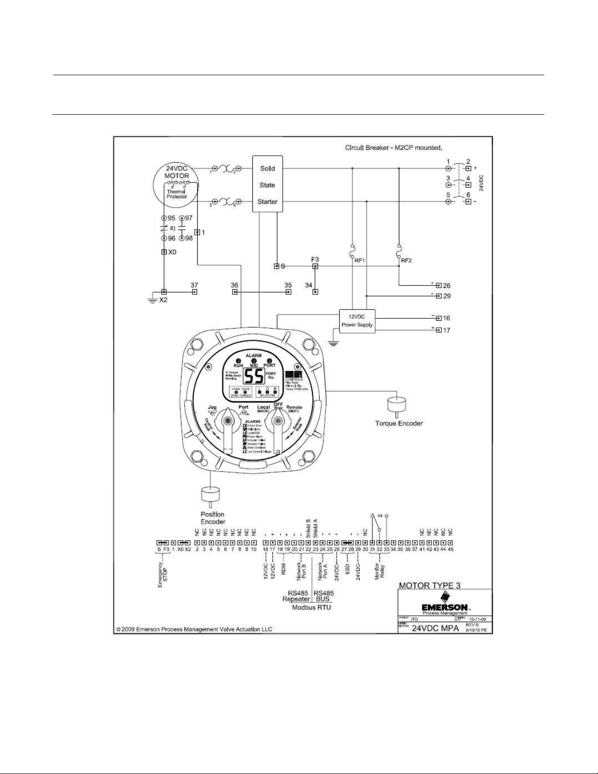
Multiport Flow Selector
April 2022
Figure 33. Wiring Diagram — 24VDC Power
Instruction Manual
D104239X012
54
Page 55

Instruction Manual
D104239X012
Multiport Flow Selector
April 2022
55
Page 56

Multiport Flow Selector
April 2022
Instruction Manual
D104239X012
Neither Emerson, Emerson Automation Solutions, nor any of their affiliated entities assumes responsibility for the selection, use or maintenance
of any product. Responsibility for proper selection, use, and maintenance of any product remains solely with the purchaser and end user.
Fisher and Bettis are marks owned by one of the companies in the Emerson Automation Solutions business unit of Emerson Electric Co. Emerson
Automation Solutions, Emerson, and the Emerson logo are trademarks and service marks of Emerson Electric Co. All other marks are the property of their
respective owners.
The contents of this publication are presented for informational purposes only, and while every effort has been made to ensure their accuracy, they are not
to be construed as warranties or guarantees, express or implied, regarding the products or services described herein or their use or applicability. All sales are
governed by our terms and conditions, which are available upon request. We reserve the right to modify or improve the designs or specifications of such
products at any time without notice.
Emerson Automation Solutions
Marshalltown, Iowa 50158 USA
Sorocaba, 18087 Brazil
Cernay, 68700 France
Dubai, United Arab Emirates
Singapore 128461 Singapore
www.Fisher.com
56
E 2018, 2022 Fisher Controls International LLC. All rights reserved.
 Loading...