

Controllore di livello digitale FIELDVUE DLC3010 Fisher (DLC3010 Digital Level Controller) (Italian) (Supported Product)
Fisher Controllore di livello digitale FIELDVUE DLC3010 Fisher (DLC3010 Digital Level Controller) (Italian) (Supported Product) Quick Start Guide [it]

Quick Start Guide
D103214X0IT
DLC3010 Digital Level Controller
May 2022
Controllore di livello digitale FIELDVUE
DLC3010 Fisher
™
(DLC3010 Digital Level Controller)
(Supported Product)
Introduction 1.................................
Safety Instructions 1............................
Specifications 2................................
Inspection and Maintenance Schedules 2...........
Parts Ordering 2................................
Installation 3..................................
Operation 4...................................
Maintenance 5.................................
Non‐Fisher (OEM) Instruments, Switches, and
Accessories 6..................................
Latest Published Quick Start Guide 7...............
Introduction
™
The product covered in this document is no longer in production. This document, which includes the latest published
version of the quick start guide, is made available to provide updates of newer safety procedures. Be sure to follow the
safety procedures in this supplement as well as the specific instructions in the included quick start guide.
For more than 30 years, Fisher products have been manufactured with asbestos‐free components. The included quick
start guide might mention asbestos containing parts. Since 1988, any gasket or packing which may have contained
some asbestos, has been replaced by a suitable non‐asbestos material. Replacement parts in other materials are
available from your sales office.
Safety Instructions
Please read these safety warnings, cautions, and instructions carefully before using the product.
These instructions cannot cover every installation and situation. Do not install, operate, or maintain this
product without being fully trained and qualified in valve, actuator and accessory installation, operation
and maintenance. To avoid personal injury or property damage it is important to carefully read,
understand, and follow all of the contents of this manual, including all safety cautions and warnings. If
you have any questions about these instructions, contact your Emerson sales office before proceeding.
www.Fisher.com

DLC3010 Digital Level Controller
May 2022
Quick Start Guide
D103214X0IT
Specifications
This product was intended for a specific range of service conditions‐‐pressure, pressure drop, process and ambient
temperature, temperature variations, process fluid, and possibly other specifications. Do not expose the product to
service conditions or variables other than those for which the product was intended. If you are not sure what these
conditions or variables are, contact your Emerson sales office
other pertinent information that you have available.
for assistance. Provide the product serial number and all
Inspection and Maintenance Schedules
All products must be inspected periodically and maintained as needed. The schedule for inspection can only be
determined based on the severity of your service conditions. Your installation might also be subject to inspection
schedules set by applicable governmental codes and regulations, industry standards, company standards, or plant
standards.
In order to avoid increasing dust explosion risk, periodically clean dust deposits from all equipment.
When equipment is installed in a hazardous area location (potentially explosive atmosphere), prevent sparks by proper
tool selection and avoiding other types of impact energy.
Parts Ordering
Whenever ordering parts for older products, always specify the serial number of the product and provide all other
pertinent information that you can, such as product size, part material, age of the product, and general service
conditions. If you have modified the product since it was originally purchased, include that information with your
request.
WARNING
Use only genuine Fisher replacement parts. Components that are not supplied by Emerson should not, under any
circumstances, be used in any Fisher product. Use of components not supplied by Emerson may void your warranty, might
adversely affect the performance of the product and could result in personal injury and property damage.
2

Quick Start Guide
D103214X0IT
DLC3010 Digital Level Controller
May 2022
Installation
WARNING
Avoid personal injury or property damage from sudden release of process pressure or bursting of parts. Before mounting
the product:
D Do not install any system component where service conditions could exceed the limits given in this manual or the limits
on the appropriate nameplates. Use pressure‐relieving devices as required by government or accepted industry codes
and good engineering practices.
D Always wear protective gloves, clothing, and eyewear when performing any installation operations.
D Do not remove the actuator from the valve while the valve is still pressurized.
D Disconnect any operating lines providing air pressure, electric power, or a control signal to the actuator. Be sure the
actuator cannot suddenly open or close the valve.
D Use bypass valves or completely shut off the process to isolate the valve from process pressure. Relieve process pressure
from both sides of the valve.
D Vent the pneumatic actuator loading pressure and relieve any actuator spring precompression so the actuator is not
applying force to the valve stem; this will allow for the safe removal of the stem connector.
D Use lock‐out procedures to be sure that the above measures stay in effect while you work on the equipment.
D The instrument is capable of supplying full supply pressure to connected equipment. To avoid personal injury and
equipment damage, caused by sudden release of process pressure or bursting of parts, make sure the supply pressure
never exceeds the maximum safe working pressure of any connected equipment.
D Severe personal injury or property damage may occur from an uncontrolled process if the instrument air supply is not
clean, dry and oil‐free, or noncorrosive gas. While use and regular maintenance of a filter that removes particles larger
than 40 microns will suffice in most applications, check with an Emerson field office and Industry Instrument air quality
standards for use with corrosive gas or if you are unsure about the proper amount or method of air filtration or filter
maintenance.
D For corrosive media, make sure the tubing and instrument components that contact the corrosive media are of suitable
corrosion-resistant material. The use of unsuitable materials might result in personal injury or property damage due to
the uncontrolled release of the corrosive media.
D If natural gas or other flammable or hazardous gas is to be used as the supply pressure medium and preventive
measures are not taken, personal injury and property damage could result from fire or explosion of accumulated gas or
from contact with hazardous gas. Preventive measures may include, but are not limited to: Remote venting of the unit,
re‐evaluating the hazardous area classification, ensuring adequate ventilation, and the removal of any ignition sources.
D To avoid personal injury or property damage resulting from the sudden release of process pressure, use a high‐pressure
regulator system when operating the controller or transmitter from a high‐pressure source.
The instrument or instrument/actuator assembly does not form a gas‐tight seal, and when the assembly is in an
enclosed area, a remote vent line, adequate ventilation, and necessary safety measures should be used. Vent line piping
should comply with local and regional codes and should be as short as possible with adequate inside diameter and few
bends to reduce case pressure buildup. However, a remote vent pipe alone cannot be relied upon to remove all
hazardous gas, and leaks may still occur.
D Personal injury or property damage can result from the discharge of static electricity when flammable or hazardous
gases are present. Connect a 14 AWG (2.08 mm
flammable or hazardous gases are present. Refer to national and local codes and standards for grounding
requirements.
D Personal injury or property damage caused by fire or explosion may occur if electrical connections are attempted in an
area that contains a potentially explosive atmosphere or has been classified as hazardous. Confirm that area
classification and atmosphere conditions permit the safe removal of covers before proceeding.
D Personal injury or property damage, caused by fire or explosion from the leakage of flammable or hazardous gas, can
result if a suitable conduit seal is not installed. For explosion‐proof applications, install the seal no more than 457 mm
(18 inches) from the instrument when required by the nameplate. For ATEX applications use the proper cable gland
certified to the required category. Equipment must be installed per local and national electric codes.
D Check with your process or safety engineer for any additional measures that must be taken to protect against process
media.
2
) ground strap between the instrument and earth ground when
3

DLC3010 Digital Level Controller
May 2022
D If installing into an existing application, also refer to the WARNING in the Maintenance section.
Quick Start Guide
D103214X0IT
Special Instructions for Safe Use and Installations in Hazardous Locations
Certain nameplates may carry more than one approval, and each approval may have unique installation requirements
and/or conditions of safe use. Special instructions are listed by agency/approval. To get these instructions, contact
Emerson sales office
WARNING
Failure to follow conditions of safe use could result in personal injury or property damage from fire or explosion, or area
re‐classification.
. Read and understand these special conditions of use before installing.
Operation
With instruments, switches, and other accessories that are controlling valves or other final control elements, it is
possible to lose control of the final control element when you adjust or calibrate the instrument. If it is necessary to
take the instrument out of service for calibration or other adjustments, observe the following warning before
proceeding.
WARNING
Avoid personal injury or equipment damage from uncontrolled process. Provide some temporary means of control for the
process before taking the instrument out of service.
4

Quick Start Guide
D103214X0IT
DLC3010 Digital Level Controller
May 2022
Maintenance
WARNING
Avoid personal injury or property damage from sudden release of process pressure or bursting of parts. Before performing
any maintenance operations on an actuator‐mounted instrument or accessory:
D Always wear protective gloves, clothing, and eyewear.
D Provide some temporary measure of control to the process before taking the instrument out of service.
D Provide a means of containing the process fluid before removing any measurement devices from the process.
D Disconnect any operating lines providing air pressure, electric power, or a control signal to the actuator. Be sure the
actuator cannot suddenly open or close the valve.
D Use bypass valves or completely shut off the process to isolate the valve from process pressure. Relieve process pressure
from both sides of the valve.
D Vent the pneumatic actuator loading pressure and relieve any actuator spring precompression so the actuator is not
applying force to the valve stem; this will allow for the safe removal of the stem connector.
D Use lock‐out procedures to be sure that the above measures stay in effect while you work on the equipment.
D Check with your process or safety engineer for any additional measures that must be taken to protect against process
media.
When using natural gas as the supply medium, or for explosion proof applications, the following warnings also apply:
D Remove electrical power before removing any housing cover or cap. Personal injury or property damage from fire or
explosion may result if power is not disconnected before removing the cover or cap.
D Remove electrical power before disconnecting any of the pneumatic connections.
D When disconnecting any of the pneumatic connections or any pressure retaining part, natural gas will seep from the
unit and any connected equipment into the surrounding atmosphere. Personal injury or property damage may result
from fire or explosion if natural gas is used as the supply medium and appropriate preventive measures are not taken.
Preventive measures may include, but are not limited to, one or more of the following: ensuring adequate ventilation
and the removal of any ignition sources.
D Ensure that all housing caps and covers are correctly installed before putting this unit back into service. Failure to do so
could result in personal injury or property damage from fire or explosion.
Instruments Mounted on Tank or Cage
WARNING
For instruments mounted on a tank or displacer cage, release trapped pressure from the tank and lower the liquid level to a
point below the connection. This precaution is necessary to avoid personal injury from contact with the process fluid.
5

DLC3010 Digital Level Controller
May 2022
Quick Start Guide
D103214X0IT
Instruments With a Hollow Displacer or Float
WARNING
For instruments with a hollow liquid level displacer, the displacer might retain process fluid or pressure. Personal injury
and property might result from sudden release of this pressure or fluid. Contact with hazardous fluid, fire, or explosion can
be caused by puncturing, heating, or repairing a displacer that is retaining process pressure or fluid. This danger may not
be readily apparent when disassembling the sensor or removing the displacer. A displacer that has been penetrated by
process pressure or fluid might contain:
D pressure as a result of being in a pressurized vessel
D liquid that becomes pressurized due to a change in temperature
D liquid that is flammable, hazardous or corrosive.
Handle the displacer with care. Consider the characteristics of the specific process liquid in use. Before removing the
displacer, observe the appropriate warnings provided in the sensor instruction manual.
Non‐Fisher (OEM) Instruments, Switches, and Accessories
Installation, Operation, and Maintenance
Refer to the original manufacturer's documentation for Installation, Operation and Maintenance safety information.
Neither Emerson, Emerson Automation Solutions, nor any of their affiliated entities assumes responsibility for the selection, use or maintenance
of any product. Responsibility for proper selection, use, and maintenance of any product remains solely with the purchaser and end user.
Fisher and FIELDVUE are marks owned by one of the companies in the Emerson Automation Solutions business unit of Emerson Electric Co. Emerson
Automation Solutions, Emerson, and the Emerson logo are trademarks and service marks of Emerson Electric Co. All other marks are the property of their
respective owners.
The contents of this publication are presented for informational purposes only, and while every effort has been made to ensure their accuracy, they are not
to be construed as warranties or guarantees, express or implied, regarding the products or services described herein or their use or applicability. All sales are
governed by our terms and conditions, which are available upon request. We reserve the right to modify or improve the designs or specifications of such
products at any time without notice.
Emerson Automation Solutions
Marshalltown, Iowa 50158 USA
Sorocaba, 18087 Brazil
Cernay, 68700 France
Dubai, United Arab Emirates
Singapore 128461 Singapore
www.Fisher.com
6
E 2022 Fisher Controls International LLC. All rights reserved.
Guida rapida
D103214X0IT
Controllore di livello digitale DLC3010
Luglio 2020
Controllore di livello digitale FIELDVUE
DLC3010 Fisher
Sommario
Installazione 2....................
Montaggio 8......................
Connessioni elettriche 13...........
Impostazione iniziale 18............
Taratura 23.......................
Schemi 28........................
Specifiche 29.....................
™
La presente guida rapida si riferisce a:
Tipo di apparecchiatura DLC3010
Revisione apparecchiatura 1
Revisione hardware 1
Revisione firmware 8
Revisione DD 3
™
W7977-2
Nota
La presente guida descrive le procedure di installazione, impostazione e calibrazione del DLC3010 tramite un comunicatore da
campo Emerson. Per ulteriori informazioni circa questo prodotto, tra cuimateriali di riferimento, informazioni sull'impostazione
manuale, procedure di manutenzione e dettagli sui pezzi di ricambio, fare riferimento al manuale di istruzioni del DLC3010
(D102748X012
sito web all'indirizzo www.Fisher.com.
Per informazioni relative all'uso del comunicatore da campo, consultare il manuale
Emerson Performance Technologies.
www.Fisher.com
). Qualora fosse necessaria una copia di questo documento, rivolgersi all'ufficio vendite Emerson o visitare il nostro
del comunicatore da campo disponibile tramite
Controllore di livello digitale DLC3010
Luglio 2020
Guida rapida
D103214X0IT
Installazione
AVVERTENZA
Per evitare infortuni, indossare sempre guanti, indumenti e occhiali di protezione durante qualsiasi intervento di
installazione.
In caso di perforazione, surriscaldamento o riparazioni eseguite su un dislocatore in cui è ancora presente pressione o fluido
di processo, sono possibili danni o infortuni provocati dal rilascio improvviso di pressione, da contatto con un fluido
pericoloso, incendi o esplosioni. Tale pericolo potrebbe non essere evidente durante lo smontaggio del sensore o la
rimozione del dislocatore. Prima di smontare il sensore o rimuovere il dislocatore, leggere le avvertenze pertinenti
riportate nel manuale di istruzioni del sensore.
Per informazioni su ulteriori misure di protezione dal fluido di processo rivolgersi all'ingegnere di processo o al
responsabile della sicurezza.
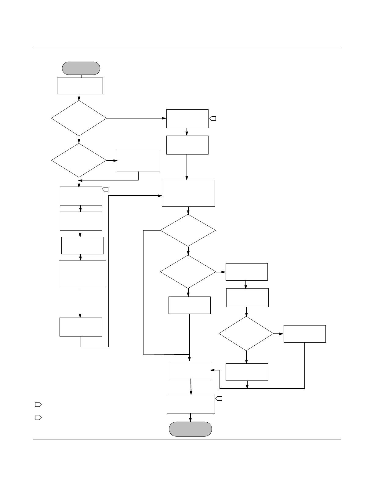
Questa sezione contiene informazioni sull'installazione del controllore di livello digitale e comprende un diagramma di flusso per
l'installazione (Figura 1), informazioni sul montaggio e sull'installazione elettrica e un paragrafo dedicato ai cavallotti della modalità
di guasto.
Prima di installare, azionare o effettuare la manutenzione di un controllore di livello digitale DLC3010, è necessario
ricevere un addestramento completo e qualificato per quanto riguarda la manutenzione, il funzionamento e
l'installazione di valvole, attuatori e accessori. Per evitare danni o infortuni, è fondamentale leggere attentamente e
comprendere il contenuto del presente manuale e seguirne tutte le indicazioni, inclusi tutti i messaggi di
avvertenza e di attenzione relativi alla sicurezza. In caso di domande relative alle presenti istruzioni, prima di
procedere contattare l’ufficio vendite Emerson
.
2
Guida rapida
D103214X0IT
Figura 1. Diagramma di flusso dell'installazione
INIZIO
Controllare la
posizione del
cavallotto di allarme
Controllore di livello digitale DLC3010
Luglio 2020
Montato in
fabbrica sul
sensore 249?
No
Applicazione
ad alta
temperatura?
No
Montare e cablare
il controllore di
livello digitale
Alimentare il
controllore di
livello digitale
Impostare lo
scostamento di
livello su zero
Usare l'impostazione
guidata per
immettere i dati del
sensore e le
condizioni di taratura
Sì
Sì
Installare il gruppo
dell'isolatore
1
termico
Cablare il
controllore di
livello digitale
Alimentare il
controllore di
livello digitale
Immettere targhetta,
messaggi, data e
controllare o impostare
i dati dell'applicazione
Sì
Misura di densità?
Si applica la
correzione di
temperatura?
Impostare il peso
specifico
target
No
No
1
Sì
Impostare le
unità di
temperatura
Impostare le
tabelle del peso
specifico
Tarare il
sensore
NOTA:
1 SE SI USA UNA TERMORESISTENZA RTD PER LA CORREZIONE DI
TEMPERATURA, COLLEGARE ANCHE LA TERMORESISTENZA RTD AL
CONTROLLORE DI LIVELLO DIGITALE
2 LA PROTEZIONE DA SCRITTURA È OPERATIVA SOLO SE IL
DLC3010 RIMANE ALIMENTATO
Impostare i
valori del
campo di lavoro
Protezione da
scrittura
FINE
Si usa una
termoresistenza
Immettere la
temperatura di
2
RTD?
No
processo
Sì
Impostare e tarare
la termoresistenza
RTD
3

Controllore di livello digitale DLC3010
Luglio 2020
Guida rapida
D103214X0IT
Configurazione: al banco o nel circuito
Configurare il controllore di livello digitale prima o dopo l'installazione. Potrebbe essere utile configurare lo strumento al banco
prima dell'installazione per assicurarsi che funzioni correttamente e per familiarizzarsi con le sue funzionalità.
Protezione del giunto di accoppiamento e dei bloccaggi
delle leve
ATTENZIONE
Danni ai bloccaggi delle leve e ad altri componenti possono causare errori di misura. Per spostare il sensore e il controllore
attenersi alle seguenti istruzioni.
Bloccaggio della leva
Il bloccaggio della leva è integrato nella maniglia di accesso al giunto di accoppiamento. Quando la maniglia è aperta, la leva è
bloccata nella posizione di folle per il giunto di accoppiamento. In alcuni casi, questa funzione è usata per proteggere il gruppo
della leva da movimenti bruschi durante la spedizione.
Al momento della consegna il controllore DLC3010 presenta una delle seguenti configurazioni meccaniche:
1. Un sistema di dislocatore con gabbia accoppiato e completamente assemblato è spedito con il dislocatore o l'asta di
azionamento bloccati tramite mezzi meccanici entro il campo operativo. In questo caso la maniglia di accesso (Figura 2) sarà in
posizione sbloccata. Prima di eseguire la taratura rimuovere i mezzi usati per bloccare il dislocatore (consultare il manuale di
istruzioni del sensore pertinente). Il giunto di accoppiamento deve essere integro.
Figura 2. Comparto di connessione del sensore (anello adattatore rimosso per maggiore chiarezza)
PRIGIONIERI DI
MONTAGGIO
FORO DI ACCESSO
MORSETTO DELL'ALBERO
VITE DI FERMO
PREMERE IN QUESTO
PUNTO PER SPOSTARE
LA MANIGLIA DI
ACCESSO
FARE SCORRERE LA MANIGLIA DI
ACCESSO VERSO LA PARTE
ANTERIORE DELL'UNITÀ PER
ESPORRE IL FORO DI ACCESSO
4

Guida rapida
D103214X0IT
Controllore di livello digitale DLC3010
Luglio 2020
ATTENZIONE
In caso di spedizione di uno strumento montato su un sensore, se il gruppo della leva è accoppiato alla tiranteria e questa è
bloccata dai blocchi del dislocatore, l'uso del bloccaggio della leva può causare danni ai giunti del soffietto o al bloccaggio
della leva.
2. Se il dislocatore non può essere bloccato a causa della configurazione della gabbia o per altri motivi, staccare il trasmettitore dal
tubo di torsione allentando il dado di accoppiamento e spostare la maniglia di accesso in posizione bloccata. Prima di rendere
operativa questa configurazione, eseguire la procedura di accoppiamento.
3. Per un sistema senza gabbia nel quale il dislocatore non è collegato al tubo di torsione durante la spedizione, è il tubo di torsione
stesso a stabilizzare la posizione della leva accoppiata appoggiando contro un nottolino di arresto nel sensore. La maniglia di
accesso sarà in posizione sbloccata. Montare il sensore e appendere il dislocatore. Il giunto di accoppiamento deve essere
integro.
4. Se il controllore è stato inviato separatamente, la maniglia di accesso sarà in posizione bloccata. È necessario eseguire tutte le
procedure di montaggio, accoppiamento e taratura.
La maniglia di accesso include una vite di tenuta, come mostrato nelle Figure 2 e 6. La vite è avvitata in modo da fare battuta con la
molla a balestra nel gruppo della maniglia prima della spedizione. In questo modo blocca la maniglia nella posizione desiderata
durante la spedizione e il funzionamento. Per impostare la maniglia di accesso su aperto o chiuso, la vite di tenuta deve essere
svitata in modo che la testa sia a livello con la superficie della maniglia.
Certificazioni per aree pericolose e istruzioni speciali per l'uso sicuro e
l'installazione in aree pericolose
Su alcune targhette dati può essere riportata più di una certificazione e ciascuna certificazione può comportare specifici requisiti di
installazione e/o condizioni per l'uso sicuro. Queste istruzioni speciali per l'uso sicuro sono in aggiunta a, e possono sostituire, le
procedure di installazione standard. Le istruzioni speciali sono elencate per tipo di certificazione.
Nota
Queste informazioni completano le marcature sulla targhetta dati applicata al prodotto.
Per identificare le certificazioni, fare sempre riferimento alla targhetta dati. Per ulteriori informazioni su certificazioni non riportate
qui, contattare l'ufficio vendite Emerson
AVVERTENZA
La mancata osservanza di queste condizioni per l'uso sicuro può essere causa di infortuni o danni causati da incendi o
esplosioni e di riclassificazione dell'area.
CSA
Condizioni speciali per l'uso sicuro
A sicurezza intrinseca, a prova di esplosione, Divisione 2, a prova di accensione per polveri
Temperatura ambiente nominale: -40 _C ≤ Ta ≤ +80 _C; -40 _C ≤ Ta ≤ +78 _C; -40 _C ≤ Ta ≤ +70 _C
Fare riferimento alla Tabella 1 per informazioni sulla certificazione.
.
5
Controllore di livello digitale DLC3010
Luglio 2020
Guida rapida
D103214X0IT
Tabella 1. Certificazioni per aree pericolose - CSA (Canada)
Organismo di
certificazione
CSA
Ex ia, a sicurezza intrinseca
Classe I, Divisione 1, 2, Gruppi A, B, C, D
Classe II, Divisione 1, 2, Gruppi E, F, G
Classe III
T6 in conformità al disegno 28B5744 (Figura 13)
A prova di esplosione
Classe I, Divisione 1, Gruppi B, C, D T5/T6
Classe I, Divisione 2, Gruppi A, B, C, D T5/T6 - - -
Classe II, Divisione 1, 2, Gruppi E, F, G T5/T6
Classe III T5/T6
Certificazione ottenuta Valori nominali Codice di temperatura
Vmax = 30 V c.c.
Imax = 226 mA
Ci = 5,5 nF
Li = 0,4 mH
- - -
- - -
T6 (Tamb ≤ 80 °C)
T5 (Tamb ≤ 80 °C)
T6 (Tamb ≤ 78 °C)
T5 (Tamb ≤ 80 °C)
T6 (Tamb ≤ 70 °C)
T5 (Tamb ≤ 80 °C)
T6 (Tamb ≤ 78 °C)
FM
Condizioni speciali per l'uso sicuro
A sicurezza intrinseca, a prova di esplosione, a prova di accensione, a prova di accensione per polveri
1. La custodia dell'apparecchio contiene alluminio e costituisce un potenziale rischio di ignizione causata da urti o attrito. Durante
l'installazione e l'utilizzo prestare attenzione a evitare urti o attrito.
Fare riferimento alla Tabella 2 per informazioni sulla certificazione.
Tabella 2. Certificazioni per aree pericolose - FM (Stati Uniti)
Organismo di
certificazione
FM
SI a sicurezza intrinseca
Classe I,II,III, Divisione 1, Gruppi A,B,C,D,
E,F,G T5 secondo il disegno 28B5745 (Figura 14)
XP a prova di esplosione
Classe I, Divisione 1, Gruppi B, C, D T5
NI a prova di accensione
Classe I, Divisione 2, Gruppi A, B, C, D T5
DIP a prova di accensione per polveri
Classe II, Divisione 1, Gruppi E, F, G T5
S adatto per l'uso
Classe II, III, Divisione 2, Gruppi F, G
Certificazione ottenuta Valori nominali Codice di temperatura
Vmax = 30 V c.c.
Imax = 226 mA
Ci = 5,5 nF
Li = 0,4 mH
Pi = 1,4 W
- - - T5 (Tamb ≤ 80 °C)
T5 (Tamb ≤ 80 °C)
ATEX
Condizioni speciali per l'uso sicuro
A sicurezza intrinseca
Il DLC3010 è un apparecchio a sicurezza intrinseca; può essere montato in aree pericolose.
Questo apparecchio può essere collegato esclusivamente ad apparecchiature dotate di certificazione di sicurezza intrinseca e la
combinazione deve essere compatibile con le regole per la sicurezza intrinseca.
L'elettronica di questo prodotto è isolata dalla custodia/terra.
Temperatura ambiente operativa: da -40 _C a +80 _C
A prova di fiamma
Temperatura ambiente operativa: da -40 _C a + 80 _C
L'apparecchio deve essere dotato di entrata cavi con certificazione Ex d IIC.
6
Guida rapida
D103214X0IT
Controllore di livello digitale DLC3010
Luglio 2020
Tipo n
Questa apparecchiatura deve essere usata con un'entrata cavi che garantisca una protezione minima pari a IP66 e conforme agli
standard europei applicabili.
Temperatura ambiente operativa: da -40 _C a + 80 _C
Fare riferimento alla Tabella 3 per ulteriori informazioni relative alla certificazione.
Tabella 3. Certificazioni per aree pericolose - ATEX
Certificato Certificazione ottenuta Valori nominali Codice di temperatura
ATEX
A sicurezza intrinseca
II 1 G D
Gas
Ex ia IIC T5 Ga
A prova di polvere
Ex ia IIIC T83 °C Da IP66
A prova di fiamma
II 2 G D
Gas
Ex d IIC T5 Gb
A prova di polvere
Ex tb IIIC T83 °C Db IP66
Tipo n
II 3 G D
Gas
Ex nA IIC T5 Gc
A prova di polvere
Ex t IIIC T83 °C Dc IP66
Ui = 30 V c.c.
Ii = 226 mA
Pi = 1,2 W
Ci = 5,5 nF
Li = 0,4 mH
T5 (Tamb ≤ 80 °C)
- - - T5 (Tamb ≤ 80 °C)
- - - T5 (Tamb ≤ 80 °C)
IECEx
A sicurezza intrinseca
Questo apparato può essere collegato esclusivamente ad apparecchiature dotate di certificazione di sicurezza intrinseca e la
combinazione deve essere compatibile con le regole per la sicurezza intrinseca.
L'elettronica di questo prodotto è isolata dalla custodia/terra.
Temperatura ambiente di esercizio: da -40 _C a + 80 _C
A prova di fiamma, tipo n
Nessuna condizione speciale per l'uso sicuro.
Fare riferimento alla Tabella 4 per informazioni sulla certificazione.
Tabella 4. Certificazioni per aree pericolose - IECEx
Certificato Certificazione ottenuta Valori nominali Codice di temperatura
IECEx
A sicurezza intrinseca
Gas
Ex ia IIC T5 Ga
A prova di polvere
Ex ia IIIC T83 °C Da IP66
A prova di fiamma
Gas
Ex d IIC T5 Gb
A prova di polvere
Ex t IIIC T83 °C Db IP66
Tipo n
Gas
Ex nA IIC T5 Gc
A prova di polvere
Ex t IIIC T83 °C Dc IP66
Ui = 30 V c.c.
Ii = 226 mA
Pi = 1,2 W
Ci = 5,5 nF
Li = 0,4 mH
T5 (Tamb ≤ 80 °C)
- - - T5 (Tamb ≤ 80 °C)
- - - T5 (Tamb ≤ 80 °C)
7

Controllore di livello digitale DLC3010
Luglio 2020
Guida rapida
D103214X0IT
Montaggio
Montaggio del sensore 249
Il sensore 249 può essere montato in due modi diversi, a seconda del tipo di sensore. Se il sensore è dotato di un dislocatore con
gabbia, la posizione tipica di montaggio è sul lato del serbatoio (Figura 3). Se il sensore è dotato di un dislocatore senza gabbia, la
posizione tipica di montaggio è sul lato o sulla sommità del serbatoio (Figura 4).
Figura 3. Posizione di montaggio tipica del sensore
con gabbia
LIVELLO DEL
LIQUIDO
Figura 4. Posizione di montaggio tipica del sensore
senza gabbia
Il controllore di livello digitale DLC3010 è normalmente spedito collegato al sensore. Se ordinato separatamente, può essere
conveniente montare il controllore di livello digitale sul sensore ed eseguire l'impostazione iniziale e la taratura prima di installare il
sensore sul serbatoio.
Nota
I sensori con gabbia presentano un'asta e un blocco installati su ciascuna estremità del dislocatore, per proteggere il dislocatore
durante la spedizione. Prima di installare il sensore, rimuovere questi componenti in modo che il dislocatore possa funzionare
correttamente.
8

Guida rapida
D103214X0IT
Controllore di livello digitale DLC3010
Luglio 2020
Orientamento del DLC3010
Montare il controllore di livello digitale in modo che il foro di accesso al morsetto della barra di torsione (Figura 2) sia rivolto verso il
basso, per favorire il drenaggio dell'umidità accumulata.
Nota
Se l'utente fornisce uno scarico alternativo e una piccola perdita di prestazione può considerarsi accettabile, lo strumento può
essere montato ruotandolo a incrementi di 90 gradi attorno all'asse dell'albero pilota. Per facilitare tale procedura, l'indicatore LCD
può essere ruotato a incrementi di 90 gradi.
Il controllore di livello digitale e il braccio del tubo di torsione possono essere collegati al sensore sia a destra che a sinistra del
dislocatore (Figura 5). Tale configurazione può essere modificata sul campo su un sensore 249 (fare riferimento al manuale di
istruzioni del sensore pertinente). La modifica del montaggio comporta anche il cambiamento dell'azione effettiva, in quanto la
rotazione del tubo di torsione per aumentare il livello (osservando l'estremità sporgente dell'albero) avviene in senso orario se
l'unità è montata a destra del dislocatore e in senso antiorario se l'unità è montata a sinistra del dislocatore.
Tutti i sensori con gabbia 249 sono dotati di una testa rotante. Il controllore di livello digitale può quindi essere posizionato in una
delle otto posizioni alternative attorno alla gabbia, come indicato dai numeri da 1 a 8 nella Figura 5. Per ruotare la testa, rimuovere
i bulloni della flangia della testa e i dadi e spostare la testa nella posizione desiderata.
Montaggio del controllore di livello digitale su un sensore 249
Se non altrimenti indicato, fare riferimento alla Figura 2.
1. Se la vite di fermo nella maniglia di accesso è avvitata contro la molla a balestra, svitarla con una chiave esagonale da 2 mm in
modo che la testa della vite sia a livello con la superficie esterna della maniglia (Figura 6). Spostare la maniglia di accesso in
posizione bloccata in modo da esporre il foro di accesso. Premere sulla parte posteriore della maniglia, come mostrato nella
Figura 2, quindi spostare la maniglia verso la parte anteriore dell'unità. Verificare che la maniglia di bloccaggio si innesti nel
fermo.
2. Allentare il morsetto dell'albero inserendo una chiave a bussola da 10 mm nel foro di accesso (Figura 2). Questo morsetto sarà
serrato nuovamente durante la fase di accoppiamento delle istruzioni riportate nella sezione Impostazione iniziale.
3. Rimuovere i dadi esagonali dai prigionieri di montaggio. Non rimuovere l'anello adattatore.
AVVERTENZA
Se il gruppo del tubo di torsione viene piegato o disallineato durante l'installazione, si possono verificare errori di misura.
9

Controllore di livello digitale DLC3010
Luglio 2020
Guida rapida
D103214X0IT
Figura 5. Posizioni tipiche di montaggio del controllore di livello digitale FIELDVUE DLC3010 su un sensore 249 Fisher
SENSORE
CON
GABBIA
SENZA
GABBIA
A SINISTRA DEL DISLOCATORE
7
1
5
3
A DESTRA DEL DISLOCATORE
3
6
1
4
8
1
2
7
5
1
2
8
4
6
1 Non disponibile per 249C e 249K.
Figura 6. Dettaglio della vite di fermo
VITE DI FERMO
4. Posizionare il controllore di livello digitale in modo che il foro di accesso si trovi sulla parte inferiore dello strumento.
5. Infilare con cautela i prigionieri di montaggio nei fori di montaggio del sensore in modo che il controllore di livello digitale si
adatti con precisione al sensore.
6. Installare nuovamente i dadi esagonali sui prigionieri di montaggio e serrarli a una coppia di 10 N·m (88.5 lbf-in.).
10

Guida rapida
D103214X0IT
Controllore di livello digitale DLC3010
Luglio 2020
Montaggio del controllore di livello digitale per applicazioni a
temperature estreme
Se non altrimenti indicato, fare riferimento alla Figura 7 per l'identificazione dei componenti.
Se la temperatura supera i limiti indicati nella Figura 8, è necessario usare un gruppo isolatore con il controllore di livello digitale.
Se con il sensore 249 viene usato un gruppo isolatore, è necessario usare una prolunga della barra di torsione.
Figura 7. Montaggio del controllore di livello digitale sul sensore in applicazioni a temperatura elevata
ISOLATORE
(RIF. 57)
PROLUNGA
VITI DI
FERMO
(RIF. 60)
GIUNTO DI
ACCOPPIAMENTO
DELL'ALBERO (RIF. 59)
RONDELLA
(RIF. 78)
DADI
ESAGONALI
(RIF. 34)
DELL'ALBERO
(RIF. 58)
VITI (RIF. 63)
MN28800
20A7423-C
B2707
SENSORE
PRIGIONIERI DI
MONTAGGIO (RIF. 33)
Figura 8. Linee guida per l'uso del gruppo isolatore termico opzionale
-40 -30
800
-20 -10
010 20
30 40 50 60
TEMPERATURA AMBIENTE (_C)
ISOLATORE TERMICO
400
ISOLATORE TERMICO NON NECESSARIO
0
1
TROPPO
FREDDO
-325
TEMPERATURA DI PROCESSO (_F)
0 20 40 60 80 100 120 140 160
-20-40
RICHIESTO
ISOLATORE TERMICO RICHIESTO
TEMPERATURA AMBIENTE (_F)
TRASMETTITORE STANDARD
NOTE:
1 PER TEMPERATURE DI PROCESSO INFERIORI A -29 _C (-20 _F) E SUPERIORI A 204 _C (400 _F) I MATERIALI DEL
SENSORE DEVONO ESSERE IDONEI AL PROCESSO - FARE RIFERIMENTO ALLA TABELLA 9.
2. SE IL PUNTO DI RUGIADA AMBIENTE È SUPERIORE ALLA TEMPERATURA DI PROCESSO, LA FORMAZIONE DI GHIAC
CIO PUÒ CAUSARE MALFUNZIONAMENTI DELLO STRUMENTO E RIDURRE L'EFFICACIA DELL'ISOLATORE.
39A4070-B
A5494-1
70
TROPPO
CALDO
80
176
425
400
300
200
100
0
-100
-200
TEMPERATURA DI PROCESSO (_C)
CONTROLLORE DI LIVELLO DIGITALE
ATTENZIONE
Se il gruppo del tubo di torsione viene piegato o disallineato durante l'installazione, si possono verificare errori di misura.
11

Controllore di livello digitale DLC3010
Luglio 2020
1. Per il montaggio del controllore di livello digitale su un sensore 249, fissare la prolunga dell'albero alla barra di torsione del sensore
tramite il giunto di accoppiamento dell'albero e le viti di fermo. Il giunto di accoppiamento deve essere centrato (Figura 7).
2. Spostare la maniglia di accesso in posizione bloccata in modo da esporre il foro di accesso. Premere sulla parte posteriore della
maniglia, come mostrato nella Figura 2, quindi spostare la maniglia verso la parte anteriore dell'unità. Verificare che la maniglia
di bloccaggio si innesti nel fermo.
3. Rimuovere i dadi esagonali dai prigionieri di montaggio.
4. Posizionare l'isolatore sul controllore di livello digitale, infilando l'isolatore perpendicolarmente sui prigionieri di montaggio.
5. Installare nuovamente i quattro dadi esagonali sui prigionieri di montaggio e serrare i dadi.
6. Infilare con cautela il controllore di livello digitale, con l'isolatore installato, sul giunto di accoppiamento dell'albero, in modo che
il foro di accesso si trovi sulla parte inferiore del controllore di livello digitale.
7. Fissare il controllore di livello digitale e l'isolatore al braccio del tubo di torsione con quattro viti.
8. Serrare le viti a una coppia di 10 N·m (88.5 lbf-in.).
Guida rapida
D103214X0IT
Accoppiamento
Se l'operazione non è ancora stata effettuata, eseguire la seguente procedura per accoppiare il controllore di livello digitale al
sensore.
1. Spostare la maniglia di accesso in posizione bloccata in modo da esporre il foro di accesso. Premere sulla parte posteriore della
maniglia, come mostrato nella Figura 2, quindi spostare la maniglia verso la parte anteriore dell'unità. Verificare che la maniglia
di bloccaggio si innesti nel fermo.
2. Impostare il dislocatore sulla condizione di processo più bassa (per esempio sul livello dell'acqua più basso o sul peso specifico
minimo), oppure sostituire il dislocatore con il peso di taratura più pesante.
Nota
Le applicazioni di interfaccia o densità con dislocatore/tubo di torsione di dimensioni adatte a una variazione totale della densità
relativa bassa prevedono l'uso del dislocatore costantemente sommerso. In tali applicazioni l'asta di torsione è talvolta appoggiata
su un fermo quando il dislocatore è asciutto. Il tubo di torsione comincia a spostarsi solo dopo che il dislocatore è stato coperto da
una quantità di liquido considerevole. In questo caso, effettuare l'accoppiamento con il dislocatore immerso nel fluido con la
densità minima e temperatura di processo massima, o con una condizione equivalente simulata con pesi calcolati.
Se le dimensioni del sensore risultano essere in una banda proporzionale superiore al 100% (campo di rotazione totale previsto
superiore a 4,4 gradi), accoppiare il trasmettitore all'albero pilota a una condizione di processo del 50%, in modo da utilizzare al
massimo la corsa disponibile del trasmettitore (
galleggiabilità zero (o galleggiabilità a differenziale zero).
3. Inserire una chiave a bussola da 10 mm nel foro di accesso e sul dado del morsetto della barra di torsione. Serrare il dato del
morsetto a una coppia massima di 2,1 N·m (18 lbf-in.).
4. Sbloccare la maniglia di accesso (premere sulla parte posteriore della maniglia come mostrato nella Figura 2, quindi spostare la
maniglia verso la parte posteriore dell'unità). La maniglia di bloccaggio deve innestarsi nel fermo.
$6_). La procedura di cattura di zero viene sempre effettuata in condizioni di
12

Guida rapida
D103214X0IT
Controllore di livello digitale DLC3010
Luglio 2020
Connessioni elettriche
AVVERTENZA
Selezionare il cablaggio e/o i pressacavi adatti per l'ambiente di utilizzo (aree pericolose, protezione di ingresso e
temperatura). Il mancato utilizzo di cablaggio e/o pressacavi adatti può causare infortuni o danni dovuti a incendi o
esplosioni.
Le connessioni elettriche devono essere conformi alle normative vigenti per la certificazione per aree pericolose
applicabile. Il mancato rispetto dei requisiti può causare danni o infortuni a seguito di un incendio o di un'esplosione.
Per evitare errori causati da rumori elettrici, l'installazione dei componenti elettrici deve essere effettuata nel modo corretto.
Nel circuito deve essere presente una resistenza compresa tra 230 e 600 Ω per la comunicazione con un comunicatore da campo.
Per le connessioni del circuito di corrente, fare riferimento alla Figura 9.
Figura 9. Collegamento di un comunicatore da campo al circuito del controllore di livello digitale
NOTA:
1 QUESTO RAPPRESENTA LA RESISTENZA DEL CIRCUITO IN SERIE TOTALE.
E0363
230 RL 600
Un comunicatore da campo
può essere collegato a
qualsiasi punto terminale del
circuito di segnale, tranne che
attraverso l'alimentazione.
Per la comunicazione, il
circuito di segnale deve avere
un carico compreso tra 230 e
600 .
1
Indicatore di riferimento
per le operazioni di
+
taratura o monitoraggio.
L'indicatore può essere
un voltmetro
attraverso un
−
resistore da 250
o un amperometro.
−
+
Il segnale di circuito può essere messo a
terra in qualsiasi punto o lasciato flottante.
+
ALIMENTATORE
−
+
−
Alimentazione
Per comunicare con il controllore di livello digitale, è necessaria un'alimentazione di almeno 17,75 V c.c. L'alimentazione fornita ai
terminali del trasmettitore è determinata dalla tensione di alimentazione disponibile meno il prodotto tra la resistenza totale del
circuito e la corrente del circuito. La tensione di alimentazione disponibile non deve mai essere inferiore alla tensione di avviamento
(la tensione di avviamento corrisponde alla tensione di alimentazione disponibile minima richiesta per una data resistenza totale
del circuito). Per determinare la tensione di avviamento richiesta, fare riferimento alla Figura 10. Se si conosce la resistenza totale
13

Controllore di livello digitale DLC3010
Luglio 2020
Guida rapida
D103214X0IT
del circuito, è possibile determinare la tensione di avviamento. Se si conosce la tensione di alimentazione disponibile, è possibile
determinare la resistenza massima del circuito consentita.
Se la tensione di alimentazione scende sotto la tensione di avviamento durante la configurazione del trasmettitore, il trasmettitore
potrebbe fornire dati non corretti.
L'alimentazione c.c. deve fornire potenza con un'ondulazione inferiore al 2%. Il carico resistivo totale è la somma della resistenza dei
conduttori del segnale e della resistenza di carico del controllore, dell'indicatore o di qualsiasi altro componente incluso nel
circuito. La resistenza delle barriere per sicurezza intrinseca, se usate, deve essere inclusa.
Figura 10. Requisiti di alimentazione e resistenza di carico
Carico massimo = 43,5 X
(tensione di alimentazione disponibile - 12,0)
783
E0284
Carico ()
250
0
10 20 2515
12 30
TENSIONE DI AVVIAMENTO (V c.c.)
Campo di
esercizio
Cablaggio sul campo
AVVERTENZA
Per evitare danni o infortuni causati da incendi o esplosioni interrompere l'alimentazione allo strumento prima di
rimuovere il coperchio del controllore di livello digitale in aree con atmosfera potenzialmente esplosiva o classificate come
pericolose.
Nota
Per applicazioni a sicurezza intrinseca, fare riferimento alle istruzioni fornite dal produttore delle barriere.
L'alimentazione al controllore di livello digitale viene fornita tramite il cavo di segnale. Il cavo di segnale non necessita di
schermatura, tuttavia si consiglia di usare cavo bipolare twistato per ottenere i migliori risultati. Non fare passare un cavo di segnale
senza schermatura in un conduit o in una canalina aperta insieme al cavo di alimentazione, né vicino ad apparecchiature elettriche
pesanti. Se il controllore digitale si trova in un'atmosfera esplosiva, non rimuovere i coperchi del controllore di livello digitale quando
il circuito è sotto tensione, a meno che l'installazione non sia a sicurezza intrinseca. Evitare il contatto con conduttori e terminali. Per
alimentare il controllore di livello digitale, collegare il conduttore di alimentazione positivo al terminale + e il conduttore di
alimentazione negativo al terminale - (Figura 11).
14

Guida rapida
D103214X0IT
Figura 11. Morsettiera del controllore di livello digitale
Controllore di livello digitale DLC3010
Luglio 2020
CONNESSIONI DI PROVA
CONNESSIONE
DEL CONDUIT
DA 1/2 NPT
W8041
VISTA ANTERIORE
CONNESSIONI
DEL CIRCUITO
DA 4-20 mA
CONNESSIONI DELLA
TERMORESISTENZA RTD
CONNESSIONE A
TERRA INTERNA
CONNESSIONE
DEL CONDUIT
DA 1/2 NPT
CONNESSIONE A
TERRA ESTERNA
VISTA POSTERIORE
ATTENZIONE
Non applicare alimentazione di circuito attraverso i terminali T e +. Ciò potrebbe danneggiare irreparabilmente il resistore
di rilevamento da 1 nella morsettiera. Non applicare alimentazione di circuito attraverso i terminali Rs e -. Ciò potrebbe
danneggiare irreparabilmente il resistore di rilevamento da 50 nel modulo dell'elettronica.
Quando si eseguono i collegamenti ai morsetti a vite, si consiglia di usare un attrezzo di crimpatura. Serrare i serrafili in modo da
garantire un buon contatto. Non è richiesto alcun cablaggio di alimentazione aggiuntivo. Tutti i coperchi del controllore di livello
digitale devono essere completamente innestati per soddisfare i requisiti a prova di esplosione. Per le unità con certificazione ATEX,
la vite di fermo del coperchio della morsettiera deve innestarsi in una delle cavità nella morsettiera, sotto il coperchio della
morsettiera.
Messa a terra
AVVERTENZA
Un incendio o un'esplosione causati da una scarica di elettricità statica in presenza di gas pericolosi o infiammabili possono
provocare danni e infortuni. Se sono presenti gas pericolosi o infiammabili, collegare una piattina di messa a terra da
2,1 mm
standard e alle normative locali e nazionali.
Il controllore di livello digitale funziona con il circuito del segnale di corrente sia collegato a terra che flottante. Tuttavia, il rumore
aggiuntivo nei sistemi flottanti interferisce con numerosi tipi di lettori. Se il segnale risulta irregolare o rumoroso, la messa a terra a
punto singolo del circuito del segnale di corrente può risolvere il problema. Il miglior punto di messa a terra del circuito è il
terminale negativo dell'alimentazione. In alternativa, mettere a terra uno dei lati del lettore. Non mettere a terra il circuito del
segnale di corrente in più di un punto.
Cavo schermato
Le tecniche di messa a terra consigliate per i cavi schermati richiedono un punto di messa a terra singolo per lo schermo. È possibile
collegare lo schermo all'alimentazione o ai terminali di messa a terra, interni o esterni, della morsettiera dello strumento mostrata
nella Figura 11.
2
(14 AWG) fra il controllore di livello digitale e la massa. Per i requisiti di messa a terra, fare riferimento agli
15

Controllore di livello digitale DLC3010
Luglio 2020
Guida rapida
D103214X0IT
Connessioni del circuito di corrente/alimentazione
Usare un filo di rame di dimensione adeguata per garantire che la tensione attraverso i terminali del controllore di livello digitale
non scenda al di sotto di 12,0 V c.c. Collegare i conduttori del segnale di corrente come mostrato nella Figura 9. Dopo avere
effettuato le connessioni, controllare che siano state eseguite correttamente e che la polarità sia a sua volta corretta, quindi
attivare l'alimentazione.
Connessioni della termoresistenza RTD
Al controllore di livello digitale può essere collegata una termoresistenza RTD che rileva la temperatura di processo. Ciò permette
allo strumento di eseguire automaticamente correzioni del peso specifico in base alle variazioni di temperatura. Per ottenere i
migliori risultati, posizionare la termoresistenza RTD nel punto più vicino possibile al dislocatore. Per ottenere le migliori
prestazioni di compatibilità elettromagnetica, collegare la termoresistenza RTD con un cavo schermato non più lungo di 3 m
(9.8 ft). Collegare solo un'estremità della schermatura. Collegare la schermatura alla connessione a terra interna nella morsettiera
dello strumento o al pozzetto termometrico della termoresistenza RTD. Per collegare la termoresistenza RTD al controllore di
livello digitale attenersi alle seguenti istruzioni (Figura 11):
Connessioni della termoresistenza RTD a due fili
1. Collegare un cavallotto tra i terminali RS e R1 nella morsettiera.
2. Collegare la termoresistenza RTD ai terminali R1 e R2.
Nota
Nel corso dell'impostazione manuale, è necessario specificare la resistenza del cavo di collegamento per una RTD a 2 fili. Cavi da
250 piedi da 16 AWG hanno una resistenza di 1 Ω.
Connessioni della termoresistenza RTD a tre fili
1. Collegare i 2 fili collegati alla stessa estremità della termoresistenza RTD ai terminali RS e R1 nella morsettiera. Di solito questi fili
sono dello stesso colore.
2. Collegare il terzo filo al terminale R2 (la resistenza misurata tra questo filo e uno dei fili collegati al terminale RS o R1 deve essere
di valore equivalente alla resistenza per la temperatura ambiente effettiva. Fare riferimento alla tabella di conversione da
temperatura a resistenza del produttore della termoresistenza RTD). Di solito questo filo è di colore diverso rispetto ai fili
collegati ai terminali RS e R1.
Connessioni per la comunicazione
AVVERTENZA
Se questa connessione viene eseguita in un'area con atmosfera potenzialmente esplosiva o classificata come pericolosa,
possono verificarsi danni e infortuni in seguito a un incendio o a un'esplosione. Verificare che la classificazione dell'area e le
condizioni dell'atmosfera consentano la rimozione sicura del coperchio della morsettiera prima di procedere.
Il comunicatore da campo si interfaccia con il controllore di livello digitale DLC3010 da qualsiasi punto terminale del cablaggio nel
circuito da 4-20 mA (tranne che attraverso l'alimentazione). Se si decide di collegare il comunicatore HART
strumento, collegare il comunicatore ai terminali + e - del circuito all'interno della morsettiera in modo da ottenere una
comunicazione locale con lo strumento.
16
®
direttamente allo

Guida rapida
D103214X0IT
Controllore di livello digitale DLC3010
Luglio 2020
Cavallotto di allarme
Ciascun controllore di livello digitale controlla continuamente le proprie prestazioni durante il funzionamento normale. Questa
procedura di diagnostica automatica consiste in una serie di controlli temporizzati ripetuti continuamente. Se la diagnostica rileva
un guasto nell'elettronica, lo strumento regola la propria uscita a un valore inferiore a 3,70 mA o superiore a 22,5 mA, a seconda
della posizione (HI/LO, alto/basso) del cavallotto di allarme.
Una condizione di allarme si verifica quando il sistema di diagnostica automatica del controllore di livello digitale rileva un errore
che renderebbe la misura della variabile di processo imprecisa, incorretta o indefinita, oppure in caso di violazione di una soglia
definita dall'utente. A questo punto, l'uscita analogica dell'unità viene portata a un livello definito superiore o inferiore al campo
nominale di 4-20 mA, in base alla posizione del cavallotto di allarme.
Sull'elettronica incapsulata serie 14B5483X042 e precedenti, se il cavallotto non è presente, l'allarme è indeterminato, ma di solito
il comportamento corrisponde alla selezione FAIL LOW (Guasto basso). Sull'elettronica incapsulata 14B5484X052 e successivi, se il
cavallotto non è presente, il comportamento corrisponde alla selezione predefinita FAIL HIGH (Guasto alto).
Posizioni del cavallotto di allarme
Senza indicatore:
Il cavallotto di allarme è ubicato sul lato anteriore del modulo dell'elettronica, sul lato dell'elettronica della custodia del controllore
di livello digitale, ed è contrassegnato con la dicitura FAIL MODE (Modalità guasto).
Con indicatore:
Il cavallotto di allarme è ubicato sullo schermo LCD dell'elettronica, sul lato del modulo dell'elettronica della custodia del
controllore di livello digitale, ed è contrassegnato con la dicitura FAIL MODE (Modalità guasto).
Modifica della posizione del cavallotto
AVVERTENZA
Se la procedura descritta di seguito viene eseguita in un'area con atmosfera potenzialmente esplosiva o classificata come
pericolosa, possono verificarsi danni e infortuni in seguito a un incendio o a un'esplosione. Verificare che la classificazione
dell'area e le condizioni dell'atmosfera consentano la rimozione sicura del coperchio dello strumento prima di procedere.
Per modificare la posizione del cavallotto di allarme attenersi alla seguente procedura:
1. Se il controllore di livello digitale è installato, impostare il circuito in modalità manuale.
2. Rimuovere il coperchio della custodia sul lato dell'elettronica. Non rimuovere il coperchio in atmosfera esplosiva quando il
circuito è sotto tensione.
3. Regolare il cavallotto nella posizione desiderata.
4. Installare nuovamente il coperchio. Tutti i coperchi devono essere completamente innestati per soddisfare i requisiti a prova di
esplosione. Per le unità con certificazione ATEX, la vite di fermo sulla custodia del trasduttore deve innestarsi in una delle cavità
del coperchio.
17

Controllore di livello digitale DLC3010
Luglio 2020
Guida rapida
D103214X0IT
Accesso alle procedure di configurazione e taratura
Per le procedure che richiedono l'uso di un comunicatore da campo, sono indicati il percorso di menu e la sequenza di tasti
numerici necessari per visualizzare il menu del comunicatore desiderato.
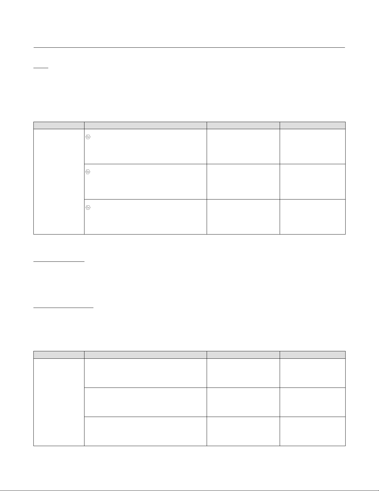
Per esempio, per accedere al menu Full Calibration (Taratura completa):
Comunicatore da campo Configure > Calibration > Primary > Full Calibration (2-5-1-1)
Nota
Le sequenze di tasti rapidi sono applicabili solo al comunicatore da campo 475. Non si applicano al comunicatore per dispositivi
Trex.
Configurazione e taratura
Impostazione iniziale
Se il controllore di livello digitale DLC3010 viene inviato dalla fabbrica montato su un sensore 249, l'impostazione iniziale e la
taratura non sono necessarie. I dati del sensore vengono immessi in fabbrica, lo strumento viene accoppiato al sensore e la
combinazione sensore-strumento viene tarata.
Nota
Se il controllore di livello digitale è montato sul sensore con il dislocatore bloccato, o se il dislocatore non è collegato, lo strumento
sarà accoppiato al sensore e il gruppo della leva sbloccato. Per mettere in servizio l'unità, in caso il dislocatore sia bloccato,
rimuovere l'asta e bloccare il dislocatore a entrambe le estremità, quindi controllare la taratura dello strumento (se è stata ordinata
l'opzione taratura di fabbrica, lo strumento verrà precompensato alle condizioni di processo indicate nell'ordine e potrebbe
risultare non tarato se confrontato con gli ingressi di livello dell'acqua allo 0 e al 100% della temperatura ambiente).
Se il dislocatore non è collegato, appenderlo al tubo di torsione.
Se il controllore di livello digitale è montato sul sensore e il dislocatore non è bloccato (come in un sistema montato su slitta), lo
strumento non sarà accoppiato al sensore e il gruppo della leva sarà bloccato. Prima di mettere in servizio l'unità, accoppiare lo
strumento al sensore, quindi sbloccare il gruppo della leva.
Una volta connesso e accoppiato correttamente il sensore al controllore di livello digitale, stabilire una condizione zero di processo
ed eseguire la procedura di taratura zero appropriata in Partial Calibration (Taratura parziale). La coppia nominale non deve essere
tarata nuovamente.
Per controllare i dati di configurazione immessi in fabbrica, collegare lo strumento a un'alimentazione da 24 V c.c. come mostrato
nella Figura 9. Collegare il comunicatore da campo allo strumento e accenderlo. Accedere a Configure (Configurazione) e quindi
controllare i dati in Manual Setup, Alert Setup, and Communications (Impostazione manuale, Impostazione allarme e
Comunicazioni). Se i dati dell'applicazione in uso sono stati modificati dopo la configurazione in fabbrica dello strumento, fare
riferimento alla sezione Impostazione manuale per istruzioni su come modificare i dati di configurazione.
Per strumenti non montati su un sensore di livello o quando si sostituisce uno strumento, l'impostazione iniziale consiste
nell'immissione dei dati del sensore. La fase seguente è l'accoppiamento del sensore al controllore di livello digitale. Dopo avere
accoppiato il sensore al controllore di livello digitale è possibile tarare il gruppo composto dai due dispositivi.
18

Guida rapida
D103214X0IT
I dati del sensore comprendono i dati relativi al dislocatore e al tubo di torsione:
D Unità di lunghezza (metri, pollici o centimetri)
D Unità di volume (pollici cubici, millimetri cubici o millilitri)
D Unità di peso (chilogrammi, libbre o once)
D Lunghezza del dislocatore
D Volume del dislocatore
D Peso del dislocatore
D Lunghezza dell'azionatore dell'asta del dislocatore (braccio di torsione) (Tabella 5)
D Materiale del tubo di torsione
Nota
Il materiale del tubo di torsione di un sensore con un tubo di torsione in N05500 può essere indicato sulla targhetta dati come
NiCu.
Controllore di livello digitale DLC3010
Luglio 2020
D Montaggio dello strumento (a destra o a sinistra del dislocatore)
D Applicazione di misura (livello, interfaccia o densità)
Guida alla configurazione
L'impostazione guidata consente di inizializzare i dati di configurazione necessari per un funzionamento corretto. Alla spedizione le
dimensioni predefinite nello strumento sono impostate per la configurazione del sensore 249 Fisher più comune e quindi, se non si
conoscono alcuni dati, è solitamente corretto accettare i valori predefiniti. Il senso di montaggio dello strumento (a destra o a
sinistra del dislocatore) è importante per la corretta interpretazione del moto positivo. La rotazione del tubo di torsione
all'aumentare del livello è in senso orario se lo strumento è montato a destra del dislocatore e in senso antiorario se lo strumento è
montato a sinistra del dislocatore. Usare Manual Setup (Impostazione manuale) per individuare e modificare singoli parametri, se
necessario.
Considerazioni preliminari
Protezione da scrittura
Comunicatore da campo Overview > Device Information > Alarm Type and Security > Security > Write Lock (1-7-3-2-1)
Per impostare e tarare lo strumento, la funzione di protezione da scrittura deve essere impostata su Writes Enabled (Scrittura
abilitata). La protezione da scrittura viene azzerata per mezzo di un ciclo di accensione. Se lo strumento è stato appena acceso, la
funzione di scrittura è abilitata per impostazione predefinita.
19

Controllore di livello digitale DLC3010
(1)
(1)
Luglio 2020
Guida rapida
D103214X0IT
Impostazione guidata
Comunicatore da campo Configure > Guided Setup > Instrument Setup (2-1-1)
Nota
Regolare il circuito in modalità di funzionamento manuale prima di effettuare qualsiasi modifica dell'impostazione o della taratura.
Per facilitare la fase dell'impostazione iniziale è disponibile l'impostazione strumento. Seguire le indicazioni sul display del
comunicatore da campo per inserire i dati relativi al dislocatore, al tubo di torsione e alle unità di misura digitali. La maggior parte
delle informazioni si trova sulla targhetta dati del sensore. La lunghezza del braccio di torsione corrisponde alla lunghezza effettiva
dell'asta del dislocatore (asta di azionamento) e dipende dal tipo di sensore. Per stabilire la lunghezza dell'asta del dislocatore per
un sensore 249, fare riferimento alla Tabella 5. Per sensori speciali, fare riferimento alla Figura 12.
Tabella 5. Lunghezza del braccio di torsione (asta di azionamento)
TIPO DI SENSORE
249 203 8.01
249B 203 8.01
249BF 203 8.01
249BP 203 8.01
249C 169 6.64
249CP 169 6.64
249K 267 10.5
249L 229 9.01
249N 267 10.5
249P
(CL125-CL600)
249P
(CL900-CL2500)
249VS (speciale)
249VS (standard) 343 13.5
249W 203 8.01
1. La lunghezza del braccio di torsione (asta di azionamento) corrisponde alla distanza perpendicolare tra la linea media verticale del dislocatore e la linea media orizzontale del tubo di
torsione. Fare riferimento alla Figura 12. Se non è possibile stabilire la lunghezza dell’asta di azionamento, rivolgersi all’ufficio vendite Emerson
2. Questa tabella è applicabile solo ai sensori con dislocatore verticale. Per i sensori non inclusi nell’elenco, o per i sensori dotati di dislocatori orizzontali, rivolgersi all’ufficio vendite Emerson
per ottenere la lunghezza dell’asta di azionamento. Per i sensori di altri produttori, fare riferimento alle istruzioni per l'installazione relative al tipo di montaggio.
(2)
Vedere scheda del numero di serie Vedere scheda del numero di serie
mm in.
203 8.01
229 9.01
BRACCIO DI TORSIONE
e comunicare il numero di serie del sensore.
1. Quando richiesto, immettere la lunghezza del dislocatore, il peso e le unità e i valori di volume, nonché la lunghezza dell'asta di
azionamento (braccio di torsione) (nelle stesse unità selezionate per la lunghezza del dislocatore).
2. Scegliere il tipo di montaggio per lo strumento (a sinistra o a destra del dislocatore, Figura 5).
3. Scegliere il materiale del tubo di torsione.
20

Guida rapida
D103214X0IT
Controllore di livello digitale DLC3010
Figura 12. Metodo per determinare il braccio di torsione a partire da misure esterne
SERBATOIO
VERTICALE DEL
L
M
DISLOCATORE
LM ORIZZONTALE DEL
TUBO DI TORSIONE
4. Selezionare l'applicazione di misura (livello, interfaccia o densità).
LUNGHEZZA DEL
BRACCIO DI TORSIONE
Luglio 2020
Nota
Per applicazioni di interfaccia, se il sensore 249 non è installato su un serbatoio o se la gabbia può essere isolata, tarare lo
strumento con pesi, acqua o un altro fluido di prova standard in modalità di livello. Dopo avere completato la taratura in modalità
livello, la modalità dello strumento può essere cambiata a interfaccia. Quindi immettere i valori del campo di lavoro e del peso
specifico del fluido di processo.
A questo punto, se il sensore 249 è installato e deve essere tarato nel fluido di processo effettivo alle condizioni operative,
immettere la modalità di misura finale e i dati del fluido di processo effettivo.
a. Se si sceglie la modalità Level (Livello) o Interface (Interfaccia), vengono impostate come unità predefinite della variabile di
processo le unità scelte per la lunghezza del dislocatore. Verrà richiesto di immettere lo scostamento di livello. I valori del
campo di lavoro saranno inizializzati in base allo scostamento di livello e alle dimensioni del dislocatore. Quando lo
scostamento di livello è 0, il valore massimo del campo di lavoro predefinito è impostato su un valore equivalente alla
lunghezza del dislocatore e il valore minimo del campo di lavoro predefinito è impostato su zero.
b. Se si sceglie Density (Densità), le unità predefinite della variabile di processo vengono impostate su SGU (Unità di peso
specifico). Il valore massimo del campo di lavoro predefinito è impostato su 1,0 e il valore minimo del campo di lavoro
predefinito è impostato su 0,1.
5. Selezionare l'azione desiderata: diretta o inversa.
Se si sceglie l'azione inversa, i valori predefiniti massimi e minimi del campo di lavoro verranno scambiati (valori della variabile di
processo a 20 mA e 4 mA). In uno strumento ad azione inversa, la corrente del circuito diminuisce se il livello del fluido aumenta.
6. È possibile modificare il valore predefinito delle unità ingegneristiche della variabile di processo.
7. Quindi viene offerta la possibilità di modificare i valori predefiniti immessi per il valore massimo del campo di lavoro (valore PV a
20 mA) e per il valore minimo del campo di lavoro (valore PV a 4 mA).
21

Controllore di livello digitale DLC3010
Luglio 2020
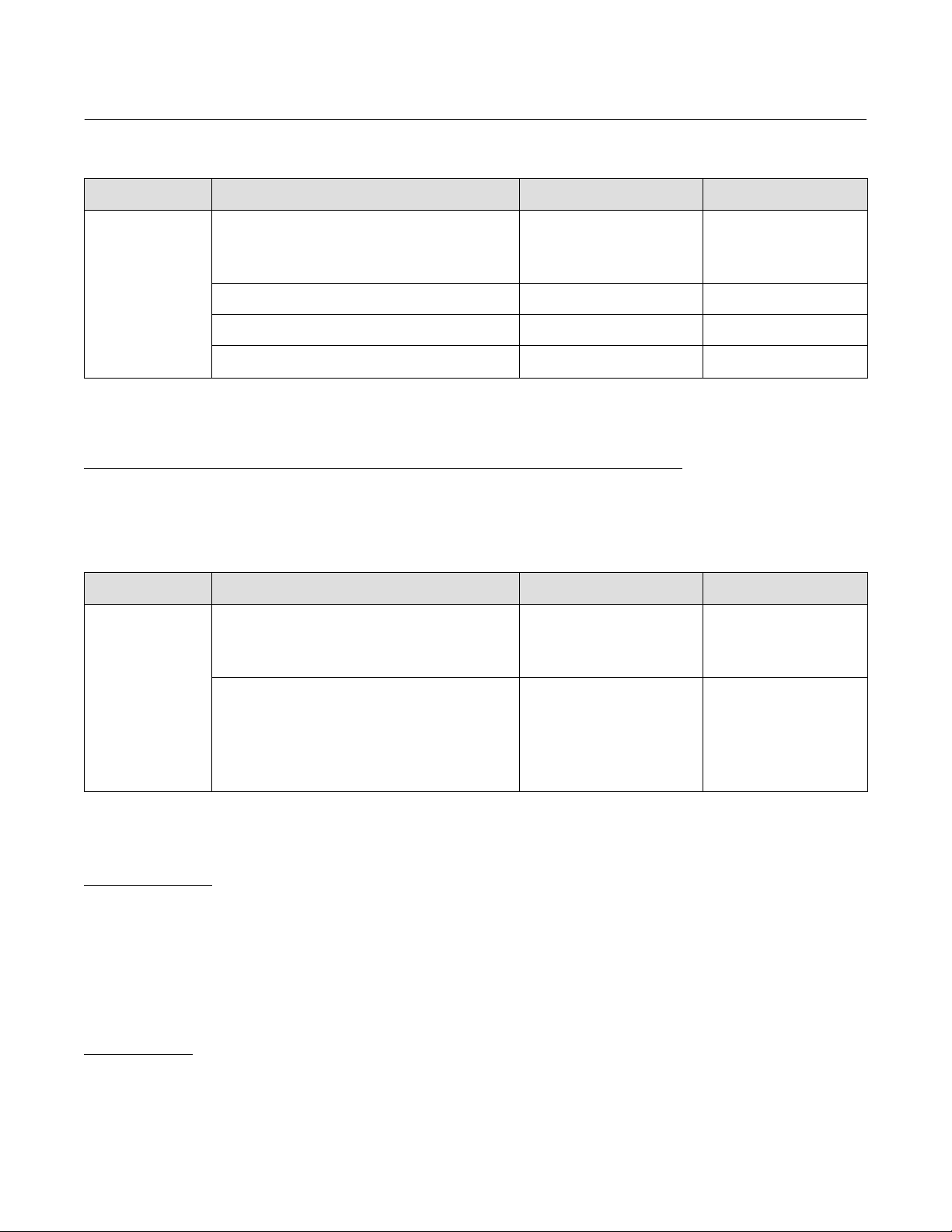
8. I valori predefiniti delle variabili di allarme verranno impostati come indicato di seguito:
Guida rapida
D103214X0IT
(campo tarato = valore massimo del campo di lavoro -
Variabile di allarme Valore predefinito dell'allarme
Allarme alto-alto Valore massimo del campo di lavoro
Allarme alto
Allarme basso
Allarme basso-basso Valore minimo del campo di lavoro
Strumento ad azione diretta
valore minimo del campo di lavoro)
95% del campo tarato + valore minimo del
campo di lavoro
5% del campo tarato + valore minimo del
campo di lavoro
(campo tarato = valore minimo del campo di lavoro -
Variabile di allarme Valore predefinito dell'allarme
Allarme alto-alto Valore minimo del campo di lavoro
Allarme alto
Allarme basso
Allarme basso-basso Valore massimo del campo di lavoro
Strumento ad azione inversa
valore massimo del campo di lavoro)
95% del campo tarato + valore massimo del
campo di lavoro
5% del campo tarato + valore massimo del
campo di lavoro
Le soglie di allarme PV sono inizializzate al 100%, 95%, 5% e 0% del campo tarato.
La banda morta dell'allarme PV è inizializzata allo 0,5% del campo tarato.
Gli allarmi PV sono tutti disabilitati. Gli allarmi di temperatura sono abilitati.
D Se era stata selezionata la modalità di densità, l'impostazione è stata completata.
D Se era stata selezionata la modalità di interfaccia o di densità, viene richiesto di immettere il peso specifico del fluido di
processo (in modalità di interfaccia dovranno essere immessi i valori del peso specifico dei fluidi di processo superiore e
inferiore).
Nota
Se per la taratura vengono usati pesi o acqua, immettere un peso specifico di 1,0 SGU. Per gli altri fluidi di prova, immettere il peso
specifico del fluido usato.
Per la compensazione della temperatura, accedere a Manual Setup (Impostazione manuale). In Process Fluid (Fluido di processo)
selezionare View Fluid Tables (Visualizza tabelle del fluido). La compensazione della temperatura viene abilitata immettendo valori
nelle tabelle del fluido.
Sullo strumento sono disponibili due tabelle del peso specifico che consentono di correggere il peso specifico in base alla
temperatura (fare riferimento alla sezione Impostazione manuale nel manuale di istruzioni). Per applicazioni di livello di interfaccia
vengono usate entrambe le tabelle. Per applicazioni di misura di livello viene usata solo la tabella del peso specifico inferiore. Per le
applicazioni di densità non viene usata alcuna tabella. Entrambe le tabelle possono essere modificate durante l'impostazione
manuale.
Nota
Potrebbe essere necessario modificare le tabelle esistenti per adattarle alle caratteristiche del fluido di processo in uso.
È possibile accettare la tabella o le tabelle attuali, modificare una singola voce o immettere manualmente una nuova tabella. Per
un'applicazione di interfaccia è possibile cambiare tra le tabelle del fluido superiore e inferiore.
22

Guida rapida
D103214X0IT
Controllore di livello digitale DLC3010
Luglio 2020
Taratura
Taratura guidata
Comunicatore da campo Configure > Calibration > Primary > Guided Calibration (2-5-1-1)
La funzione Guided Calibration (Taratura guidata) consiglia procedure di taratura appropriate per l'uso sul campo o al banco in base
ai dati immessi dall'utente. Per raggiungere la taratura consigliata, rispondere alle domande relative allo scenario di processo. Se
possibile, il metodo di taratura appropriato verrà avviato all'interno della procedura.
Esempi di taratura dettagliata
Taratura del sensore PV
Se si intende usare le funzionalità avanzate del trasmettitore, è necessario tarare il sensore PV.
Taratura - con dislocatore e tubo di torsione standard
Eseguire la taratura iniziale a una temperatura prossima a quella ambiente al campo tarato di progettazione per sfruttare appieno i
vantaggi della risoluzione disponibile. Per eseguire la taratura si utilizza un fluido di prova con peso specifico vicino a 1. Il valore del
peso specifico nella memoria dello strumento durante il processo di taratura deve corrispondere al valore del peso specifico del
fluido di prova usato per la taratura. Dopo la taratura iniziale lo strumento può essere impostato per un fluido target con un
determinato peso specifico, oppure per un'applicazione di interfaccia, per mezzo di semplici modifiche dei dati di configurazione.
1. Eseguire l'impostazione guidata e verificare che tutti i dati del sensore siano corretti.
Stabilire il livello del fluido di prova al punto di zero del processo desiderato. Controllare che il gruppo della leva del DLC3010 sia
accoppiato correttamente al tubo di torsione (fare riferimento alla procedura di accoppiamento a pagina 12). Per sbloccare il
gruppo della leva in modo che segua liberamente l'ingresso, chiudere il portello di accesso al giunto di accoppiamento sullo
strumento. Spesso è possibile osservare il visualizzatore dello strumento e/o l'uscita analogica per determinare quando il fluido
tocca il dislocatore, perché l'uscita non inizia a spostarsi verso l'alto finché tale punto non viene raggiunto.
Selezionare Min/Max calibration (Taratura min./max.) nel menu Full Calibration (Taratura completa) e confermare la richiesta di
essere alla condizione Min (Minima). Dopo avere accettato il punto Min, verrà richiesto di stabilire la condizione Max (Massima).
Affinché funzioni correttamente, la condizione displacer completely covered (Dislocatore completamente coperto) deve essere
leggermente al di sopra del contrassegno di livello 100%. Per esempio, 15 pollici sopra il contrassegno di zero sono generalmente
sufficienti per un dislocatore da 14 pollici su un sensore 249B, perché l'innalzamento previsto del dislocatore per questa
configurazione è di circa 0,6 pollici.
Accettare la condizione massima. Regolare il livello del fluido di prova e controllare il visualizzatore dello strumento e l'uscita di
corrente rispetto al livello esterno in differenti punti del campo tarato per verificare la taratura di livello.
Procedura:
Impostare la modalità PV su Level (Livello)
Se le osservazioni sui dati immessi vengono effettuate rispetto alla posizione della parte inferiore del dislocatore nelle
condizioni di processo più basse, impostare il valore dello scostamento di livello su 0.00
Impostare il peso specifico sul valore del peso specifico del fluido di prova utilizzato.
a. Per correggere errori di bias, eseguire la funzione Trim Zero (Taratura di zero) a una condizione di processo nota con certezza.
b. Per correggere errori di guadagno, eseguire la funzione Trim Gain (Regolazione del guadagno) a una condizione di alto livello
nota con certezza.
23

Controllore di livello digitale DLC3010
Luglio 2020
Nota
Se è possibile osservare in modo preciso i singoli stati di ingresso, è possibile utilizzare la taratura a due punti invece della
min./max.
Se non è possibile completare la taratura min./max. o quella a due punti, impostare la condizione di processo più bassa e Capture
Zero (Cattura di zero). Eseguire la funzione Trim Gain (Regolazione del guadagno) a un livello di processo almeno del 5% superiore
al campo tarato minimo.
Se l'uscita misurata non supera il valore di saturazione bassa finché il livello non è notevolmente al di sopra del fondo del
dislocatore, è possibile che il dislocatore sia sovradimensionato. Un dislocatore sovradimensionato rimane poggiato sul fermo
corsa inferiore finché non raggiunge una galleggiabilità sufficiente a far muovere la tiranteria. In tal caso, attenersi alla procedura di
taratura per dislocatori sovradimensionati descritta più avanti.
Dopo la taratura iniziale:
Per un'applicazione di livello - Accedere al menu Sensor Compensation (Compensazione del sensore) e usare Enter constant SG
(Immettere peso specifico costante) per configurare lo strumento per la densità del fluido di processo target.
Per un'applicazione di interfaccia - Cambiare la modalità PV a Interfaccia, verificare o regolare i valori del campo di lavoro presenti
nella procedura di modifica della modalità PV e quindi usare Enter constant SG (Immettere peso specifico costante) per configurare
lo strumento per il peso specifico di ciascuno dei fluidi di processo target.
Guida rapida
D103214X0IT
Per un'applicazione di densità - Cambiare la modalità PV a Densità e stabilire i valori del campo di lavoro desiderati nella procedura
Change PV mode (Modifica della modalità PV).
Se la temperatura target dell'applicazione è notevolmente inferiore o superiore a quella ambiente, consultare il manuale di
istruzioni del DLC3010 (D102748X012
Nota
Per informazioni su come calcolare in modo preciso la simulazione di questo effetto, consultare il supplemento al manuale di
istruzioni Simulazione delle condizioni di processo per la taratura dei controllori e dei trasmettitori di livello Fisher (D103066X012
disponibile tramite l'ufficio vendite Emerson
) per informazioni sulla compensazione della temperatura.
o sul sito www.Fisher.com.
Taratura con un dislocatore sovradimensionato
Quando i componenti del sensore sono dimensionati per un maggiore guadagno meccanico (come per alcune applicazioni di
misura di interfaccia o densità), il peso del dislocatore a secco è spesso superiore al carico ammissibile massimo del tubo di
torsione. In questa situazione è impossibile catturare la rotazione a galleggiabilità a zero del tubo di torsione, in quanto in questa
condizione la tiranteria è posata sul fermo corsa.
La procedura Capture Zero (Cattura di zero) nel gruppo di menu Partial Calibration (Taratura parziale) quindi non funziona
correttamente nelle modalità PV target di interfaccia o densità se il dislocatore è sovradimensionato.
Le procedure di taratura completa min./max., a due punti e in base al peso funzionano tutte correttamente alle condizioni di
processo effettive in modalità di interfaccia o densità, in quanto risalgono tramite calcoli all'angolo a galleggiabilità zero teorico
invece di catturarlo.
),
24

Guida rapida
D103214X0IT
Se è necessario usare i metodi di taratura parziale con un dislocatore sovradimensionato, è possibile usare la seguente
trasformazione:
Un'applicazione di interfaccia o densità può essere rappresentata matematicamente come un'applicazione di livello con un singolo
fluido la cui densità è uguale alla differenza tra i pesi specifici effettivi del fluido che copre il dislocatore ai due estremi di processo.
Il processo di taratura è il seguente:
D Impostare la modalità PV su Level (Livello).
D Impostare lo scostamento di livello su zero.
D Impostare i valori del campo di lavoro su:
LRV = 0.0,
URV = lunghezza del dislocatore
D Catturare lo zero alla condizione di processo più bassa (cioè dislocatore completamente immerso nel fluido con la densità
inferiore NON a secco).
D Impostare il peso specifico sulla differenza tra i pesi specifici dei due fluidi (per esempio, se SG_massimo = 0,87 e
SG_minimi = 1,0, per il peso specifico immettere il valore 0,13).
Controllore di livello digitale DLC3010
Luglio 2020
D Impostare una seconda condizione di processo che sia superiore alla condizione di processo minima di 5% del campo tarato
e utilizzare la procedura di regolazione del guadagno a tale condizione. Il guadagno sarà ora correttamente inizializzato.
(Lo strumento funzionerà correttamente in questa configurazione per un'applicazione di interfaccia. Tuttavia, per
un'applicazione di densità non sarà possibile riportare correttamente la PV in unità ingegneristiche se si conclude la taratura
dello strumento a questo punto).
Poiché il guadagno è valido:
D Impostare la modalità PV su Interfaccia o Densità.
D Riconfigurare il peso specifico del fluido o i valori del campo di lavoro sui valori o estremi effettivi del fluido.
D Usare la procedura di taratura di zero nel menu Partial Calibration (Taratura parziale) per risalire all'angolo teorico a
galleggiabilità zero tramite calcoli.
L'ultimo passaggio allinea il valore della PV in unità ingegneristiche all'osservazione indipendente.
Nota
Per informazioni su come simulare le condizioni di processo, consultare il supplemento al manuale di istruzioni Simulazione delle
condizioni di processo per la taratura dei controllori e dei trasmettitori di livello Fisher (D103066X012
vendite Emerson o sul sito www.Fisher.com.
), disponibile tramite l’ufficio
Di seguito sono riportate alcune linee guida sull'uso dei vari metodi di taratura del sensore nei casi quando per l'applicazione è
utilizzato un dislocatore sovradimensionato:
In base al peso: usare due pesi noti con precisione tra le condizioni di galleggiabilità minima e massima. Il peso totale del
dislocatore non è valido in quanto causerebbe l'arresto della tiranteria.
Min./max.: min. in questo caso significa che l'apparecchiatura è immersa nel fluido più leggero, mentre Max. indica l'immersione
nel fluido più pesante.
25

Controllore di livello digitale DLC3010
Luglio 2020
A due punti: usare due livelli di interfaccia che cadano effettivamente sul dislocatore. Più sono separati i livelli e migliore risulta il
livello di precisione. Se è possibile spostare il livello esattamente del 10%, il risultato dovrebbe essere preciso.
Teorico: se non è possibile modificare il livello, è possibile immettere manualmente un valore teorico per il valore nominale del
tubo di torsione, quindi eseguire la funzione Trim Zero (Taratura di zero) per regolare l'uscita all'osservazione indipendente attuale
della condizione di processo. Questo approccio può causare errori di guadagno e di bias, ma garantire una capacità di controllo
nominale. Per adeguare il valore della coppia nominale, tenere traccia delle osservazioni successive del processo attuale in rapporto
all'uscita dello strumento e alle diverse condizioni e utilizzare i rapporti tra le modifiche al processo e allo strumento. Ripetere la
funzione Zero Trim (Trim di zero) dopo ogni variazione del guadagno.
Guida rapida
D103214X0IT
Applicazioni di densità - con dislocatore e tubo di torsione standard
Nota
Quando si modifica PV is da livello o interfaccia a densità, i valori del campo di lavoro saranno inizializzati a 0,1 e 1,0 unità di peso
specifico. È possibile modificare i valori del campo e le unità di densità dopo l'inizializzazione. L'inizializzazione viene eseguita per
eliminare i valori numerici irrilevanti dalle dimensioni di lunghezza che non possono essere convertite in dimensioni di densità.
Nella modalità di densità è possibile utilizzare uno qualsiasi dei metodi di taratura completa del sensore (in base al peso, min./max.
e a due punti).
Min./max.: la taratura min./max. richiede per prima cosa il peso specifico del fluido di prova a densità minima (che può essere zero
se il dislocatore non è sovradimensionato). Quindi richiede di creare una condizione del dislocatore completamente sommerso con
il fluido. Successivamente, richiede il peso specifico del fluido di prova a densità massima e consente di sommergere
completamente il dislocatore nel fluido. Se l'operazione va a buon fine, la coppia nominale calcolata e l'angolo di riferimento zero
vengono visualizzati come riferimento.
A due punti: questo metodo richiede l'impostazione di due diverse condizioni di processo, le più diverse possibile. È possibile usare
due fluidi standard con densità nota e immergere alternatamente il dislocatore in uno o nell'altro. Se si intende simulare un fluido
usando una certa quantità d'acqua, è importante ricordare che è la porzione di dislocatore ricoperta d'acqua che conta, non la
quantità all'interno della gabbia. La quantità nella gabbia deve sempre essere leggermente superiore in considerazione del
movimento del dislocatore. Se l'operazione va a buon fine, la coppia nominale calcolata e l'angolo di riferimento zero vengono
visualizzati come riferimento.
In base al peso: questo metodo richiede la densità più bassa e quella più alta che si intendono usare per i punti di taratura e i valori
del peso vengono calcolati automaticamente. Se non è possibile indicare i valori esatti richiesti, tali valori possono essere modificati
in base ai pesi usati effettivamente. Se l'operazione va a buon fine, la coppia nominale calcolata e l'angolo di riferimento zero
vengono visualizzati come riferimento.
Taratura del sensore alle condizioni di processo (hot cut-over) quando l'ingresso non può
essere modificato
Se l'ingresso al sensore non può essere modificato per la taratura, è possibile configurare il guadagno dello strumento usando dati
teorici e la taratura di zero per tarare l'uscita in base alla condizione di processo corrente. Ciò consente di rendere operativo il
controllore e di controllare un livello prossimo al set point. Per perfezionare la stima del guadagno, è possibile confrontare le
variazioni di ingresso e di uscita nel corso del tempo. Dopo ciascuna regolazione del guadagno è necessario eseguire una nuova
taratura di zero. Questo approccio non è indicato per applicazioni di sicurezza, nelle quali conoscere con precisione il livello è
importante per prevenire condizioni di tracimazione o di serbatoio secco. Può tuttavia essere utilizzato per applicazioni di controllo
del livello nella norma, in grado di tollerare notevoli deviazioni da un set point del campo tarato medio.
La taratura a due punti consente di tarare il tubo di torsione usando due condizioni di ingresso che pongono il livello di interfaccia
calcolato in qualsiasi punto del dislocatore. La precisione di tale metodo aumenta proporzionalmente alla distanza tra i due punti,
ma il calcolo è possibile anche se il livello può essere spostato in alto o in basso anche solo del 5% del campo tarato. La maggior
parte dei processi di livello sono in grado di accettare piccole regolazioni manuali di tale tipo. Se il processo non è in grado di
accettare tali regolazioni, l'unico metodo possibile sarà l'approccio teorico.
26

Guida rapida
D103214X0IT
1. Stabilire tutte le informazioni possibili relative ai componenti hardware del sensore 249: tipo di sensore 249, orientamento di
montaggio (controllore a destra o a sinistra del dislocatore), materiale del tubo di torsione e spessore delle pareti, volume, peso
e lunghezza del dislocatore e lunghezza dell'asta di azionamento. La lunghezza dell'asta di azionamento non corrisponde alla
lunghezza dell'asta di sospensione, ma alla distanza orizzontale tra la linea media del dislocatore e la linea media del tubo di
torsione. Ottenere anche le informazioni relative al processo: densità dei fluidi, temperatura di processo e pressione. La
pressione viene usata come promemoria di prendere in considerazione la densità di una fase di vapore alta, la quale può
diventare significativa a pressioni più alte.
2. Eseguire l'impostazione dello strumento e immettere i vari dati richiesti nel modo più accurato possibile. Impostare i valori del
campo di lavoro (LRV, URV) sui valori della variabile di processo per ottenere rispettivamente uscite di 4 mA e 20 mA. Tali valori
possono essere 0 e 14 pollici su un dislocatore da 14 pollici.
3. Effettuare il montaggio e l'accoppiamento alle attuali condizioni di processo. Non eseguire la procedura Capture Zero (Cattura
di zero), perché non risulta accurata.
4. Tramite i dati relativi al tipo e al materiale del tubo di torsione, individuare un valore teorico per il valore nominale del tubo di
torsione effettivo o composto (fare riferimento al supplemento Simulazione delle condizioni di processo per la taratura dei
controllori e dei trasmettitori di livello Fisher per informazioni sui valori nominali teorici del tubo di torsione), quindi salvarlo
nella memoria dello strumento. È possibile accedere al valore selezionando:
Configure > Manual Setup > Sensor > Torque Tube > Change Torque Rate (2-2-1-3-2) (Configurazione > Impostazione manuale >
Sensore > Tubo di torsione > Modifica valore nominale (2-2-1-3-2)).
Selezionando l'opzione Need Assistance (Richiesta assistenza) invece dell'approccio Edit value directly (Modifica valore
direttamente), la procedura ricerca valori per i tubi di pressione normalmente disponibili.
5. Se la temperatura di processo è significativamente diversa dalla temperatura ambiente, fare uso di un fattore correttivo
interpolato dalle tabelle del modulo di rigidità normalizzato teorico. Prima di immettere i dati, moltiplicare il valore teorico per il
fattore correttivo per ottenere il guadagno corretto, con uno scarto approssimativo del 10%, almeno per i tubi di torsione corti
con pareti standard. Per tubi di torsione di lunghezza maggiore, come 249K, L, N, con pareti sottili ed estensione per isolatore
termico, i valori teorici sono molto meno precisi in quanto il percorso meccanico differisce in modo considerevole dalla teoria
lineare.
Controllore di livello digitale DLC3010
Luglio 2020
Nota
Tabelle con i dati sugli effetti della temperatura sui tubi di torsione sono incluse nel supplemento al manuale di istruzioni
Simulazione delle condizioni di processo per la taratura dei controllori e dei trasmettitori di livello Fisher (D103066X012
disponibile tramite l’ufficio vendite Emerson
al dispositivo collegati ad alcune applicazioni host con interfacce utente grafiche.
6. A questo punto ottenere una stima della condizione del processo corrente utilizzando un vetro spia o porte di campionatura.
Eseguire la procedura di taratura di zero e annotare il valore del processo effettivo in unità ingegneristiche della variabile di
processo.
7. A questo punto è possibile passare al controllo automatico. Se le osservazioni effettuate nel tempo indicano che l'uscita dello
strumento produce, per esempio, un'escursione pari a 1,2 volte il valore dell'ingresso indicato dal vetro spia, è possibile dividere
per 1,2 il valore nominale memorizzato del tubo di torsione e inviare il nuovo valore allo strumento. Eseguire quindi una nuova
taratura di zero e osservare i risultati per un lungo intervallo di tempo per stabilire se è necessaria un'ulteriore iterazione.
o sul sito www.Fisher.com. Questo documento è inoltre disponibile nei file della guida
),
27

Controllore di livello digitale DLC3010
Luglio 2020
Schemi
Guida rapida
D103214X0IT
Questa sezione include gli schemi di circuito necessari per cablare installazioni a sicurezza intrinseca. In caso di domande, rivolgersi
all'ufficio vendite Emerson
.
Figura 13. Schema di circuito CSA
SCHEMA DI INSTALLAZIONE PER ENTITÀ CSA
AREE PERICOLOSE
CLASSE I, GRUPPI A, B, C, D
CLASSE II, GRUPPI E, F, G
CLASSE III
DLC3010 FISHER
Vmax = 30 V c.c.
Imax = 226 mA
Ci = 5,5 nF
Li = 0,4 mH
VEDI NOTA 3
NOTE:
1. LE BARRIERE DEVONO ESSERE DOTATE DI CERTIFICAZIONE CSA
CON PARAMETRI DI ENTITÀ E DEVONO ESSERE INSTALLATE IN
CONFORMITÀ ALLE ISTRUZIONI DI INSTALLAZIONE A
SICUREZZA INTRINSECA DEL PRODUTTORE.
2. L'APPARECCHIATURA DEVE ESSERE INSTALLATA IN
CONFORMITÀ AL CODICE ELETTRICO CANADESE, PARTE 1.
3. SE SI USA UN COMUNICATORE PORTATILE O IL MULTIPLEXER,
DEVE ESSERE DOTATO DI CERTIFICAZIONE CSA E INSTALLATO IN
CONFORMITÀ AL DISEGNO DI CONTROLLO DEL PRODUTTORE.
4. PER L'INSTALLAZIONE DI ENTITÀ: Vmax > Voc, Imax > Isc
Ci + Ccable < Ca, Li + Lcable < La
28B5744-B
AREE NON PERICOLOSE
BARRIERA CON
CERTIFICAZIONE CSA
28

Guida rapida
D103214X0IT
Figura 14. Schema di circuito FM
A SICUREZZA INTRINSECA CLASSE I, II, III, DIV. 1,
A PROVA DI ACCENSIONE CLASSE I, DIV. 2,
AREE PERICOLOSE
GRUPPI A, B, C, D, E, F, G
GRUPPI A, B, C, D
Controllore di livello digitale DLC3010
Luglio 2020
AREE NON PERICOLOSE
DLC3010 FISHER
Vmax = 30 V c.c.
Imax = 226 mA
Ci = 5,5 nF
Li = 0,4 mH
Pi = 1,4 W
1. L'INSTALLAZIONE DEVE ESSERE CONFORME AL CODICE ELETTRICO
NAZIONALE (NEC), NFPA 70, ARTICOLO 504 E ANSI/ISA RP12.6.
2. LE APPLICAZIONI DI CLASSE 1, DIV. 2 DEVONO ESSERE INSTALLATE
COME SPECIFICATO NELL'ARTICOLO NEC 501-4(B).
L'APPARECCHIATURA E IL CABLAGGIO SUL CAMPO SONO A PROVA DI
ACCENSIONE SE COLLEGATI A BARRIERE APPROVATE CON
PARAMETRI DI ENTITÀ.
3. I CIRCUITI DEVONO ESSERE COLLEGATI IN CONFORMITÀ ALLE
ISTRUZIONI DEL PRODUTTORE DELLA BARRIERA.
4. LA TENSIONE MASSIMA IN AREE SICURE NON DEVE SUPERARE 250 Vrms.
5. LA RESISTENZA TRA LA MASSA DELLA BARRIERA E LA MESSA A TERRA
DEVE ESSERE INFERIORE A 1 .
6. CONDIZIONI DI FUNZIONAMENTO NORMALI 30 V c.c. 20 mA c.c.
7. SE SI USA IL COMUNICATORE PORTATILE O IL MULTIPLEXER, DEVE
ESSERE DOTATO DI CERTIFICAZIONE FM E INSTALLATO IN
CONFORMITÀ AL DISEGNO DI CONTROLLO DEL PRODUTTORE.
8. PER L'INSTALLAZIONE DI ENTITÀ (A SICUREZZA INTRINSECA E A
PROVA DI ACCENSIONE);
Vmax > Voc o Vt Ci + Ccable < Ca
Imax > Isc o It Li + Lcable < La
Pi > Po o Pt
9. LA CUSTODIA DELL'APPARECCHIO CONTIENE ALLUMINIO E
COSTITUISCE UN POTENZIALE RISCHIO DI IGNIZIONE CAUSATA DA
URTI O ATTRITO. PER PREVENIRE IL RISCHIO DI IGNIZIONE, EVITARE
GLI URTI E L'ATTRITO DURANTE L'INSTALLAZIONE E IL FUNZIONAMENTO.
28B5745-C
VEDI NOTA 7
BARRIERA CON
CERTIFICAZIONE FM
Specifiche
Le specifiche dei controllori di livello digitali DLC3010 sono riportate nella Tabella 6, quelle dei sensori 249 nella Tabella 8.
29

Controllore di livello digitale DLC3010
Luglio 2020
Tabella 6. Specifiche del controllore di livello digitale DLC3010
Guida rapida
D103214X0IT
Possibili configurazioni
Montaggio su sensori 249 con gabbia e senza gabbia. Fare
riferimento alle Tabelle 11 e 12 e alla descrizione dei
sensori.
Funzione: trasmettitore
Protocollo di comunicazione: HART
Segnale di ingresso
Livello, interfaccia o densità: moto rotatorio della barra di
torsione proporzionale alle variazioni del livello del fluido,
del livello di interfaccia o della densità che modificano la
galleggiabilità di un dislocatore.
Temperatura di processo: interfaccia per termoresistenze
RTD di platino da 100 Ω a 2 o a 3 fili per il rilevamento della
temperatura di processo o temperatura target immessa
dall'utente (opzionale) per consentire la compensazione di
eventuali variazioni del peso specifico.
Segnale di uscita
Analogico: da 4 a 20 mA c.c. (J azione diretta: all'aumento
del livello, dell'interfaccia o della densità corrisponde un
aumento dell'uscita, oppure J azione inversa: all'aumento
del livello, dell'interfaccia o della densità corrisponde una
diminuzione dell'uscita).
Saturazione alta: 20,5 mA
Saturazione bassa: 3,8 mA
Allarme alto: 22,5 mA
Allarme basso: 3,7 mA
Per ciascuna configurazione è disponibile solo una delle
definizioni di allarme alto/basso riportate sopra. Conforme
a NAMUR NE 43 quando è selezionata l'opzione di livello di
allarme alto.
Digitale: HART 1200 baud FSK (spostamento di frequenza)
Per abilitare le comunicazioni è necessaria la conformità ai
requisiti di impedenza HART. L'impedenza della derivazione
totale attraverso le connessioni dell'apparecchiatura
principale (esclusa l'impedenza del trasmettitore e del
dispositivo principale) deve essere compresa tra 230 e
600 Ω. L'impedenza di ricezione HART del trasmettitore è
definita come:
Rx: 42 kΩ e
Cx: 14 nF
Si noti che nella configurazione punto a punto sono
disponibili sia la segnalazione digitale che analogica. È
possibile richiedere dati allo strumento in modalità digitale,
oppure è possibile impostare lo strumento in modalità
burst per trasmettere digitalmente dati di processo non
sollecitati. In modo multidrop la corrente di uscita è fissa a
4 mA ed è disponibile solo la comunicazione digitale.
Prestazioni
(1)
Con 249W da
3 pollici e
dislocatore da
14 pollici
$0,8% del
campo tarato
di uscita
- - - - - -
$0,5% del
campo tarato
di uscita
- - - - - -
<1,0% del
campo tarato
di uscita
Con tutti
gli altri
sensori 249
$0,5% del
campo tarato
di uscita
$0,3% del
campo tarato
di uscita
<1,0% del
campo tarato
di uscita
Criteri di
prestazione
Linearità
indipendente
Isteresi
Ripetibilità
Banda morta
Isteresi + Banda
morta
NOTA: al campo tarato di progettazione, condizioni di riferimento.
1. Agli ingressi di rotazione del gruppo della leva.
Controllore di
livello digitale
DLC3010
$0,25% del
campo tarato
di uscita
<0,2% del
campo tarato
di uscita
$0,1%
dell'uscita
fondo scala
<0,05% del
campo tarato
di ingresso
- - -
A una banda proporzionale (PB) effettiva <100%, linearità,
banda morta, ripetibilità, effetto dell'alimentazione e
influenza della temperatura ambiente sono
potenzialmente declassati dal fattore (100%/PB).
Influenze operative
Effetto dell'alimentazione: l'uscita varia < ± 0,2% del fondo
scala quando l'alimentazione varia tra le specifiche di
tensione minima e massima.
Protezione per sovratensioni: i terminali del circuito sono
protetti da un soppressore di sovratensioni. Le specifiche
sono le seguenti:
Forma d'onda a impulsi
Tempo di
salita s)
10 1000 93,6 16
Nota: μs = microsecondi
Decadimento
al 50% s)
8 20 121 83
V
(tensione di
CL
clamping) max.
(V)
I
(picco
PP
d'impulso alla
corrente) max. (A)
Temperatura ambiente: l'effetto combinato della
temperatura sullo zero e sul campo tarato senza il
sensore 249 è inferiore allo 0,03% del fondo scala per
grado Kelvin per un campo operativo da -40 a 80 _C
(da -40 a 176 _F).
Temperatura di processo: la coppia nominale subisce
l'effetto della temperatura di processo. Anche la densità di
processo può essere influenzata dalla temperatura di
processo.
Densità di processo: la sensibilità all'errore nel calcolo della
densità di processo è proporzionale alla densità
differenziale della taratura. Se il peso specifico differenziale
è pari a 0,2, un errore di 0,02 unità di peso specifico nel
calcolo della densità di un fluido di processo rappresenta il
10% del campo tarato.
30
-continua-

Guida rapida
D103214X0IT
Tabella 6. Specifiche del controllore di livello digitale DLC3010 (continua)
Controllore di livello digitale DLC3010
Luglio 2020
Compatibilità elettromagnetica
Conforme a EN 61326‐1:2013 e EN 61326‐2‐3:2006
Immunità - Ambienti industriali in conformità alla
Tabella 2 della norma EN 61326-1 e alla Tabella AA.2
della norma EN 61326-2-3. Le prestazioni sono
riportate nella Tabella 7 che segue.
Emissioni - Classe A
Classificazione ISM dell'apparecchiatura: Gruppo 1,
Classe A
Requisiti di alimentazione (Figura 10)
Da 12 a 30 V c.c.
; 22,5 mA
Lo strumento è dotato di protezione contro l'inversione
della polarità.
Per garantire la comunicazione HART è richiesta una
tensione disponibile massima di 17,75.
Compensazione
Compensazione del trasduttore: per la temperatura
ambiente
Compensazione del parametro di densità: per la
temperatura di processo (sono necessarie tabelle fornite
dall'utente)
Compensazione manuale: è possibile per il valore nominale
del tubo di torsione alla temperatura di processo target
Dispositivi di controllo digitali
Collegati al segnale di allarme analogico Hi (Alto,
impostazione di fabbrica) o Lo (Basso) selezionabile tramite
cavallotto:
Trasduttore di posizione del tubo di torsione: dispositivo di
controllo dell'azionamento e dispositivo di controllo della
validità del segnale
Allarmi configurabili dall'utente: allarmi di processo limite
Hi-Hi e Lo-Lo
Solo leggibile tramite HART:
Dispositivo di controllo della validità del segnale della
termoresistenza RTD: quando è installata la termoresistenza
RTD
Dispositivo di controllo del tempo libero del processore.
Dispositivo di controllo della scrittura nella memoria non
volatile.
Allarmi configurabili dall'utente: allarmi di processo limite Hi
e Lo, allarmi di temperatura di processo limite Hi e Lo e
allarmi di temperatura dell'elettronica limite Hi e Lo
Diagnostica
Diagnostica della corrente del circuito di uscita.
Diagnostica dell'indicatore LCD.
Misura puntuale del peso specifico in modalità di livello: usata
per aggiornare il parametro del peso specifico per
migliorare la misura di processo
Capacità di tracciatura del segnale digitale: tramite revisione
delle variabili di risoluzione dei problemi e
capacità di generazione di andamenti per PV, TV ed SV.
Indicazioni dell'indicatore LCD
L'indicatore LCD indica l'uscita analogica su un diagramma
a barre in scala percentuale. L'indicatore può inoltre essere
configurato per visualizzare:
Solo la variabile di processo in unità ingegneristiche.
Solo il campo percentuale.
Il campo percentuale alternato alla variabile di processo
oppure La variabile di processo alternata alla temperatura di
processo (e ai gradi di rotazione dell'albero pilota).
Classificazione elettrica
Inquinamento Grado IV, Sovratensione Categoria II
secondo la norma IEC 61010 clausola 5.4.2 d
Aree pericolose:
CSA - A sicurezza intrinseca, a prova di esplosione,
Divisione 2, a prova di accensione per polveri
FM - A sicurezza intrinseca, a prova di esplosione, a prova
di accensione, a prova di accensione per polveri
ATEX - A sicurezza intrinseca, tipo n, a prova di fiamma
IECEx - A sicurezza intrinseca, tipo n, a prova di fiamma
Per ulteriori informazioni, fare riferimento alle certificazioni
per aree pericolose e alle istruzioni speciali per l'uso sicuro e
per l'installazione in aree pericolose nella sezione
Installazione, a partire da pagina 5.
Custodia dell'elettronica:
CSA - Tipo 4X
FM - NEMA 4X
ATEX - IP66
IECEx - IP66
Altre certificazioni
CML - Certification Management Limited (Giappone)
CUTR - Customs Union Technical Regulations (Russia,
Kazakhstan, Belarus e Armenia)
INMETRO - National Institute of Metrology,
Standardization, and Industrial Quality (Brasile)
KTL - Korea Testing Laboratory (Corea del Sud)
NEPSI - National Supervision and Inspection Centre for
Explosion Protection and Safety of Instrumentation (Cina)
PESO CCOE - Petroleum and Explosives Safety Organisation
- Chief Controller of Explosives (India)
Per informazioni dettagliate su specifiche certificazioni,
rivolgersi all'ufficio vendite Emerson
-continua-
31

Controllore di livello digitale DLC3010
Luglio 2020
Tabella 6. Specifiche del controllore di livello digitale DLC3010 (continua)
Guida rapida
D103214X0IT
Peso specifico differenziale minimo
Con una rotazione nominale della barra di torsione di
4,4 gradi per una variazione da 0% a 100% del livello del
fluido (peso specifico = 1), il controllore di livello digitale
può essere regolato per fornire un'uscita completa per un
Connessioni elettriche
Due connessioni del conduit interne da 1/2-14 NPT, una sul
fondo e una sul retro della morsettiera. Sono disponibili
adattatori M20.
campo di ingresso del 5% del campo tarato di ingresso
nominale. Ciò corrisponde a un peso specifico differenziale
Opzioni
minimo di 0,05 con dislocatori di volume standard.
Fare riferimento alle specifiche del sensore 249 per i volumi
del dislocatore standard e per i tubi di torsione a parete
standard. Il volume standard dei modelli 249C e 249CP è
∼980 cm
un volume standard di ∼1640 cm
3
(60 in.3); la maggior parte degli altri modelli ha
3
(100 in.3).
Il funzionamento a una banda proporzionale del 5%
compromette la precisione di un fattore di 20. Se si usa un
tubo di torsione a pareti sottili o si raddoppia il volume del
dislocatore, si raddoppia approssimativamente la banda
proporzionale effettiva. Quando la banda proporzionale del
J Isolatore termico J Sono disponibili supporti per
dislocatori Masoneilant, Yamatake e Foxborot/Eckhardt
J È disponibile il test di serie della segnatura di livello
(rapporto di convalida delle prestazioni) (solo EMA) per
strumenti montati in fabbrica su sensori 249 J Taratura di
fabbrica: disponibile per strumenti montati in fabbrica su
sensori 249, quando vengono indicate applicazione,
temperatura e densità di processo J L'apparecchiatura è
compatibile con un indicatore remoto specificato
dall'utente.
sistema scende al di sotto del 50%, si dovrebbe considerare
di cambiare dislocatore o tubo di torsione se uno dei
Limiti operativi
requisiti dell'applicazione è l'alta precisione.
Posizioni di montaggio
I controllori di livello digitali possono essere montati a
Temperatura di processo: fare riferimento alla Tabella 9 e
alla Figura 8
Temperatura ambiente e umidità: vedere di seguito
destra o a sinistra del dislocatore (Figura 5).
Con l'orientamento dello strumento normale, lo sportello
di accesso al giunto di accoppiamento è posizionato sul
Condizioni
fondo, per fornire uno scarico adeguato della camera della
leva e della morsettiera e per limitare l'effetto
gravitazionale sul gruppo della leva. Se l'utente fornisce
uno scarico alternativo e un piccolo calo delle prestazioni è
accettabile, lo strumento può essere montato a incrementi
di 90 gradi attorno all'asse dell'albero pilota. Per facilitare
Temperatura
ambiente
Umidità
relativa
ambiente
tale procedura, l'indicatore LCD può essere ruotato a
incrementi di 90 gradi.
Materiali di costruzione
Custodia e coperchio: lega di alluminio a basso tenore
Valore altitudine
Fino a 2000 metri (6562 feet)
di rame
Interno: acciaio placcato, alluminio e acciaio inossidabile;
Peso
schede a circuito stampato incapsulate; magneti al
neodimio-ferro-boro
NOTA: i termini specialistici relativi agli strumenti sono definiti nella norma ANSI/ISA 51.1 - Terminologia per strumenti di processo.
1. A temperature inferiori a -20 _C (-4 _F) l'indicatore LCD potrebbe essere illeggibile.
2. Se sono richieste temperature di esercizio superiori a questi limiti, rivolgersi all’ufficio vendite Emerson
Inferiore a 2,7 kg (6 lb)
o all’ingegnere responsabile dell’applicazione.
Limiti
(1,2)
normali
da -40 a 80 _C
(da -40 a 176 _F)
Da 0 a 95%,
(non
condensante)
Limiti di
trasporto e
conservazione
da -40 a 85 _C
(da -40 a 185 _F)
Da 0 a 95%,
(non
condensante)
Riferimento
nominale
25 _C
(77 _F)
40%
32

Guida rapida
(1)
D103214X0IT
Controllore di livello digitale DLC3010
Tabella 7. Riepilogo dei risultati di compatibilità elettromagnetica - Immunità
Bocca Fenomeno Norma base Livello di prova
Scarica elettrostatica (ESD) IEC 61000-4-2
Campo di radiazioni
Custodia
Segnale/comando di
ingresso/uscita
Nota: la lunghezza del cablaggio della termoresistenza RTD deve essere inferiore a 3 m (9.8 ft).
1. A = Nessuna degradazione durante le prove. B = Degradazione temporanea durante le prove, a recupero automatico. Limite di specifica = +/-1% del campo tarato.
2. La comunicazione HART è stata considerata non rilevante per il processo ed è usata principalmente per la configurazione, la taratura e la diagnostica.
elettromagnetiche
Campo magnetico di
frequenza alla corrente
nominale
Burst IEC 61000-4-4 1 kV A
Sovracorrente momentanea IEC 61000-4-5 1 kV (solo da linea a terra, ciascuno) B
Radiofrequenza condotta IEC 61000-4-6 Da 150 kHz a 80 MHz a 3 Vrms A
IEC 61000-4-3
IEC 61000-4-8 60 A/m a 50 Hz A
4 kV contatto
8 kV aria
Da 80 a 1000 MHz a 10 V/m con 1 kHz AM all'80%
Da 1400 a 2000 MHz a 3V/m con 1 kHz AM all'80%
Da 2000 a 2700 MHz a 1V/m con 1 kHz AM all'80%
Tabella 8. Specifiche del sensore 249
Segnale di ingresso
Livello del liquido o livello di interfaccia tra liquido e liquido:
da 0 a 100% della lunghezza del dislocatore
Densità del liquido: variazione da 0 a 100% della forza di
spostamento ottenuta con un dato volume del dislocatore i volumi standard sono J 980 cm
249C e 249CP o J 1640 cm
3
(60 in.3) per sensori
3
(100 in.3) per la maggior
parte degli altri sensori; sono disponibili altri volumi a
seconda della configurazione del sensore
Lunghezze del dislocatore del sensore
Fare riferimento alle note delle Tabelle 11 e 12
Pressioni di esercizio del sensore
Conformi ai requisiti di temperatura/pressione ANSI
applicabili per le specifiche configurazioni del sensore
riportate nelle Tabelle 11 e 12
Tipi di connessione del sensore con gabbia
Le gabbie sono disponibili con diversi tipi di connessione
per facilitare il montaggio su serbatoio; i tipi di connessioni
equilibratrici sono numerati e sono illustrati nella Figura 15.
Posizioni di montaggio
La maggior parte dei sensori di livello a dislocatore con
gabbia sono dotati di una testa rotante. La testa può
ruotare di 360 gradi in otto posizioni diverse (Figura 5).
Materiali di costruzione
Fare riferimento alle Tabelle 10, 11 e 12
Temperatura ambiente di esercizio
Fare riferimento alla Tabella 9
Per i campi di temperatura ambiente, le linee guida e l'uso
di un isolatore termico opzionale, fare riferimento alla
Figura 8.
Opzioni
J Isolatore termico J Vetro spia per pressioni fino a 29 bar
a 232 _C (420 psig a 450 _F) e J Riflettometri per
applicazioni a pressioni e temperature elevate
Luglio 2020
Criteri di
prestazione
A
A
(1)(2)
Tabella 9. Temperature di processo consentite
per materiali di limite di pressione comuni del
sensore 249
MATERIALE
Ghisa -29 _C (-20 _F) 232 _C (450 _F)
Acciaio -29 _C (-20 _F) 427 _C (800 _F)
Acciaio inossidabile -198 _C (-325 _F) 427 _C (800 _F)
N04400 -198 _C (-325 _F) 427 _C (800 _F)
Guarnizioni in laminato di
grafite/acciaio inossidabile
Guarnizioni in N04400/PTFE -73 _C (-100 _F) 204 _C (400 _F)
TEMPERATURA DI PROCESSO
Min. Max.
-198 _C (-325 _F) 427 _C (800 _F)
Tabella 10. Materiali del dislocatore e del tubo di
torsione
Componente
Dislocatore
Stelo del dislocatore,
cuscinetto pilota,
asta e azionatore del
dislocatore
Tubo di torsione N05500
1. N05500 non è indicato per applicazioni in cui la molla sia sottoposta
a temperature superiori a 232 _C (450 _F). Se sono richieste
temperature di esercizio superiori a questo limite, rivolgersi all’ufficio
vendite Emerson o all’ingegnere responsabile dell’applicazione.
Materiale
standard
Acciaio
inossidabile 304
Acciaio
inossidabile 316
Altri materiali
Acciaio inossidabile 316,
N10276, N04400,
plastica e leghe speciali
N10276, N04400, altri
acciai inossidabili
austenitici e leghe
speciali
Acciaio inossidabile 316,
N06600, N10276
33

Controllore di livello digitale DLC3010
(1)
(5)
(1)
(3)
Luglio 2020
Guida rapida
D103214X0IT
Tabella 11. Sensori a dislocatore con gabbia
ORIENTAMENTO
DEL TUBO DI
TORSIONE
SENSORE
(3)
249
MATERIALE STANDARD
DELLA GABBIA, DELLA
TESTA E DEL TUBO DI
TORSIONE
Ghisa
A vite
Flangiato 2
A vite o a tasca a saldare opzionale
249B, 249BF
Braccio del
tubo di torsione
(4)
Acciaio
A faccia piana (RF) o a flangia RTJ
opzionale
rotante rispetto
alle connessioni
A vite
equilibratrici
(3)
249C
Acciaio inossidabile 316
Flangia RF
249K Acciaio
A faccia piana (RF) o a flangia RTJ
opzionale
249L Acciaio Flangia RTJ 2
1. Le lunghezze del dislocatore standard per tutti gli stili (tranne 249) sono 14, 32, 48, 60, 72, 84, 96, 108 e 120 pollici. Per il 249 è richiesto un dislocatore con lunghezza di 14 o 32 pollici.
2. Connessioni a flangia EN sono disponibili nella regione EMA (Europa, Medio Oriente e Africa).
3. Non disponibile nella regione EMA.
4. Il 249BF è disponibile solo in EMA. Disponibile anche nella dimensione EN DN 40 con flange da PN 10 a PN 100 e nella dimensione DN 50 con flange da PN 10 a PN 63.
5. La connessione in alto è a flangia RTJ da 1 pollice per tipi di connessione F1 e F2.
CONNESSIONE EQUILIBRATRICE
Stile
Dimensione
(pollici)
1-1/2
oppure 2
1-1/2
oppure 2
1-1/2
2
1-1/2
oppure 2
1-1/2
2
1-1/2
oppure 2
PRESSIONE
NOMINALE
CL125 oppure
CL250
CL600
CL150, CL300 o
CL600
CL150, CL300 o
CL600
CL600
CL150, CL300 o
CL600
CL150, CL300 o
CL600
CL900 o CL1500
CL2500
(2)
Tabella 12. Sensori a dislocatore senza gabbia
Materiale standard della
(2)
testa
Montaggio Sensore
249BP
Montaggio sulla
249CP Acciaio inossidabile 316 A faccia piana (RF) da 3 pollici CL150, CL300 o CL600
(4)
wafer
Acciaio
sommità del
serbatoio
249P
(5)
Acciaio o acciaio
inossidabile
WCC (acciaio), LCC
Montaggio sul
lato del serbatoio
249VS
(acciaio) o CF8M (acciaio
inossidabile 316)
WCC, LCC o CF8M Per estremità saldata di testa da 4 pollici, XXS CL2500
Montaggio sulla
sommità del
serbatoio o su
249W
gabbia fornita dal
cliente
1. Le lunghezze del dislocatore standard sono 14, 32, 48, 60, 72, 84, 96, 108 e 120 pollici.
2. Non utilizzato per sensori a montaggio laterale.
3. Connessioni a flangia EN disponibili nella regione EMA (Europa, Medio Oriente e Africa).
4. Non disponibile nella regione EMA.
5. Il 249P è disponibile solo nella regione EMA.
6. Il corpo wafer è applicabile solo al 249W.
WCC o CF8M Per RF da 3 pollici CL150, CL300 o CL600
LCC o CF8M Per RF da 4 pollici CL150, CL300 o CL600
, del corpo
(6)
e del braccio del
tubo di torsione
Connessione flangiata (dimensione) Pressione nominale
A faccia piana (RF) o RTJ opzionale da 4 pollici CL150, CL300 o CL600
A faccia piana (RF) da 6 o 8 pollici CL150 o CL300
A faccia piana (RF) o RTJ opzionale da 4 pollici
A faccia piana (RF) da 6 o 8 pollici
CL900 o CL1500
(EN PN 10 - DIN PN 250)
CL150, CL300, CL600, CL900,
CL1500 o CL2500
CL125, CL150, CL250, CL300,
Per RF o FF da 4 pollici
CL600, CL900 o CL1500
(EN PN 10 - DIN PN 160)
34

Guida rapida
D103214X0IT
Figura 15. Diversi stili di connessione equilibratrice
Controllore di livello digitale DLC3010
Luglio 2020
CONNESSIONI SUPERIORE E
STILE 1
INFERIORE, A VITE (S-1) O
FLANGIATE (F-1)
Simboli degli strumenti
Simbolo Descrizione Posizione sullo strumento
CONNESSIONI LATERALI SUPERIORE E
INFERIORE, A VITE (S-3) O FLANGIATE (F-3)
STILE 2
CONNESSIONI SUPERIORE E LATERALE
INFERIORE, A VITE (S-2) O FLANGIATE
(F-2)
Bloccaggio della leva Impugnatura
Sbloccaggio della leva Impugnatura
Messa a terra Custodia della morsettiera
STILE 3
STILE 4
CONNESSIONI LATERALE SUPERIORE E
INFERIORE, A VITE (S-4) O FLANGIATE
(F-4)
NPT Custodia della morsettiera
T Test All'interno della morsettiera
+ Positivo All'interno della morsettiera
_ Negativo All'interno della morsettiera
RS Connessione RTD All'interno della morsettiera
R1 Connessione RTD 1 All'interno della morsettiera
R2 Connessione RTD 2 All'interno della morsettiera
35

Controllore di livello digitale DLC3010
Luglio 2020
Guida rapida
D103214X0IT
Emerson, Emerson Automation Solutions e tutte le loro affiliate non si assumono alcuna responsabilità per la selezione, l'uso o la manutenzione dei propri
prodotti. La responsabilità per la selezione, l'uso e la manutenzione corretti dei prodotti è esclusivamente dell'acquirente e dell'utente finale.
Fisher e FIELDVUE sono marchi di proprietà di una delle aziende della divisione commerciale Emerson Automation Solutions di Emerson Electric Co.
Emerson Automation Solutions, Emerson e il logo Emerson sono marchi di fabbrica e marchi di servizio di Emerson Electric Co. HART è un marchio di fabbrica
registrato di FieldComm Group. Tutti gli altri marchi appartengono ai rispettivi proprietari.
I contenuti di questa pubblicazione sono presentati solo a scopo informativo e, anche se è stato fatto il possibile per garantirne l'accuratezza, tali contenuti non
devono essere interpretati come garanzie, espresse o implicite, in relazione ai prodotti e ai servizi qui descritti, al loro uso o alla loro applicabilità. Tutte le vendite
sono soggette ai nostri termini e condizioni, che sono disponibili su richiesta. Ci riserviamo il diritto di apportare modifiche o migliorie al design o alle specifiche
di tali prodotti in qualsiasi momento e senza obbligo di preavviso.
Emerson Automation Solutions
Marshalltown, Iowa 50158 USA
Sorocaba, 18087 Brazil
Cernay, 68700 France
Dubai, United Arab Emirates
Singapore 128461 Singapore
www.Fisher.com
36
E 2005, 2020 Fisher Controls International LLC. Tutti i diritti riservati.
 Loading...