


Instruction Manual
D102030X012
Fisherr SS-83 Angle Valve
Contents
Introduction 1.................................
Scope of Manual 1.............................
Description 1.................................
Specifications 1...............................
Installation 2..................................
Maintenance 3.................................
Introduction
SS-83 Valve
March 2013
Packing Lubrication 4..........................
Packing Maintenance 5.........................
Replacing Packing 7........................
Trim Maintenance 9...........................
Parts Ordering 10...............................
Parts List 11...................................
Scope of Manual
This instruction manual includes installation, maintenance, and parts information for the Fisher SS-83 angle valve
(figure 1). Refer to separate manuals for instructions covering the actuator and accessories.
Do not install, operate, or maintain an SS-83 valve without being fully trained and qualified in valve, actuator, and
accessory installation, operation, and maintenance. To avoid personal injury or property damage, it is important to
carefully read, understand, and follow all the contents of this manual, including all safety cautions and warnings. If you
have any questions about these instructions, contact your Emerson Process Management sales office before
proceeding.
Description
The SS-83 is an integral bonnet angle control valve. It is designed for handling highly corrosive fluids and is usually
mounted on a tank. Body sizes refer to nominal inlet and outlet dimensions (for example, a 4 x 6 body has an NPS 4
nominal inlet and an NPS 6 nominal outlet).
Specifications
Some specifications for this valve can be found on the valve or actuator nameplate. Other specifications and limits
were specified when you ordered this valve. If you are not sure what the specifications and limits for this valve are,
contact your Emerson Process Management sales office. Specify the valve serial number and any other information
about the valve.
www.Fisher.com

SS-83 Valve
March 2013
Instruction Manual
D102030X012
Installation
WARNING
Always wear protective gloves, clothing, and eyewear when performing any installation operations to avoid personal
injury.
Personal injury or equipment damage caused by sudden release of pressure may result if the valve assembly is installed
where service conditions could exceed the limits specified when the valve was purchased or on the appropriate
nameplates. To avoid such injury or damage, provide a relief valve for over-pressure protection as required by government
or accepted industry codes and good engineering practices.
Check with your process or safety engineer for any additional measures that must be taken to protect against process
media.
If installing into an existing application, also refer to the WARNING at the beginning of the Maintenance section in this
instruction manual.
CAUTION
When ordered, the valve configuration and construction materials were selected to meet particular pressure, temperature,
pressure drop and controlled fluid conditions. Because some body/trim material combinations are limited in their pressure
drop and temperature ranges, do not apply any other conditions to the valve without first contacting your Emerson
Process Management sales office.
If hoisting the valve, use a nylon sling to protect the surfaces. Carefully position the sling to prevent damage to the actuator
tubing and any accessories. Also, take care to prevent people from being injured in case the hoist or rigging slips
unexpectedly. Be sure to use adequately sized hoists and chains or slings to handle the valve.
1. Before installing the valve, inspect the valve body cavity and associated equipment for any damage and any foreign
material.
2. Make certain the body interior is clean, that pipelines are free of foreign material, and that the valve is oriented so
that pipeline flow is in the same direction as the arrow on the side of the valve.
3. If possible, install the valve with the valve stem vertical. All valves with size 80 or larger actuators mounted between
45_ above and 45_ below horizontal should be supported. Small actuators might also need support if vibrational or
other non-gravitational forces are present. For more information on seismic considerations, consult your Emerson
Process Management sales office.
4. Use accepted piping, flange, or welding practices when installing the valve in the line. For flanged valve bodies, use
a suitable gasket between the body and pipeline flanges.
Note
For valves with a welding-end, depending on valve body materials used, post weld heat treating may be required. If so, damage to
internal elastomeric and plastic parts, as well as internal metal parts is possible. Shrink-fit pieces and threaded connections may
also loosen. In general, if post weld heat treating is to be performed, remove all trim parts. Contact your Emerson Process
Management sales office for additional information.
2

Instruction Manual
D102030X012
SS-83 Valve
March 2013
5. With a leak-off bonnet construction, remove the pipe plug from the bonnet to hook up the leak-off piping. If
continuous operation is required during inspection or maintenance, install a three-valve bypass around the control
valve assembly.
6. If the actuator and valve are shipped separately, refer to the actuator mounting procedure in the appropriate
actuator instruction manual.
WARNING
Personal injury could result from packing leakage. Valve packing was tightened before shipment; however, the packing
might require some readjustment to meet specific service conditions.
Valves with ENVIRO-SEALt live-loaded packing or HIGH-SEAL live-loaded packing will not require this initial
re-adjustment. See the Fisher instruction manuals, ENVIRO-SEAL Packing System for Sliding-Stem Valves or HIGH-SEAL
Live-Loaded Packing System (as appropriate), for packing instructions.
Maintenance
Valve parts are subject to normal wear and must be inspected and replaced as necessary. Inspection and maintenance
frequency depends on the severity of service conditions. This section includes instructions for packing lubrication,
packing maintenance, trim maintenance, and lapping metal seats.
WARNING
Avoid personal injury or damage to property from sudden release of pressure or uncontrolled process fluid. Before starting
disassembly:
D Do not remove the actuator from the valve while the valve is still pressurized.
D Always wear protective gloves, clothing, and eyewear when performing any maintenance operations to avoid personal
injury.
D Disconnect any operating lines providing air pressure, electric power, or a control signal to the actuator. Be sure the
actuator cannot suddenly open or close the valve.
D Use bypass valves or completely shut off the process to isolate the valve from process pressure. Relieve process pressure
on both sides of the valve. Drain the process media from both sides of the valve.
D Vent the power actuator loading pressure and relieve any actuator spring precompression.
D Use lock-out procedures to be sure that the above measures stay in effect while you work on the equipment.
D The valve packing box may contain process fluids that are pressurized, even when the valve has been removed from the
pipeline. Process fluids may spray out under pressure when removing the packing hardware or packing rings, or when
loosening the packing box pipe plug.
D Check with your process or safety engineer for any additional measures that must be taken to protect against process
media.
Note
Whenever a gasket seal is disturbed by removing or shifting gasketed parts, install a new gasket upon reassembly. This is necessary
to ensure a good gasket seal because the used gasket may not seal properly.
3
SS-83 Valve
March 2013
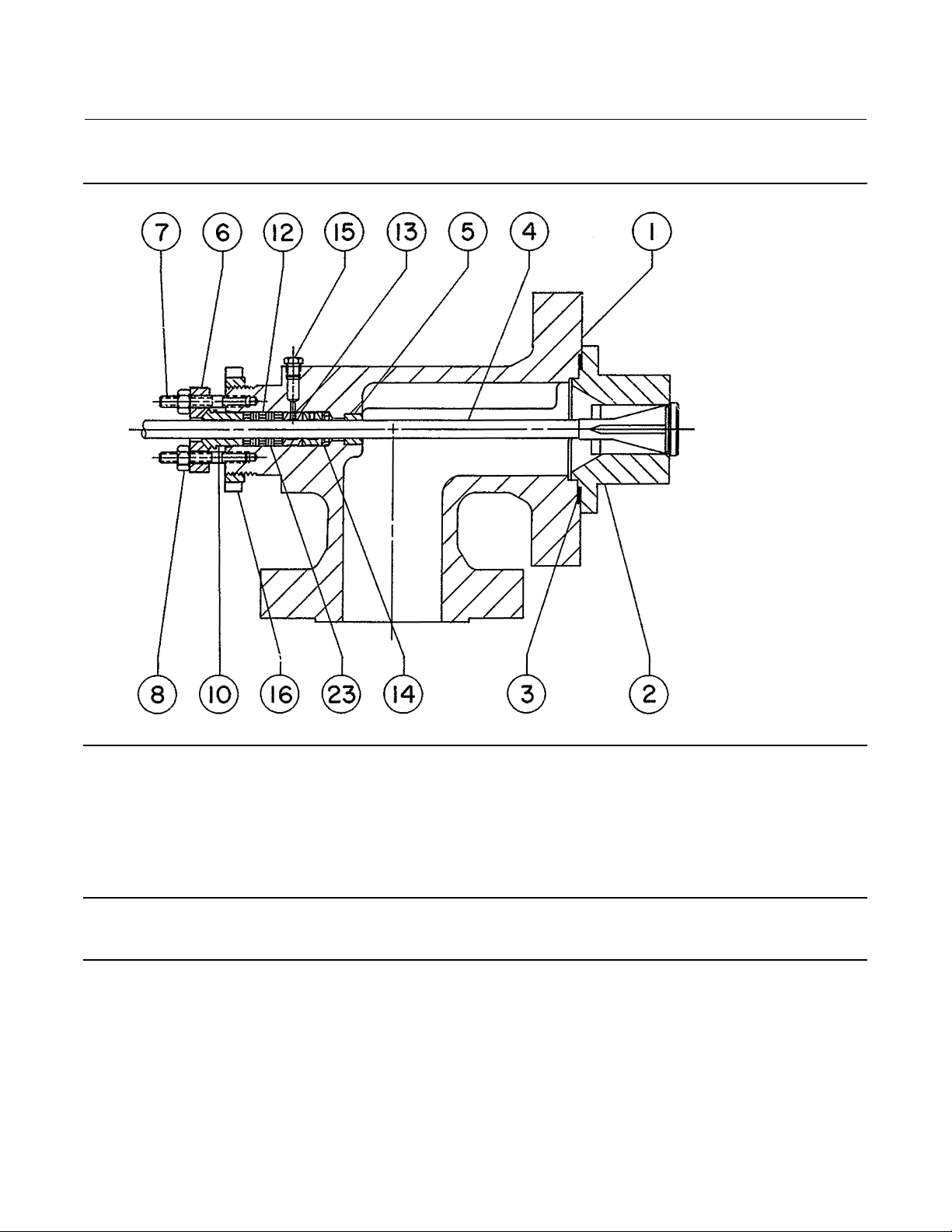
Figure 1. Fisher SS-83 Valve
Instruction Manual
D102030X012
15A1618-A
91 mm (3-9/16 INCH) YOKE BOSS
Packing Lubrication
Note
ENVIRO-SEAL or HIGH-SEAL packing does not require lubrication.
If a lubricator or lubricator/isolating valve is provided for PTFE/composition or other packings that require lubrication,
it will be installed in place of the pipe plug (key 15). Use a good quality silicon-base lubricant. Do not lubricate packing
used in oxygen service or in processes with temperatures over 260_C(500_F). To operate the lubricator, simply turn
the cap screw clockwise to force the lubricant into the packing box. The lubricator/isolating valve operates the same
way,exceptopentheisolatingvalvebeforeturningthecapscrewandthenclosetheisolatingvalveafterlubricationis
completed.
4
 Loading...