

Manuals & Guides: FIELDVUE DVC6200f Digital Valve Controller PST Calibration and Testing using ValveLink Software | Fisher
Fisher Manuals & Guides: FIELDVUE DVC6200f Digital Valve Controller PST Calibration and Testing using ValveLink Software | Fisher Manuals & Guides

Instruction Manual Supplement
D104217X012
DVC6200f Digital Valve Controller
Fisher™ FIELDVUE™ DVC6200f Digital Valve
Controller PST Calibration and Testing using
February 2017
ValveLink
The test procedure contained in this Instruction Manual Supplement is to be considered as a guideline only and should
be modified to address site‐specific requirements. Use this procedure in conjunction with the DVC6200 Series quick
start guide (D103556X012
engineering practices and abide by specific plant safety guidelines for safe operation.
For additional information on Partial Stroke Testing and associated parameters refer to Partial Stroke Test Information
on page 19.
™
Software
) and the DVC6200f instruction manual (D103412X012). In addition, exercise good
PST Calibration
This document covers the basic PST calibration, as well as details for making adjustments to the normal end, using
Advanced Settings (see figure 11).
Figure 1. Calibration > Partial Stroke
www.Fisher.com
Confirm PST Tier
DVC6200f Digital Valve Controller
February 2017
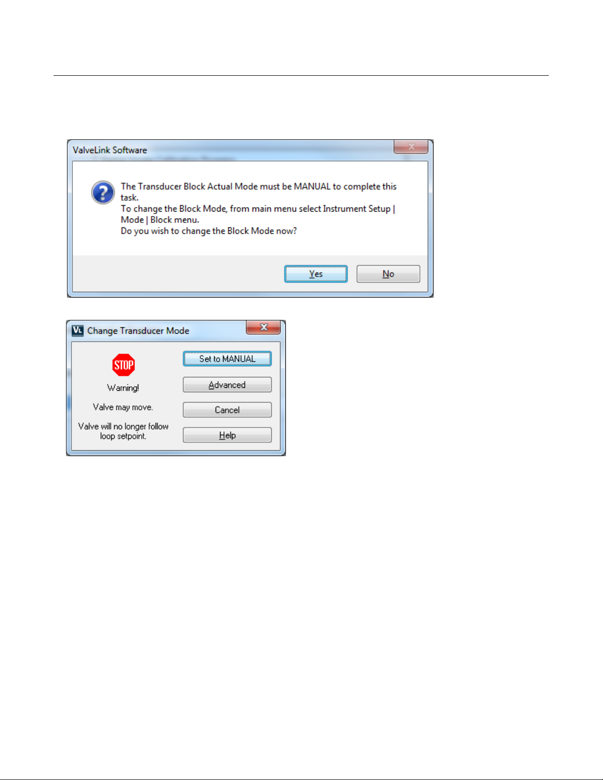
Figure 2. Set Transducer Block to Manual
Instruction Manual Supplement
D104217X012
2

Instruction Manual Supplement
D104217X012
Figure 3. Enter the Desire Outgoing Ramp Rate
DVC6200f Digital Valve Controller
February 2017
Supports separate ramp
rates for outing and
incoming strokes
Figure 4. Enter the Desired Incoming Ramp Rate
Additional ramp
rates for the
incoming stroke
3
DVC6200f Digital Valve Controller
February 2017
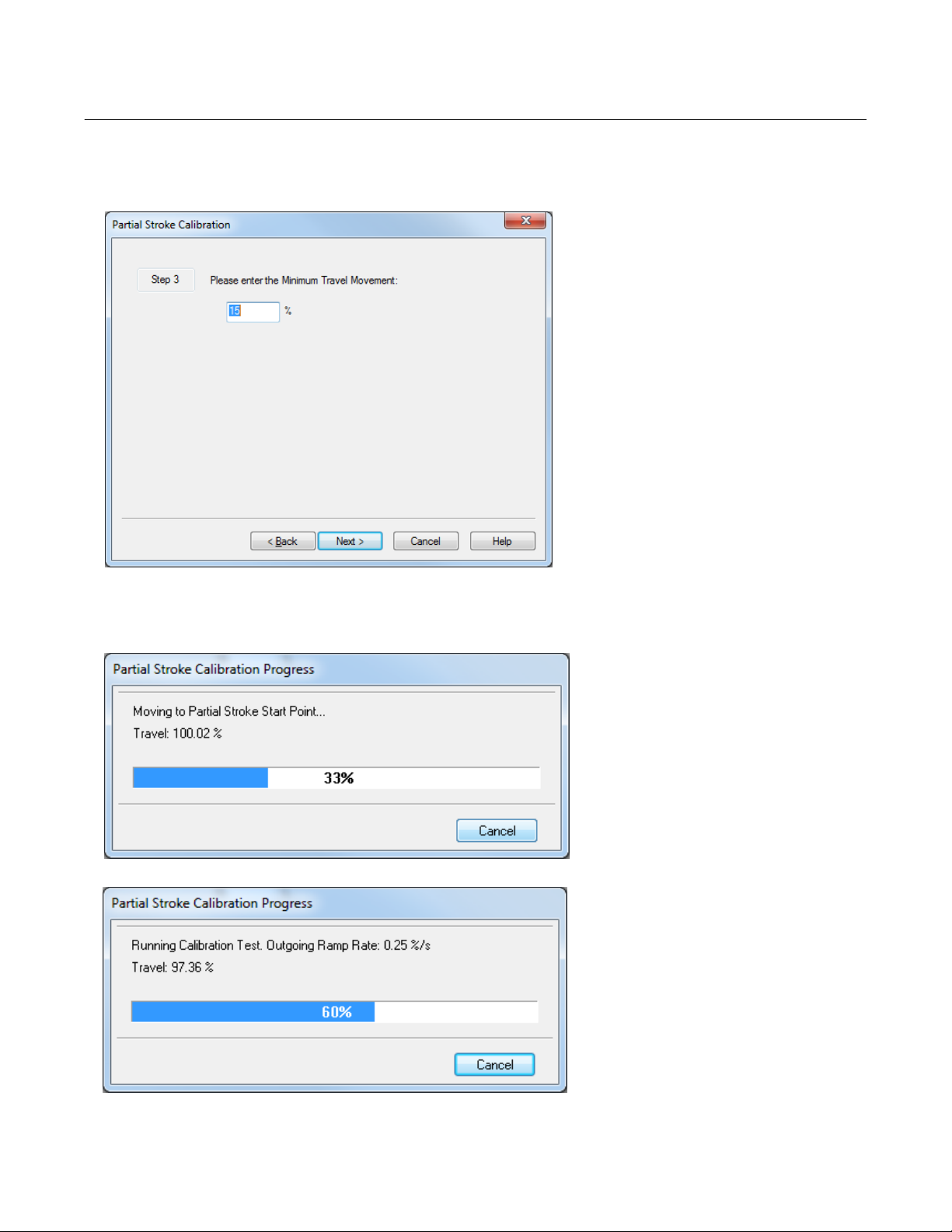
Figure 5. Enter the Minimum Travel Movement
Instruction Manual Supplement
D104217X012
Figure 6. Partial Stroke Calibration progress
4

Instruction Manual Supplement
D104217X012
Figure 7. Partial Stroke Calibration progress
DVC6200f Digital Valve Controller
February 2017
Will calibrate to 30% from the normal
end if the Minimum Travel Movement +
Set Point Over Drive is less than 30%
If it is greater than 30% the user-defined
point will be calibrated
Figure 8. Step or Ramp to Normal Position on Failed PST
5

DVC6200f Digital Valve Controller
February 2017
Figure 9. Partial Stroke Calibration Progress
Figure 10. Calibration Procedure Complete
Instruction Manual Supplement
D104217X012
List of parameter
values being
downloaded to
the device
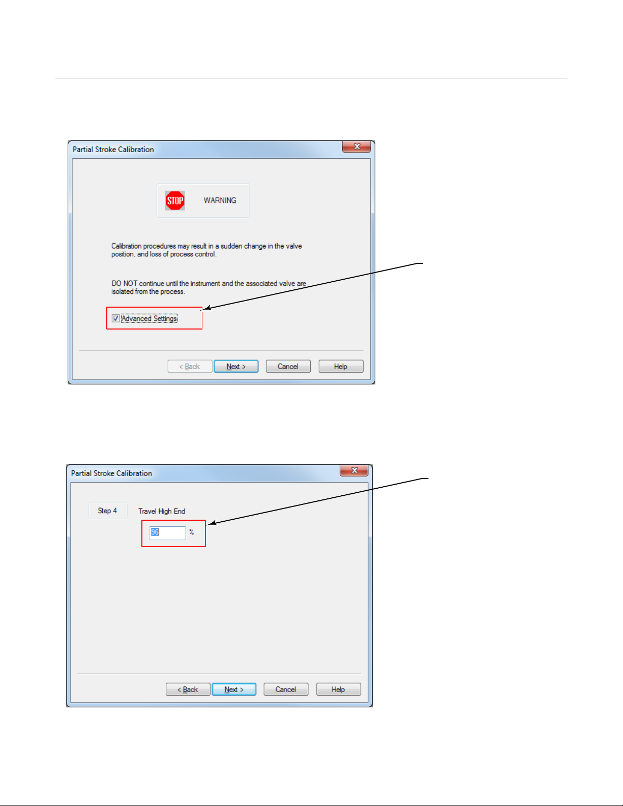
If you need to make adjustments to the normal end default settings, select Advanced Settings, as shown in figure 11,
and make the necessary adjustments.
6
Instruction Manual Supplement
D104217X012
Figure 11. Select Advanced Settings to Make Adjustments to the Normal End
DVC6200f Digital Valve Controller
February 2017
Select to define the
normal end
Figure 12. Set Travel High End
Defines the
end of travel
7
DVC6200f Digital Valve Controller
February 2017
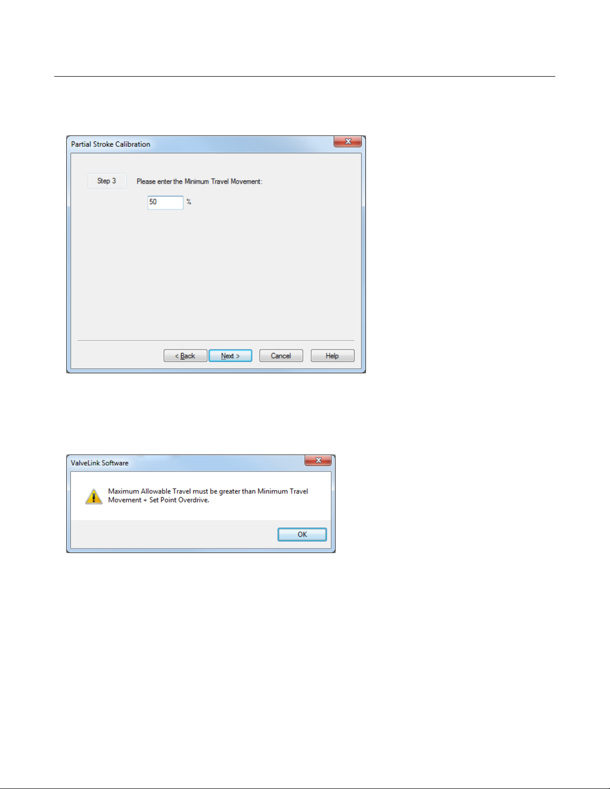
Figure 13. Enter Minimum Travel Movement
Instruction Manual Supplement
D104217X012
If Minimum Travel Movement + Set Point Overdrive is more than
Maximum Allowable Travel then the below message is presented
and you are directed to the next screen as shown in figure 14
8
 Loading...