

Manuals & Guides: Chemical Sourcebook Chapter 1 and 2: Ethylene Production Polysilicone Production | Fisher
Fisher Manuals & Guides: Chemical Sourcebook Chapter 1 and 2: Ethylene Production Polysilicone Production | Fisher Manuals & Guides

Chapter 1
Ethylene Production
NOTE: The following chapter is the
first of many to be released as part
of a Chemical sourcebook. These
chapters will be released to eDocs
as they are completed and when
fully developed, compiled into one
sourcebook.
Ethylene is one of the most important
petrochemical intermediates and is a feedstock for
many various products. End products made with
ethylene include food packaging, film, toys, food
containers, bottles, pipes, antifreeze, carpets,
insulation, housewares, etc. Chemicals that are
made from ethylene in order to produce these end
products are polyethylene, ethylene dichloride,
ethylene oxide, ethylbenzene, and vinyl acetate,
just to name a few.
Global ethylene capacity utilization has remained
above 90% since 2004 until 2008's economic
meltdown. In 2007, 2 million tonnes per year (tpy)
of ethylene capacity was added, according to the
Oil & Gas Journal. As of January 1, 2009, global
capacity was 126.7 million tpy. Capacity has been
added in recent years due to expansions and
debottlenecking at existing plants, as well as
greenfield plants being built in the Middle East and
Asia. Due to the change in market conditions and
the economy, there is an over‐supply of ethylene
capacity. Many plants have been taken offline in
this time period, are operating at reduced rates, or
are undergoing turnarounds. As the ethylene
market rebounds, capacity will increase. In fact,
based on new capacities announced and plants
that are under construction, global ethylene
capacity is expected to be at 162 million tpy by
2012, ahead of the demand growth.
There are five major licensors of ethylene plants:
KBR; Technip; Linde; Shaw, Stone & Webster;
and Lummus. While ethylene production differs
slightly by licensor, the overall process is fairly
similar (see Figure 1‐1). There are also some
differences in the process coming from the type of
feedstock being used. Some of these differences
will be highlighted. This chapter will cover the
general steps in ethylene production and will
discuss the critical valve applications within an
ethylene plant, what valve challenges those
applications present, and the recommended
Emerson solutions.
www.Fisher.com
Figure 1‐1. General ethylene process (naptha fed cracker)

Figure 1‐2. General ethylene furnace schematic
I. Furnace
The two primary feedstocks for ethylene
production are naphtha and natural gas (ethane,
propane, butane, etc.). The first step in the
production of ethylene is to take the feedstock and
crack it into ethylene and other various products in
a furnace. This process is called pyrolysis.
Pyrolysis is the thermal cracking of petroleum
hydrocarbons with steam, also called steam
cracking. The main types of commercial furnaces
are the ABB Lummus Global furnace, Millisecond
furnace (KBR), Shawt furnace (ultraselective
cracking furnace), Technip furnace, and the Linde
PYROCRACKt furnace. See Figure 1‐2 for a
general schematic of an ethylene furnace.
The feed hydrocarbon stream is pre‐heated by a
heat exchanger, mixed with steam, and then
further heated to its incipient cracking temperature
(932_F to 1256_F or 500_C to 680_C depending
upon the feedstock). At this point, it enters a
reactor (typically, a fired tubular reactor) where it is
heated to cracking temperatures (1382_F to
1607_F or 750_C to 875_C). During this reaction,
hydrocarbons in the feed are cracked into smaller
molecules, producing ethylene and co‐products.
products such as ethylene and propylene. Long
residence times will favor the secondary reactions.
Table 1‐1. Furnace Reactions
Primary Reactions
Feedstock/steam
Ethylene C4 products
Propylene C5 products
Acetylene C6 products
Hydrogen Aromatics
Methane C7 products
Etc.
Secondary
Reactions
Heavier
products
Maximum ethylene production requires a highly
saturated feedstock, high coil outlet temperature,
low hydrocarbon partial pressure, short residence
time in the radiant coil, and rapid quenching of the
cracked gas. Valves in the furnace section play a
critical role in maximizing ethylene production and
throughput.
There are three critical control valve applications in
the furnace area: dilution steam ratio control, feed
gas control, and fuel gas control. Each will be
discussed in further detail in the subsequent text.
The cracking reaction is highly endothermic,
therefore, high energy rates are needed. The
cracking coils are designed to optimize the
temperature and pressure profiles in order to
maximize the yield of desired or value products.
Short residence times in the furnace are also
important as they increase the yields of primary
1-2
Dilution Steam Ratio Control
The quantity of steam used (steam ratio) varies
with feedstock, cracking severity, and design of
the cracking coil. Steam dilution lowers the
hydrocarbon partial pressure, thereby enhancing
the olefin yield. Because of this, it is important to
obtain the appropriate ratio and maintain proper

control of that ratio. Steam helps to reduce coking
deposits by reacting with coke to form carbon
dioxide (CO
hydrogen (H
), carbon monoxide (CO), and
2
) and also reduces the catalytic effect
2
of the reactor coil's metal walls, which tend to
promote coke formation. An improper ratio
reduces efficiency of the cracker and can result in
the need for more decoking cycles, thus resulting
in less furnace uptime. It is necessary that
decoking be performed on a regular basis. This is
typically done by burning out the coke with a
mixture of steam and air. Time intervals for
decoking will depend upon several factors
including, but not limited to the type of furnace,
how the process is operated, feedstock type, and
the types of coils utilized.
Precise control of the steam dilution valve is
necessary to maintain the proper steam ratio,
which can greatly affect the efficiency of the
furnace. Due to the process conditions seen by the
dilution steam control valve, it requires the use of
graphite packing. Graphite packing often leads to
higher friction than one would see with the use of
PTFE packing. This added friction contributes to
high deadband and high variability, thus the loop
may become unstable. With high deadband and
variability, it's difficult to have precise control within
the valve, which leads to issues controlling the
loop. Due to the location of the valve (near the
furnace), high ambient temperatures are possible,
thus making the location a variable to consider
when selecting the actuator and related
accessories.
The Fisher
R
control valve solution for the dilution
steam ratio control valve is typically a Fisher
easy‐et sliding‐stem valve or a Fisher GX
sliding‐stem valve. Because of the friction
concerns mentioned previously, graphite ULF
packing is recommended. This packing meets the
process temperature requirements and has much
lower friction than standard graphite packing. A
spring‐and‐diaphragm actuator should also be
used as they are proven to provide precise control
in the field as well as in Fisher valve testing
facilities.
The use of a Fisher FIELDVUEt digital valve
controller with Performance Diagnostics (PD) can
be utilized to monitor control valve assembly
performance and allow for predictive maintenance.
When the performance is degrading, the next time
the furnace is brought down for maintenance
(typically decoking), valve maintenance can be
scheduled ahead of time to bring the valve
assembly back to an optimal performance level.
Feed Gas Control
The feed into an ethylene furnace can be ethane,
propane, butane, gas oil, or naphtha. Variation in
the type of feedstock used is related to availability.
Plants in the Middle East tend to use natural gas
feedstock because it is plentiful in the region and
is a low cost feedstock. Asia has a large
availability of naphtha and, therefore, is inclined to
use it more frequently as a feedstock. Plants can
also be designed to handle different types of
feedstocks, allowing them more flexibility to
change based upon availability and cost.
The feed gas control valve controls the flow of
feedstock used in the ethylene plant. Tight control
of the valve is critical in the steam dilution valve so
that the proper reaction ratio can be maintained
within the furnace. Control of the reaction ratio of
feedstock to steam will affect the reaction
efficiency and percentage of conversion to
ethylene. Due to the process conditions, the use of
graphite packing is required. Graphite packing
often leads to higher friction than with the use of
PTFE packing. This added friction contributes to
high deadband and high variability, thus the loop
may become unstable in automatic. With the high
deadband and variability, it's difficult to have
precise control within the valve, which then leads
to issues controlling the loop. Due to the location
of the valve (near the furnace), it can see high
ambient temperatures. This should be a
consideration when selecting the actuator and
related accessories. While most of these issues
mimic those of the steam dilution valve, there is an
additional variable to consider: the use of low
emission packing to reduce the emissions of the
feedstock for environmental and safety concerns.
The Fisher control valve solution for the feed gas
control valve is typically an easy‐e valve or GX
valve. Because of the friction concerns mentioned
and the desire to reduce emissions, use of Fisher
ENVIRO‐SEALt graphite ULF packing is
recommended. A spring‐and‐diaphragm actuator
should also be used as they are proven to provide
precise control in the field and in Fisher valve
testing facilities. A FIELDVUE digital valve
controller with PD can be utilized to monitor control
valve assembly performance and allow for
predictive maintenance. When the performance is
degrading, the next time the furnace is brought
down for maintenance (typically decoking), valve
maintenance can be scheduled ahead of time to
bring the valve assembly back to an optimal
performance level.
1-3

Fuel Gas Control
Fuel gas regulates the temperature of the furnace
by controlling the fuel to the burners. Special
temperature profiles are applied along the cracking
coil to avoid long residence times at low
temperatures. This is because low temperatures
favor the oligomerization reactions involved in the
formation of secondary products. Oligomerization
is a chemical process that converts monomers to a
finite degree of polymerization (i.e. products that
are not desirable in ethylene production). Because
special temperature profiles are applied, the
temperature control of the cracker is critical. The
goal is to maintain the optimum temperature in
order to favor the desired primary reactions and
produce the most ethylene possible.
Due to the nature of the fuel, many plants utilize
emissions control packing to limit the emissions of
the fuel gas. This is for environmental concerns as
well as general safety concerns. As with the other
valves in the furnace area, due to location, the fuel
gas valve may also see high ambient
temperatures. Depending upon on the ambient
temperatures for each particular application,
special care may need to be taken in selecting the
actuator and accessories.
Used with permission of Qenos Pty Ltd
Figure 1‐3. Quench tower
The Fisher control solution for the fuel gas control
valve is typically an easy‐e valve or GX valve. Due
to emissions concern, use of ENVIRO‐SEAL
graphite ULF packing is recommended. A
spring‐and‐diaphragm actuator should also be
used as they are proven to provide precise control
in the field and in Fisher testing facilities. A
FIELDVUE digital valve controller with PD can be
utilized to monitor control valve assembly
performance and allow for predictive maintenance.
When the performance is degrading, the next time
the furnace is brought down for maintenance
(typically decoking), valve maintenance can be
scheduled ahead of time to bring the valve
assembly back to an optimal performance level.
II. Quench Tower
Cracked gases leave the furnace at 1382_F to
1607_F (750_C to 875_C). The gases must be
cooled immediately in order to preserve the
current composition of the gas and prevent
undesirable side reactions from taking place.
These side reactions are generally the secondary
reactions listed in Table 1. The quench tower can
use either quench oil or quench water. Generally,
only quench water is used on natural gas‐based
systems whereas naphtha plants use quench oil
and may use a quench water tower as well.
For situations in which a quench oil tower is being
used for a naphtha fed plant, the quench oil is an
extremely erosive fluid. It is usually dirty with
entrained carbon particles. In order to have a
long‐lasting solution, the erosive nature of the fluid
must be taken into account when selecting an
appropriate valve.
The Fisher V500 eccentric plug rotary control
valve is a well‐suited solution for this application
as it was specifically designed to control erosive,
coking, and other hard to handle fluids. It should
be operated in the reverse flow position for erosive
service as this will help move the downstream
turbulence away from the shutoff surface. For the
quench oil application, a hardened trim should be
applied, either Alloy 6 or ceramic. Ceramic trim is
the typical solution. Sealed metal bearings are
available to help prevent particle buildup and valve
shaft seizure. The seat ring is reversible and will
help improve the lifetime of the construction.
1-4

W8359
Figure 1‐4. V500 eccentric plug
rotary control valve
III. Cracked Gas Compressor
After the cracked gas has been cooled in the
quench tower, the next step in the process is
cracked gas compression. A turbine driven
centrifugal compressor is utilized to perform this
compression and there are typically four to five
stages, with intermediate cooling. The number of
stages necessary depends primarily upon the
cracked gas composition and the temperature
level of the cooling medium. All of the throughput
of the ethylene plant will pass through a cracked
gas compressor, so performance and reliability of
this unit are especially important. The compressor
is also an extremely expensive piece of
equipment, resulting in a large percentage of the
overall capital of the plant.
An antisurge control system is designed to protect
this asset. The system is designed to provide a
faster response than adjusting the turbine speed to
control the onset of surge. The controller looks at
multiple variables to prevent the onset of surge. It
requires fast, accurate response in order to
prevent surge conditions. The characteristics of a
surge condition are fast flow reversal (measured in
milliseconds), excessive compressor vibration,
increase in flowing media temperature, noise, and
it may cause the compressor to “trip”.
Consequences of surge situations are substantial
and may include shortened compressor life, loss of
efficiency, reduced compressor output, and
mechanical damage to seals, bearings, impellers,
etc.
Antisurge control valves present many various
challenges. The key challenge is ensuring valve
reliability. There is an extended period between
W8950‐1
Figure 1‐5. Antisurge control system
maintenance cycles and it is important to ensure a
reliable control valve assembly solution. The
antisurge valve is the main piece of equipment that
protects the compressor from damage caused by
a surge. When these valves are called upon to
move, they are required to stroke very quickly,
typically in the open direction only. For example,
valves with travels up to 20 inches (50.8 cm) have
been required to stroke in as little as 0.75
seconds. This can necessitate oversized actuator
connections and the use of volume booster(s) and
quick exhaust valve(s). The improper selection of
these accessories will result in poor valve
performance and tuning difficulties. During a surge
event, the pressure drop and flow rate
experienced by the valve can be high, causing
excessive levels of noise. This must be considered
in valve selection, although noise control
throughout the entire range of valve travel may not
be required. This valve may also be required to
throttle intermittently from 0 to 100% open. These
cases require the valve to have fast, accurate
control for incremental step sizes. Any delays can
cause a surge to occur. The antisurge valve must
be able to pass the highest possible output
capacity of the compressor. Application of a
1-5

W6980
Figure 1‐6. WhisperFlo Trim cage
multiplying factor to the compressor capacity figure
is common and may lead to selection of an
oversized valve. Valves with too much capacity
often have controllability issues and can cause
unstable operation.
Emerson has developed an optimized antisurge
package to meet the challenging demands of this
application. Some highlights of this package will be
discussed, but for more information, please see
the brochure titled “Fisher Optimized Antisurge
Control Valves”. These valves use a spoked plug
versus the traditional balanced plug. With the
traditional plug, when the valve is asked to move
very quickly, there is not enough area in the
balance holes to keep the plug in a balanced state;
therefore, creating a differential pressure situation
between the top and the bottom of the plug. This
differential pressure case can lead to plug
instability. The spoked plug has large balance
areas so that this does not occur. For surge events
where noise is a concern, a Fisher valve with a
Whisper Trimt III or WhisperFlot trim is
recommended.
Emerson has the engineering capability to
characterize these trims in order to meet the
specific application needs and tailor a solution
towards them. For situations when the valve
assembly is called upon to move quickly,
mechanical air cushions have been added to the
actuator cylinder to provide controlled deceleration
to help protect actuator and valve components.
The Fisher optimized antisurge package also
includes a FIELDVUE digital valve controller with
the Optimized Digital Valve (ODV) tier. There are
features within this tier and ValveLinkt software
to meet the needs of the application. For example,
factory expertise is not required to tune the Fisher
optimized antisurge valve. A technician can simply
use ValveLink software's performance tuner or the
stabilize/optimize feature with real time graphics.
Configuration and tuning can also be performed
Figure 1‐7. Rich amine letdown system
remotely by operators as process requirements
change. This feature gives plant operators and
technicians the capability to tune this assembly in
the field. The lead‐lag filter in the ODV tier can be
used to improve the response to small amplitude
steps by overdriving the set point. Asymmetric
adjustments allow the response to be set
independently in the open and closing directions.
Integrated, real time graphics allow adjustments to
be done remotely as well. Also, diagnostics can be
collected, viewed, and analyzed using ValveLink
software to look at items such as packing friction,
air path leakage, actuator spring rate, and bench
set. Partial stroke tests can also be performed to
check the health of the valve and ensure the
antisurge valve is going to move when it is
requested to.
IV. Acid Gas Removal
The acid gas removal system is typically located
between the 3rd and 4th or between the 4th and
5th stages of the compressor. In all process
configurations, acid gas removal must be located
upstream of the drying unit in order to avoid
formation of ice and hydrates in the following
fractionation steps. Acid gases are typically
scrubbed on a once‐through basis or in
combination with a regenerative chemical.
Regenerative pre‐scrubbing, before a final sodium
hydroxide treatment, is applied for high sulfur
feedstocks. This will reduce the sodium hydroxide
consumption. Regenerative scrubbing can employ
alkanolamines. The use of alkanolamines should
then require the use of a rich amine letdown valve
as seen in Figure 1‐7.
After any free liquids are removed from the gas at
an inlet scrubber, the gas passes to the absorber
1-6

section. Here, it rises counter‐currently in close
contact with the descending amine solution.
Purified gas leaves from the top of the absorber.
Lean amine enters the tower at the top where it
flows across trays and downward against the flow
of the gas. At the bottom of the absorption tower,
the acid gas rich amine leaves through the rich
amine letdown valve that is actuated by a
liquid‐level controller. The rich amine then goes to
a flash tank, operating at a reduced pressure,
where large portions of the physically absorbed
gases are offgassed. From there, the rich amine
goes through various processes to be regenerated
and the cycle starts over again.
The rich amine letdown valve is a demanding
application because the process has entrained gas
in solution. As the fluid passes through the letdown
valve, it takes a pressure drop due to the pressure
differential between the tower and the flash tank.
As this pressure drop takes place in the valve, a
large amount of outgassing occurs. Outgassing is
when the entrained gas comes out of solution. As
a result of outgassing, the valve has a two phase
flow. One phase is the liquid amine and the other
and/or hydrogen sulfide (H2S) that comes
is CO
2
out of solution. This two‐phase flow may produce
excessive vibration and may be very erosive due
to high velocity impingement of the liquid phase on
the valve trim.
W0961
Figure 1‐8. Whisper Trim I cage
Outgassing is very similar in effect to flashing and
requires special consideration in the proper choice
of valve, trim style, and materials. Generally, the
overall approach is dependent on the severity of
the pressure drop experienced. Although some
sizing methods predict cavitation, small orifice
anti‐cavitation trim should not be used on this
service for two reasons: first, the vapor cushions
any cavitation bubble implosions and then
cavitation damage should not be experienced and
second, the accelerated gas breakout that, in turn,
accelerates the liquid, would rapidly erode the
multiple passage trim structure because of
incompressible fluid impingement.
For pressure drops of 300 to 600 psi (20.7 to 41.4
bar), use of slotted (Whisper Trim I) or drilled hole
(Whisper Trim III) trim styles installed in the flow
up direction are recommended. The slotted or
drilled hole cages “break up” the flow, minimizing
the potential energy available to be dissipated
during the outgassing process. Many relatively
small sources of energy do not possess the
damage capabilities of fewer large sources. By
flowing the process fluid up, these small sources
of energy are kept away from other critical trim
parts. Standard hardened cage, plug, and seat
W6787
Figure 1‐9. DST
parts are recommended. For pressure drops over
600 psi (41.4 bar), use of a slotted Whisper Trim I
cage made of solid Alloy 6 is recommended. A
hardened valve plug and seat ring should also be
used.
Other options for this condition include the use of a
Fisher NotchFlot Dirty Service Trim (DST) valve
or DST‐G trim designed for outgassing. For all rich
amine letdown applications, NACE materials are
likely specified.
V. Drying
The cracked gas is saturated with water before
compression and after each intercooler stage.
Moisture must be removed before fractionation to
prevent the formation of hydrates and ice.
Temperatures of -148_F (-100_C) would form ice
1-7
W9603
Figure 1‐10. DST‐G
compounds that could block pipes and/or damage
equipment. Typically this is accomplished by
chilling and by adsorption on molecular sieves.
The drying process is similar to that of a two bed
pressure swing adsorption (PSA) skid. Older
plants also use absorption by a glycol scrubbing
system or adsorption on alumina. Drying is
arranged before the first fractionation step,
typically after the last compression stage. Multiple
adsorption beds make continuous water removal
possible. One or more adsorption beds are in
operation while at least one unit is being
regenerated. The inability to dry because of
molecular sieve issues will shut down the plant.
Generally, line‐sized butterfly valves or
quarter‐turn ball valves are used in molecular
sieve switching valve applications. Over‐sizing can
occur and high cycle demands will cause wear on
the valves. As a result, galled bearings and seal
wear will also occur. In the case of high output
torque, bed lifting of the adsorption beads can
occur if the valve is controlling poorly or opens too
quickly and “jumps” out of the seat. This can
damage the adsorption beads and cause them to
rub or abrade together and create dust. This
reduces the drying effectiveness of the adsorption
beads. The dust or fines from bead wear can get
stuck in the bearing area and cause damage. At
the very worst, it can cause seizing of the valve.
The adsorption bead dust or fines can also cause
seal wear.
Emerson has experience and success in
molecular sieve applications for the ethanol
industry. Fisher A81 valves with a 316 SST
chrome plated disc and UHMWPE seal technology
Figure 1‐11. Molecular sieve drying system
A6163‐1
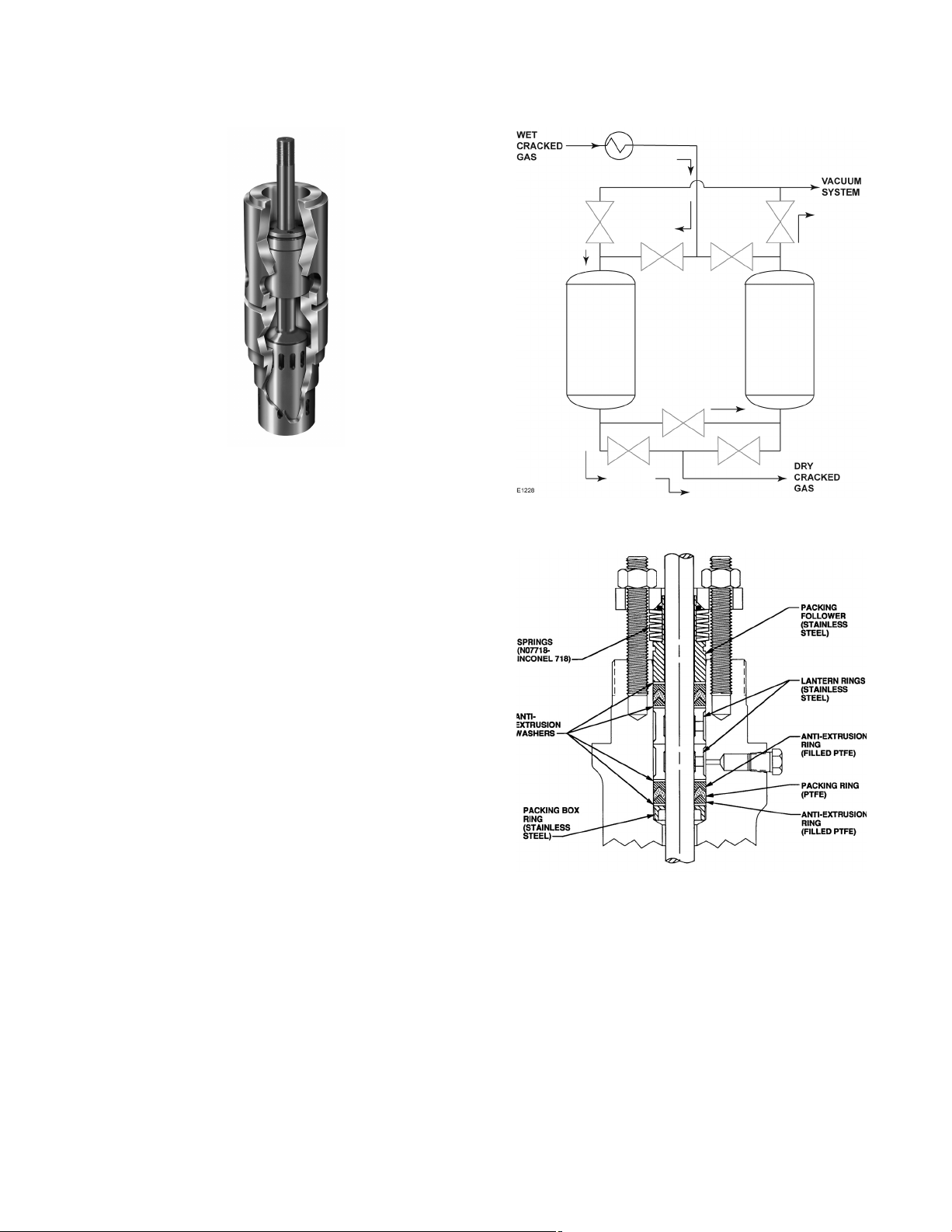
Figure 1‐12. ENVIRO‐SEAL PTFE packing system
have been used with good results. The UHMWPE
seal allows for tight shutoff. Tight shutoff allows for
improved bed drying. PTFE lined PEEK bearings
should also be used as these have been shown in
molecular sieve applications to last longer than
wire mesh bearings. ENVIRO‐SEAL packing may
also be considered to avoid leakage of the cracked
gas.
Use of a FIELDVUE digital valve controller can
increase the response to set point at the beginning
of the adsorption and regeneration cycle without
1-8

overshoot. It precisely controls the rate of opening
to eliminate adsorption bead bed disturbance.
VI. Distillation Columns
The fractionation section receives the compressed
cracked gas at a pressure of 464 to 551 psi (32‐38
bar) for further fractionation into different products
and fractions at specified qualities. This is done
through a series of distillation columns and
hydrogenation reactors. Cryogenic separation is
the predominant method for cracked gas
separation. Although gas separation processes via
adsorption, absorption, or membrane technology
have made progress in the recent past, they have
not found major applications within the ethylene
industry. Today, three processing routes have
gained commercial importance, with the main
characteristics being the first separation step and
the position of the acetylene hydrogenation. These
routes are demethanizer first with tail‐end
hydrogenation, deethanizer first with front‐end
hydrogenation, and depropanizer first with
front‐end hydrogenation. The following is a listing
of the various distillation columns and their
functions:
D Demethanizer: Demethanization of the
cracked gas separates methane as an overhead
component from C
components. Concurrently, hydrogen is removed
from the cracked gas stream and may be obtained
as a product by purification before or after
demethanization. Methane is typically used as a
plant fuel or sold. C
sent to the recovery system.
D Deethanizer: Deethanization of cracked gas
separates acetylene, ethylene, and ethane as
overhead components from C
components.
D Depropanizer: Depropanization separates
propane and lighter fractions as overhead
components from C
components.
splitter or ethylene fractionation: Ethylene
D C
2
fractionation separates ethylene as a high‐purity
overhead product from ethane, which is combined
with propane and recycled for cracking.
splitter or propylene fractionation:
D C
3
Propylene fractionation separates propylene as a
chemical grade overhead product or more
and heavier bottom
2
and heavier components are
2
+ bottom
3
+ fractions as bottom
4
frequently as polymer grade propylene from
propane. Propane is recycled for cracking.
D Primary fractionator: With liquid pyrolysis
feedstocks (naphtha fed plants), the primary
fractionation column is the first step in the cracked
gas processing route. Cracked gas enters the
column and it is contacted with circulating oil and,
at the top of the column, with a heavy pyrolysis
gasoline fraction obtained from the subsequent
water quench tower. Cracked gas leaves the top of
the primary fractionator free of oil but still
containing all the dilution steam. Hot oil, which
functions as a heat carrier, is collected at the
bottom of the column. After cooling, it is
recirculated as reflux to the middle section of the
primary fractionator and to the quench nozzles
downstream of the transfer line heat exchangers.
Distillation columns occur in all types of chemical
plants. The objective is to separate a feed stream
into light‐component and heavy‐component
product streams. It relies on the relative volatility
between the components that make up the feed
stream. The high volatility (lighter) components
boil at a lower temperature than the low volatility
(heavier) components. Therefore, when heat is
added to the column through a bottom reboiler, the
lighter materials are vaporized and rise to the top
of the column. The overhead vapors are cooled
until they condense and become a liquid again.
The efficiency of distillation depends on the
amount of contact between the vapor rising and
the liquid falling down the column. Therefore,
some of the overhead liquid product is sent back
(refluxed) to the top of the column. Increasing the
reflux will improve the purity of the overhead
product. However, it also requires more heat from
the reboiler to re‐vaporize the lighter components
in the reflux stream. Some distillation columns can
operate with a side reboiler as well, such as the
demethanizer. The operation of a distillation
column is a balancing act between product purity
and energy usage. If the amount of vapor and
liquid traveling through the column becomes too
great, the column can “flood.” Too much reflux, too
much reboil heat resulting in too much vapor, or
both can causing flooding. When flooding occurs,
the efficiency of the distillation column is
dramatically reduced with corresponding drops in
product purities.
Figure 1‐13 shows the general schematic of a
distillation column. The valves associated with this
are the feed, reflux, bottom product, overhead
product, pressure control, and reboil valves.
Feed valves are usually used as flow or level
control loops. An upstream unit or process often
1-9
 Loading...