

Instruction Manual: S208 and S209 Pressure Reducing Regulator with Internal Slam-Shut Device | Fisher
Fisher Instruction Manual: S208 and S209 Pressure Reducing Regulator with Internal Slam-Shut Device | Fisher Manuals & Guides

Instruction Manual
Form 5412
July 2012
Types S208 and S209
Types S208 and S209 Pressure Reducing Regulators
with Internal Slam-Shut Device
WARNING
!
Failure to follow these instructions or
to properly install and maintain this
equipment could result in an explosion
and/or re causing property damage
and personal injury or death.
Fisher® regulators must be installed,
operated, and maintained in accordance
with federal, state, and local codes,
rules and regulations, and Emerson
Process Management Regulator
Technologies, Inc. (Regulator
Technologies) instructions.
If the regulator vents gas or a leak
develops in the system, service to
the unit may be required. Failure
to correct trouble could result in a
hazardous condition.
Call a gas service person to service
the unit. Only a qualied person must
install or service the regulator.
Introduction
Scope of the Manual
W7876
Figure 1. Type S208K Pressure Reducing Regulator with
Type VSX-2 Slam-Shut Device
internal relief to allow overpressure caused by thermal
expansion to be released. The Types S208 and S209
include a Type VSX-2 integral slam-shut device. The
Type VSX-2 is a shut-off device that provides over
or over and underpressure protection by completely
shutting off the ow of gas to the downstream system.
The slam-shut device’s actions are independent of
the Types S208 and S209 regulators and of variations
to inlet pressure. The Type VSX-2 has internal
registration, except on the Type S208P or S209P where
a downstream sensing line is required.
This instruction manual provides installation,
adjustment, maintenance, and parts ordering
information for Types S208, S208H, S208P, S208PK,
S209, S209H, S209P, and S209PK gas service
regulators with Type VSX-2 integral slam-shut device.
Description
Types S208 and S209 regulators are typically installed
on industrial and commercial applications. Types S208
and S209 are similar in design to the Types S201 and
S202 regulators. Type S209 units contain a token
www.fisherregulators.com
Specications
The Specications section lists the ratings, pressure
ranges, and other specications for all Types S208 and
S209 regulators. The following information is stamped
on the regulator nameplate at the factory: type
number, manufacture date, spring range, orice size,
Type VSX-2 high and low trip pressures, maximum
inlet pressure, maximum outlet operating pressure,
and outlet pressure that may damage regulator parts.
D102247X012

Types S208 and S209
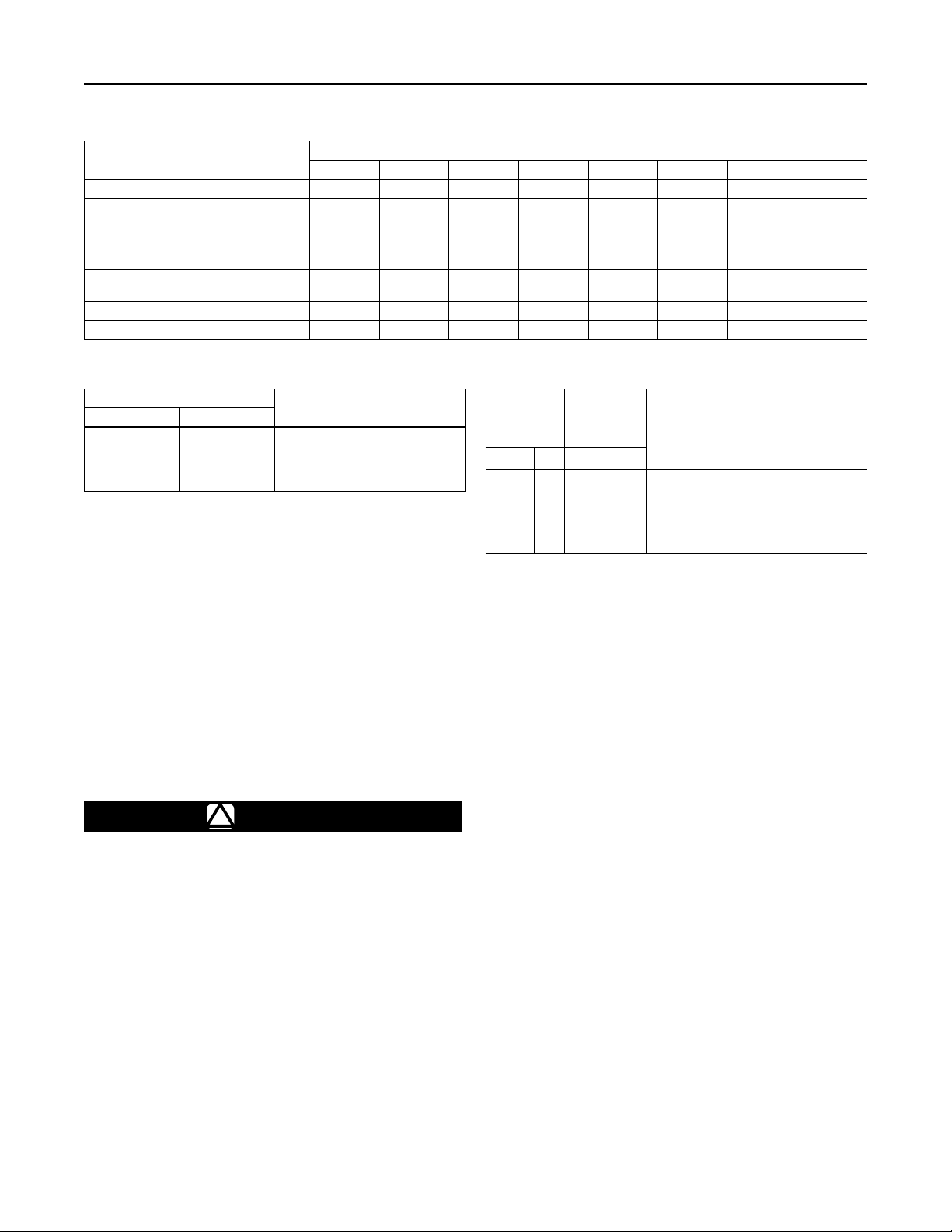
Specications
Available Congurations
See Table 1
Body Sizes and End Connection Styles
See Table 2
Maximum Inlet Pressure (Body Rating)
(1)
150 psig / 10.3 bar
Maximum Operating Inlet Pressure to Obtain
Optimum Performance by Orice Size
See Table 3
Maximum Outlet Pressure (Casing)
(1)
15 psig / 1.0 bar
Maximum Operating Outlet Pressure To Avoid
Internal Part Damage
(2)
Light Diaphragm Plate: 2 psi / 0.14 bar above
outlet pressure setting
Heavy Diaphragm Plate: 3 psi / 0.21 bar above
outlet pressure setting
Outlet Pressure Ranges
See Table 4
1. The pressure/temperature limits in this Instruction Manual and any applicable standard limitation should not be exceeded.
Type VSX-2 Trip Pressure Ranges
See Table 5
Pressure Setting Adjustment
Adjusting Screw
Pressure Registration
See Table 1
Material Temperature Capabilities
Nitrile (NBR): -20 to 150°F / -29 to 66°C
Fluorocarbon (FKM): 0 to 200°F / -18 to 93°C
(Upper temperature limitation due to
Nylon (PA) appers)
Type VSX-2: -20 to 140°F / -29 to 60°C
Control and Sensing Line Connections
(required on the “P” version only)
Types S208 and S209: 3/4 NPT
Type VSX-2: 1/4 NPT
Approximate Weight
30 pounds / 14 kg
(1)
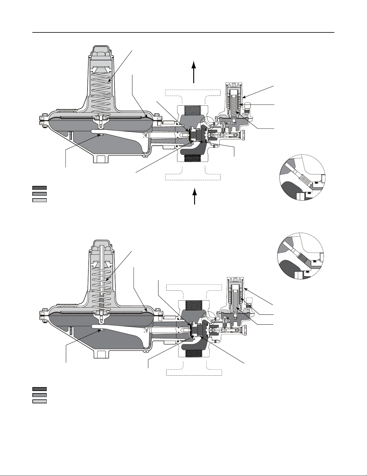
Principle of Operation (Figure 2)
Types S208 and S209
When the downstream demand decreases, the
pressure under the diaphragm increases. This
pressure overcomes the regulator setting (which is
set by a spring). Through the action of the pusher
post assembly, the valve disk moves closer to the
orice and reduces gas ow. If demand downstream
increases, pressure under the diaphragm decreases.
Spring force pushes the pusher post assembly
downward, the valve disk moves away from the orice,
and the gas ow increases.
The Type S209 regulators include a limited capacity
internal relief valve for relief of thermal expansion. If the
downstream pressure exceeds the regulator setting by
8 inches w.c. to 2 psig / 20 mbar to 0.14 bar, depending
on the main spring used, the relief valve opens and
excess gas is vented through the stabilizer vent in the
upper spring case.
Type VSX-2 Slam-Shut Device
The Type VSX-2 slam-shut device on the Types S208
and S209 regulators is a fast acting shut-off valve which
provides over or over and underpressure protection by
completely shutting off the ow of gas to the downstream
system. The shutoff module’s actions are independent
of the Types S208 and S209 regulators and variations
to the inlet pressure. The Type VSX-2 has internal or
external registration. External registration requires a
downstream sensing line.
The shutoff disk is held in the open position (reset
position) by a small ball holding the disk stem. If
the pressure below the diaphragm increases (or
decreases) reaching the Type VSX-2 setpoint,
the diaphragm will travel upwards (or downwards)
operating a level which in turn releases the ball.
Once the ball is released, the spring force on the stem
will push the stem and disk to the closed position
against the seat shutting off all gas ow. The manual
reset has an internal bypass to equalize the reset
pressure on either side on the shut-off disk.
2
Type S208
July 2008
Type S208
Type VSX-2 with
External Registration
Type VSX-2 with
Internal Registration
Type S208
Type S209
Type S208
Type VSX-2 with
PUSHER POST ASSEMBLY
E0234
INLET PRESSURE
OUTLET PRESSURE
ATMOSPHERIC PRESSURE
CONTROL SPRING
DIAPHRAGM
VALVE DISK
ORIFICE
TYPE S208
Types S208 and S209
TYPE VSX-2 MODULE
HIGH CONTROL SPRING
LOW CONTROL SPRING
ORIFICE INSERT
AND O-RING
TYPE VSX-2 WITH EXTERNAL
REGISTRATION
PUSHER POST ASSEMBLY
B2507
INLET PRESSURE
OUTLET PRESSURE
ATMOSPHERIC PRESSURE
CONTROL SPRING
DIAPHRAGM
VALVE DISK
ORIFICE
TYPE S209
TYPE VSX-2 WITH INTERNAL
REGISTRATION
TYPE VSX-2 MODULE
HIGH CONTROL SPRING
LOW CONTROL SPRING
ORIFICE INSERT AND O-RING
Figure 2. Operational Schematics
3
Types S208 and S209
Table 1. Available Congurations
CONSTRUCTION FEATURES
Light diaphragm plate X X
Heavy diaphragm plate X X X X
Either light or heavy diaphragm plate
depending on outlet pressure range
Internal registration X X X X X
External registration - O-ring stem seal and
downstream control line connection
Internal relief - Token X X X
Type VSX-2 X X X X X X X X
S208 S208H S208K S208P S208PK S209 S209H S209P
Table 2. Body Sizes and End Connection Styles
BODY SIZE
NPS DN
1-1/4, 1-1/2, or
1-1/2 x 2
2 50
32, 40, or 40 x 50 NPT
END CONNECTION STYLE
NPT, CL125 FF anged, CL250 RF
anged, or PN 10/16 RF anged
In order for the Underpressure Shutoff (UPSO) of
any slam shut to be triggered, the downstream pipe
pressure must drop below the UPSO setpoint. In the
case of a downstream line break, numerous factors
can prevent the downstream pipe pressure from
decreasing below the slam-shut UPSO setpoint. These
factors include the distance of pipe to the break, the
diameter of the pipe, size of the break, and the number
of restrictions, such as valves, elbows and bends,
downstream of the regulator and/or slam-shut device.
Due to these factors additional protections should be
installed to stop ow in the event of a line break.
WARNING
!
Personal injury or system damage
may result if this regulator is installed,
without appropriate overpressure
protection, where service conditions
could exceed the limits given on
the regulator nameplate. Regulator
installations should be adequately
protected from physical damage.
All vents should be kept open to permit
free ow of gas to the atmosphere. Protect
openings against entrance of rain, snow,
insects, or any other debris that may
plug the vent or vent line. On outdoor
installations, point the spring case vent
TYPE NUMBER
X X
X X X
Table 3. Orice Sizes and Maximum Operating Inlet Pressures
MAXIMUM
6.4
9.5
13
19
25
30
OPERATING
INLET
PRESSURE
125
8.6
125
8.6
100
6.9
60
4.1
25
1.7
13
0.90
C
53
110
190
415
700
910
g
C
1.51
3.14
5.43
11.9
20
26
v
C
1
35
ORIFICE SIZE
Inches mm psig bar
1/4
3/8
1/2
3/4
1
1-3/16
downward to allow condensate to drain.
This minimizes the possibility of freezing
of water or other foreign material from
entering the vent and interfering with
proper operation.
Under enclosed conditions or indoors,
escaping gas may accumulate and be
an explosion hazard. In these cases,
the vent should be piped away from the
regulator to the outdoors.
If the regulator or slam-shut device is
exposed to an overpressure condition,
it should be inspected for any damages
that may have occured. Operation
below these limits does not preclude
the possibility of damage from external
sources or from debris in the pipeline.
In the case of a downstream line break,
numerous factors affect the capability to
evacuate gas from the pipeline. These
factors include the distance of pipe to the
break, the diameter of the pipe, size of
the break, and the number of restrictions,
such as valves, elbows and bends,
downstream of the regulator and/or
slam-shut device. Due to these factors
additional protections should be installed
to stop ow in the event of a line break.
4
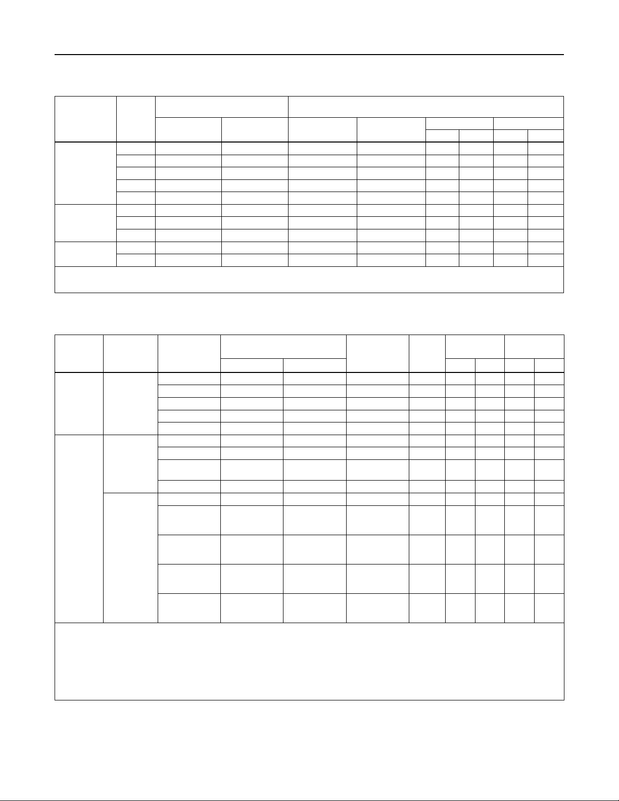
Table 4. Outlet Pressure Ranges
Types S208 and S209
TYPES
S208, S209,
S208P, and
S209P
OUTLET (CONTROL)
SPRING
NUMBER
- - - - 2 to 4.5
PRESSURE RANGE
Inch w.c. mbar Part Number Color Code
(1)
5 to 11
(1)
1D892527022 Brown Stripe 6.12 15.5 0.109 2.77
1 3.5 to 6.5 9 to 16 1D892627022 Red 7.5 19.1 0.120 3.05
2 5 to 9 12 to 22 1D892727012 Black 7.88 20.0 0.130 3.30
3 8.5 to 18 21 to 45 1D893227032 Gray 7.5 19.1 0.156 3.96
PILOT CONTROL SPRING
Free Length Wire Diameter
Inches cm Inches mm
4 14 to 30 35 to 75 1D893327032 Dark Green 7.25 18.4 0.182 4.62
5 1 to 2 psig 0.07 to 0.14 bar 1H975827032 Dark Blue 7.38 18.7 0.225 5.72
(2)
S208H, S208P
S209H, and
S209P
S208K and S208PK
1. With regulator installed so control spring is on top of diaphragm. If installed so control spring is on bottom, lower end of outlet pressure range can be reduced by 1-inch w.c. / 2 mbar
for regulator with light diaphragm plate or 2-inches w.c. / 5 mbar for regulator with heavy diaphragm plate.
2. Types S208P and S209P require heavy diaphragm plate for outlet pressures over 1 psig / 0.07 bar.
,
(2)
6 1.5 to 3.25 psig 0.10 to 0.22 bar 1H975927032 Orange 7.38 18.7 0.250 6.35
7 2 to 5 psig 0.14 to 0.34 bar 1P615427142 Yellow 6.5 16.5 0.283 7.19
8 2 to 5.5 psig 0.14 to 0.38 bar 0Y066427022 Green Stripe 6.00 15.2 0.363 9.22
9 4 to 10 psig 0.28 to 0.69 bar 1H802427032 Unpainted 6.00 15.2 0.406 10.31
Table 5. Type VSX-2 High and Low Trip Pressure Ranges
SETPOINT
RANGES
SLAM-SHUT
REGISTRATION
WITH MAIN
VALVE SPRING
NUMBER
(1,2)
1, 2 12 to 25 30 to 62 T14162T0012 Black 3.15 80.0 0.067 1.70
1, 2, 3, 4 20 to 52 50 to 129 T14163T0012 Brown 3.15 80.0 0.080 2.03
FOR USE
Overpressure
Shutoff
Internal or
External
3, 4, 5, 6 1.4 to 3.9 psig 0.10 to 0.27 bar T14164T0012 Red 3.15 80.0 0.091 2.31
5, 6, 7, 8, 9 3.8 to 8.7 psig 0.26 to 0.60 bar T14165T0012 Orange 3.15 80.0 0.120 3.05
9 5.8 to 16 psig 0.40 to 1.1 bar T14166T0012 Pink 3.15 80.0 0.138 3.51
2, 3 2 to 12 5 to 30 T14168T0012 White 3.15 80.0 0.043 1.09
3, 4, 5, 6 4 to 30 10 to 75 T14169T0012 Blue 3.15 80.0 0.055 1.40
External
5, 6, 7, 8
7, 8, 9 1.5 to 10.8 psig 0.10 to 0.75 bar T14171T0012 Olive 3.15 80.0 0.125 3.18
(3)
2, 3, 4
(4)
Underpressure
5, 6
Shutoff
(4)
5, 6, 7, 8
Internal
(4)
7, 8
(4)
9
1. See Table 4 for main valve spring number.
2. Other spring combinations are available, please contact your local Sales Ofce for additional information. Trip pressure that are 2 or 3 psig / 0.14 to 0.21 bar
over set pressure may result in internal parts damage.
3. Regulator main valve spring numbers 2, 3, and 4 cannot be used with an internally registered Type VSX-2 to provide underpressure shutoff under owing conditions. If protection
against loss of inlet pressure is the only required function for the Type VSX-2 then an internally registered Type VSX-2 may be used with the same minimum trip pressures as an
externally registered Type VSX-2.
4. 50% of regulator setpoint is the minimum allowable underpressure shutoff setting for an internally registered Type VSX-2 used with main valve spring numbers 5, 6, 7, and 8.
70% of regulator setpoint is the minimum allowable underpressure shutoff setting for an internally registered Type VSX-2 used with main valve spring number 9. If protection against
loss of inlet pressure is the only required function for the Type VSX-2 then an internally registered Type VSX-2 may be used with the same minimum trip pressures as an externally
registered Type VSX-2.
MINIMUM TO MAXIMUM
TRIP PRESSURE
Inch w.c. mbar Inches mm Inches mm
10 inches w.c.
to 2.3 psig
25 mbar to
0.16 bar
TYPE VSX-2
SPRING PART
NUMBER
SPRING
COLOR
T14170T0012 Silver 3.15 80.0 0.067 1.70
SPRING FREE
LENGTH
SPRING WIRE
DIAMETER
- - - - - - - - - - - - - - - - - - - - - - - - - - - - - - - - - - - - - - -
50% of regulator
setpoint to
30
50% of regulator
setpoint to
2.3 psig
50% of regulator
setpoint to
10.8 psig
70% of regulator
setpoint to
10.8 psig
50% of regulator
setpoint to
75
50% of regulator
setpoint to
0.16 bar
50% of regulator
setpoint to
0.75 bar
70% of regulator
setpoint to
0.75 bar
T14169T0012 Blue 3.15 80.0 0.055 1.40
T14170T0012 Silver 3.15 80.0 0.067 1.70
T14171T0012 Olive 3.15 80.0 0.125 3.18
T14171T0012 Olive 3.15 80.0 0.125 3.18
5
 Loading...