


Instruction Manual
MCK-1155
April 1981
Type N550
Type N550 Packing Removal/Replacement
WARNING
!
Only qualified servicemen should
attempt to repair these valves. The skill
required is similar to the complexity
involved in pump repair.
Before starting any type of repair, close
off the upstream valves and remove all
gas pressure from both the outlet and
inlet sides of the Type N550 emergency
shutoff valve (ESV).
Before Removing Packing
If the Type N550’s operating handle closes slowly or
binds in a “no flow” condition, it could be from binding in
the packing gland area or from external binding, such
as a bent operating handle catching on the latch block,
etc. Check for some type of external binding first.
If the binding appears to be internal, it could be from
uneven or over-tightened gland bolts (key 33), refer to
Figures 1 and 24. Try loosening these two bolts onehalf turn each, and tap the shaft (key 15) lightly side
to side to align the gland and follower bearing. Snug
the bolts down evenly, only tight enough to prevent
leakage. If this does not free the handle, the packing
must be removed and be either cleaned or replaced.
Removal of Packing
Refer to Figure 24.
Note
If there is leakage around the shaft
(key 15), the packing should be replaced.
Order parts kit T13090 which includes a
Figure 1. Uneven gland bolts could cause binding
graphite packing adaptor (black), a TFE
packing ring (white), a TFE male adaptor
(white), a gasket, and two washers
(key nos. 26, 29, & 30). With no leakage,
only binding, the packing probably can
be reused, and the only replacement
parts required are the gasket (key 26)
and washer (key 29). In either case, use
Magnalube G grease (part no. T13049,
1/2 oz. tube which will lubricate many
valves) of the regulator.
CAUTION
Throughout the entire removal and
replacement procedure, be sure that
the shaft (key 15) is not pulled out of
the internal lever holding the poppet
assembly. If the shaft is pulled out, the
D450042T012
R
www.FISHERregulators.com/lp
Type N550
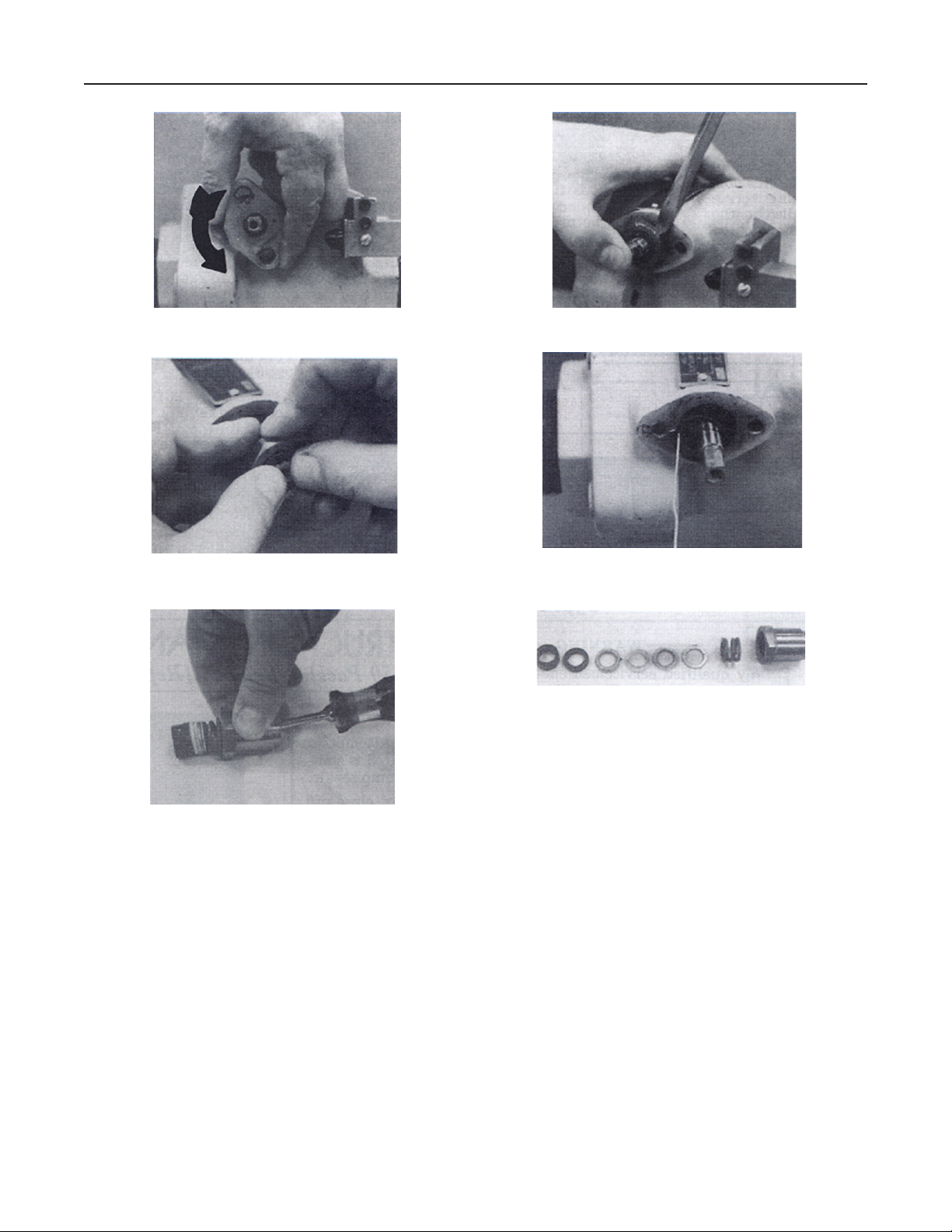
Figure 2. Turn gland retainer (step 3)
Figure 4. Remove gland (step 6)
Figure 3. Pry out gland (step 5)
Figure 5. Remove gasket (step 7)
Figure 7. Remove packing carefully (step 8)
Figure 6. Remove packing carefully (step 8)
N550 will have to be removed from the
line in order to properly reassemble it.
Holding the shaft in place permits the
valve to be left in-line if all line pressure
is removed.
1. Remove the operating handle (key 18), fuse
link assembly (key 22), and retainer (key 24) by
unscrewing the bolt (key 23).
2. Take out the two gland bolts (key 33).
3. Turn the gland retainer (key 32) one-half turn
counterclockwise, refer to Figure 2.
2
4. Remove the gland retainer from the gland (key 27).
5. Holding the valve’s shaft firmly in place, pry out
the gland with a screwdriver, Figure 3.
6. Still holding the shaft in place, work the gland
over the end of shaft to remove the gland, Figure 4.
7. The gasket (key 26) may be on the end of the
gland, but most likely it is still in the body. Use a stiff
wire (such as a paper clip), Figure 5 to remove the
gasket. The gasket should be discarded and a new
one used when reassembling.
8. Carefully remove the packing stack (key 30) from
the rear of the gland. Use a screwdriver, Figure 6, to
push between the coils of the spring (key 28) to avoid
cutting the packing or scratching the gland.
9. The part shown in Figure 7 will be removed from
the gland: follower bearing (key 31), packing stack

Type N550
(key 30), includes graphite female adaptor, two TFE
packing rings, and a TFE male adaptor), a washer
(key 29), and the packing spring (key 28).
10. Clean the packing (if it is to be reused), the
gland, and the shaft of dirt, grease, and paint.
CAUTION
Paint on the shaft may damage
the packing.
Reassembly of Packing
Figure 8. Replacement parts for gland
Refer to Figure 25.
Note
4. Lubricate the shaft, gland, packing, and follower
bearing with a liberal amount of Magnalube G grease,
Figure 12.
5. Replace the male TFE packing adaptor with the
flat side in
into the gland. Be careful not to damage this adaptor.
Apply a liberal amount of Magnalube G grease on the
face of this adaptor, Figure 14, so that it will be trapped
under the next ring.
6. Install one TFE packing ring with the
in, Figure 15, using the same procedure as in step 5.
Again apply a liberal layer of Magnalube G grease.
7. Install the graphite adaptor flat side out, Figure 16.
8. Install the follower bearing and press it in place with
the gland retainer, Figure 17. The bearing will extend
about 1/8-inch (3,2 mm) from the gland, Figure 18.
9. Install the gland retainer over the gland. Turn the
retainer about one-quarter turn clockwise Figure 19,
then let the spring turn the gland back until it stops.
10. Remove the retainer and fit it back on the
gland so that the bolt holes line up as closely as
possible with bolt holes in the body, Figure 20.
11. Wind the gland retainer
and install the bolts (key 33), Figure 21.
, Figure 13, working it over the shaft and
female side
one-half turn clockwise
The parts shown in Figure 8 are to be
replaced in the gland: packing spring
(key 28), two washers (key 29), packing
stack (key 30) includes graphite female
adaptor one TFE packing ring, and a
TFE male adaptor), and the follower
bearing (key 31).
1. Install a new gasket (key 26) on the step at the
back of the gland (key 27). Note the small hole on the
back of the gland, Figure 9. This hole must engage
the end of the closing spring (key 25) when the gland
is installed in the body. Look in the body and note the
position of the end of the closing spring, Figure 10.
2. Insert the gland into the body, and slowly turn the
gland while pushing it into place. When the closing
spring snaps in the gland’s hole, the gland fits in the
body as deeply as it had originally.
3. Install the packing spring and the two washers into
the gland, Figure 11.
Note
Winding the retainer tightens the closing
spring. If the spring is wound more than
one-half turn, It may bind and pull the
end out of the gland when the valve is
opened. If not wound enough, the valve
may be sluggish on closing.
12. Install the handle assembly (key nos. 18,
22, 23, and 24), Figure 22, and carefully open the
valve. If there is binding before the handle goes fully
open, the closing spring has been wound too tightly.
Repeat steps 9-11 to get the proper spring winding
before proceeding.
13. If the handle moves freely to the open position,
tap the shaft lightly side to side, Figure 23, to align the
follower bearing. The valve should now the be ready
for service.
14. Carefully repressure the line and check for leaks.
3
 Loading...