

Fisher Instruction Manual: HIGH-SEAL ULF Live-Loaded Packing System | Fisher Manuals & Guides
Instruction Manual
D101453X012
HIGH-SEAL Live-Loaded Packing
HIGH‐SEAL ULF Live‐Loaded Packing System
July 2017
Contents
Introduction 1.................................
Scope of Manual 1.............................
Description 2.................................
Spring Selection 3.............................
Installation 3..................................
Parts Ordering 6................................
Retrofit Parts 7.................................
Parts List 8....................................
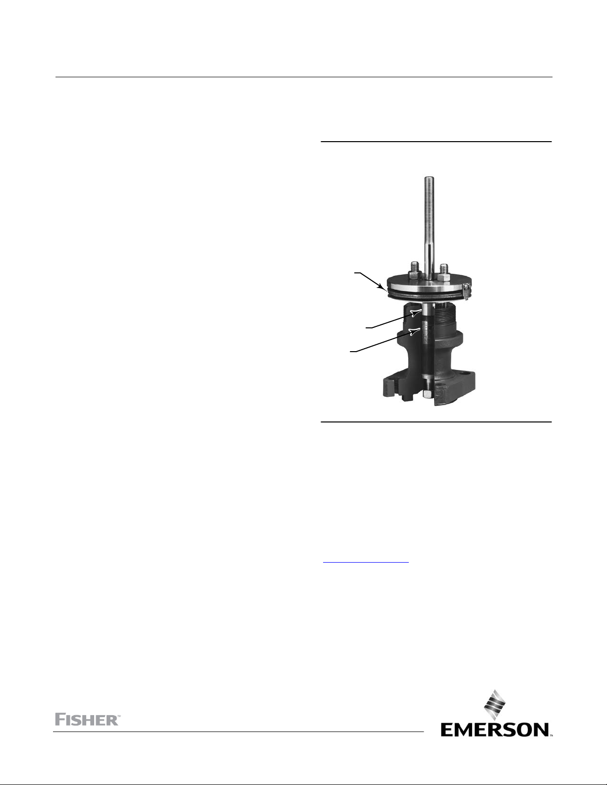
Figure 1. HIGH‐SEAL ULF Live‐Loaded Packing
System
SPRING
PACKING
FOLLOWER
PACKING
RINGS
W5784
Introduction
Scope of Manual
This instruction manual includes installation, maintenance, and parts information for HIGH‐SEAL ULF live‐loaded
packing systems (see figure 1). These systems are available for sliding‐stem valves with 9.5, 12.7, 19.1, 25.4, 31.8 and
50.8 mm (3/8, 1/2, 3/4, 1, 1‐1/4, and 2‐inch) stem diameters. Refer to separate manuals for instructions covering
valves and actuators. For rotary valve applications, contact your Emerson sales office
to your rotary valve instruction manual.
Do not install, operate, or maintain HIGH‐SEAL ULF live‐loaded packing systems without being fully trained and
qualified in valve, actuator, and accessory installation, operation, and maintenance. To avoid personal injury or
property damage, it is important to carefully read, understand, and follow all the contents of this manual, including all
www.Fisher.com
or Local Business Partner or refer
HIGH-SEAL Live-Loaded Packing
July 2017
Instruction Manual
D101453X012
safety cautions and warnings. If you have any questions about these instructions, contact your Emerson sales office or
Local Business Partner before proceeding.
Description
HIGH‐SEAL ULF live‐loaded packing systems combine the excellent sealing performance of the ENVIRO‐SEAL Graphite
ULF packing set with the high‐performance of the HIGH‐SEAL spring pack. The long‐travel HIGH‐SEAL Belleville springs
accurately compensate for any packing consolidation or wear, keeping the packing stress nearly constant over the life
of the packing set.
The HIGH‐SEAL load scales ensure accurate initial packing adjustment and provide positive visual indication of the
packing stress at any time. It is recommended that new packing sets be adjusted to the MAX level.
HIGH‐SEAL ULF packing systems are intended for more‐severe applications with pressure limits up to 290 bar (4200
psig), except for 9.5 mm (3/8 inch) stem size, which is restricted to 110 bar (1600 psig). If your application exceeds
these limits, consult your Emerson sales office or Local Business Partner. For ratings on packing systems, refer to
59.1:062 Packing Selection Guidelines For Sliding Stem Valves (D101986X012
pressure/temperature limits of the valve. If the piping and valve are insulated, do not allow insulation to extend above
the yoke boss surface, covering the HIGH‐SEAL ULF packing arrangement. Keep the HIGH‐SEAL ULF packing
arrangement exposed to ambient air conditions.
). However, do not exceed the
Table 1. Packing Friction with HIGH‐SEAL Graphite ULF Packing
VALVE STEM DIAMETER
mm Inches
Newtons
9.5
12.7
15.9
19.1
25.4
31.8
50.8
9.5
12.7
15.9
19.1
25.4
31.8
50.8
3/8
1/2
5/8
3/4
1
1‐1/4
2
Pounds (Force)
3/8
1/2
5/8
3/4
1
1‐1/4
2
HIGH‐SEAL GRAPHITE ULF PACKING
935
1250
1680
2350
3740
4800
6000
210
230
380
530
840
1100
1350
The flange, Belleville springs, stud bolts and nuts, packing follower, and packing arrangement are an integral part of
the HIGH‐SEAL ULF system (see figure 6). For maximum packing life and to operate within the friction specified in table
1, do not interchange any other packing parts with the parts in the HIGH‐SEAL ULF system.
WARNING
HIGH‐SEAL ULF live‐loaded packing systems are intended for a specific range of pressure, temperature and other service
conditions. The valves for which these packing systems are available are also intended for a specific range of pressure,
temperature and other service conditions. Do not expose the packing system or the valve to service conditions or variables
other than those for which the packing system and valve are intended. If you are not sure what these conditions are,
contact your Emerson sales office or Local Business Partner. Provide the product serial number (shown on the nameplate)
and all other pertinent information. Applying different conditions could result in parts damage, malfunction of the valve or
loss of control of the process, and could also result in personal injury or property damage.
2
Instruction Manual
D101453X012
HIGH-SEAL Live-Loaded Packing
July 2017
Spring Selection
The Belleville springs for HIGH‐SEAL ULF systems are rated by stem size (see table 1). Available materials for the
Belleville springs are S17700 (17‐7 PH stainless steel) and N07718.
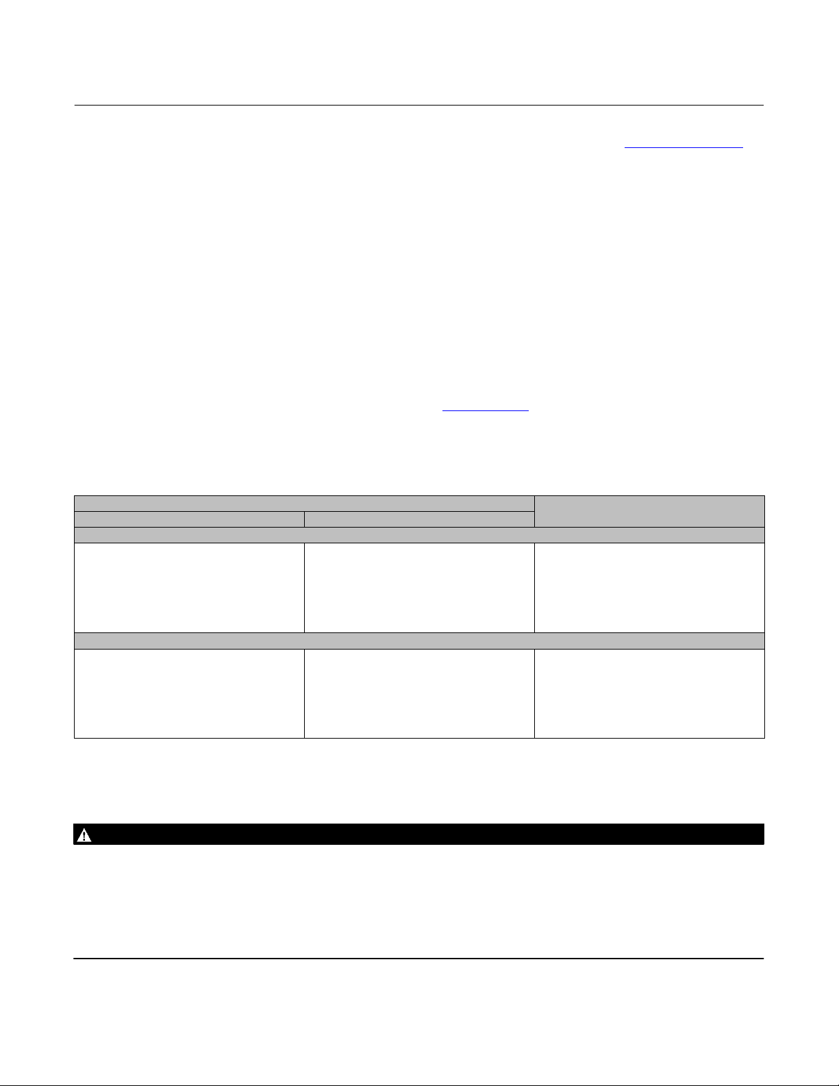
It is important to match the appropriate load scale (see figure 2) to the stem size of the valve. Stem size is stamped on
the load scale.
Figure 2. Typical Load Scale
STEM SIZE
MAXIMUM SPRING LOAD
MINIMUM SPRING LOAD
ZERO SPRING LOAD
(PACKING NUTS FINGER‐TIGHT)
A4990‐2
Installation
HIGH‐SEAL ULF packing systems are designed for quality performance over extended periods. This longevity allows
packing maintenance to be performed as it should be, at regularly scheduled plant outages or turn‐arounds.
WARNING
Avoid personal injury from sudden release of process pressure. Before performing any maintenance operations:
D Do not remove the actuator from the valve while the valve is still pressurized.
D Always wear protective gloves, clothing, and eyewear when performing any maintenance operations to avoid personal
injury.
D Disconnect any operating lines providing air pressure, electric power, or a control signal to the actuator. Be sure the
actuator cannot suddenly open or close the valve.
D Use bypass valves or completely shut off the process to isolate the valve from process pressure. Relieve process pressure
from both sides of the valve. Drain the process media from both sides of the valve.
D Vent the power actuator loading pressure and relieve any actuator spring precompression.
D Use lock‐out procedures to be sure that the above measures stay in effect while you work on the equipment.
D The valve packing box may contain process fluids that are pressurized, even when the valve has been removed from the
pipeline. Process fluids may spray out under pressure when removing the packing hardware or packing rings, or when
loosening the packing box pipe plug.
D Check with your process or safety engineer for any additional measures that must be taken to protect against process
media.
3
HIGH-SEAL Live-Loaded Packing
July 2017
Instruction Manual
D101453X012
If the valve is in service, isolate the control valve from the line pressure, release pressure from both sides of the valve
body, and drain the process media from both sides of the valve. If using a power actuator, also shut off all pressure
lines to the power actuator and release all pressure from the actuator. Use lock‐out procedures to be sure that the
above measures stay in effect while you work on the equipment. Refer to instructions in the appropriate valve and
actuator instruction manuals.
If you are installing the HIGH‐SEAL ULF packing system in a valve that is still connected to an actuator, it will be
necessary to disconnect the valve from the actuator to provide sufficient space to install the packing assembly. Refer
to appropriate valve and actuator instruction manuals. Remove old packing parts from the packing box by using the
valve instruction manual procedures.
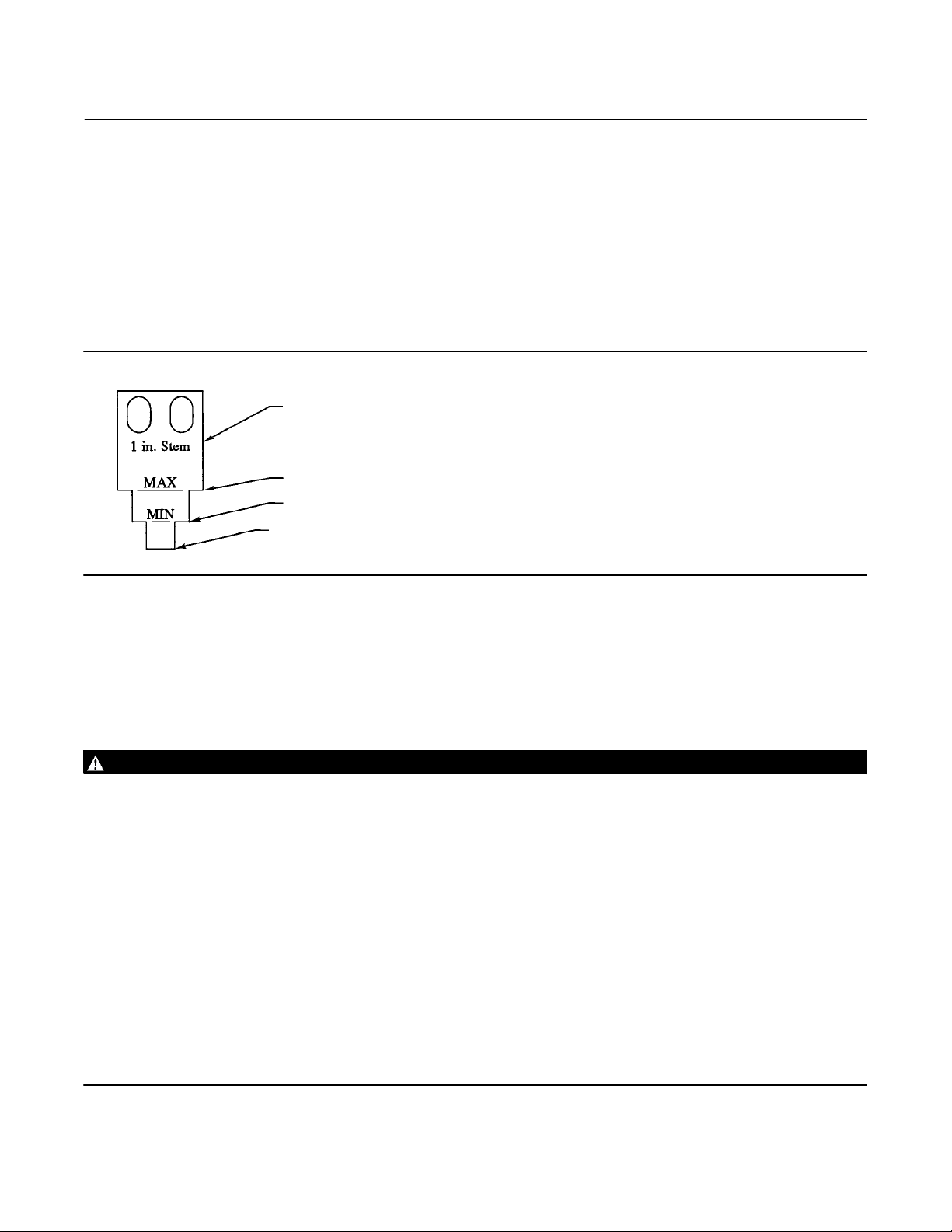
Figure 3. HIGH‐SEAL ULF Packing Assembly Showing the Load Properly Adjusted for Decompressed Springs
FLANGE
BELLEVILLE SPRINGS NOT COMPRESSED
INDICATOR DISK
INDICATOR DISK ALIGNED WITH BOTTOM OF LOAD SCALE
A4991‐2
THESE TWO SURFACES MUST REMAIN PARALLEL AS YOU ALTERNATELY AND EVENLY TIGHTEN THE PACKING NUTS.
The valve stem condition is critical to packing sealing performance and life. As‐new surface finish (0.1 μm [4 μin]R
a
max) is recommended for best performance. Refer to the appropriate valve instruction manual for instructions on
replacing the valve stem.
Check the condition of the packing bore after you have removed the packing. An easy method for cleaning debris and
minor imperfections from the bore is to use a brake cylinder hone attached to an electric drill. This method will do a
good job of cleaning the packing bore without changing the dimension of the bore.
Inspect the packing bore size and surface finish. If the packing bore is worn, pitted, damaged, or oversized more than
0.010 inch, replace the valve bonnet or have your Emerson Automation Solutions Service Center repair it.
Key number locations are shown in figure 6.
1. If a retrofit kit is being installed in place of the original packing, remove existing packing studs from the valve, and
replace them with the longer studs (key 200).
2. Install the packing arrangement into the valve packing box.
Note
Be sure to install the packing rings in the sequence shown in figure 6. Identify parts by color or by the number stamped on the part.
4
 Loading...