


Instruction Manual
D104413X012
Yarway Series 4300 TempLow
January 2019
Service Instructions for Yarway™ Series 43000
™
TempLow
Steam Desuperheater
This instruction manual was prepared by Emerson.
Do not install, operate or maintain this product
without being fully trained and qualified in valve,
actuator and accessory installation, operation and
maintenance.
To avoid personal injury or property damage it is
important to carefully read, understand, and follow all
of the contents of this manual, including all safety
cautions and warnings.
If you have any questions about these instructions,
contact your Emerson sales office
before proceeding.
Installation
WARNING
Always wear protective gloves, clothing, and eyewear when performing any installation operations. Check with your
process or safety engineer for any other hazards that may be present from exposure to process media.
Personal injury or equipment damage caused by sudden release of pressure may result if the desuperheater is installed
where service conditions could exceed the limits given on the product nameplate. To avoid such injury or damage, provide
a relief valve for over‐pressure protection as required by government or accepted industry codes and good engineering
practices.
CAUTION
When ordered, the desuperheater configuration and construction materials were specified to meet particular pressure,
temperature, pressure drop, and fluid conditions. Do not apply any other conditions to the desuperheater without first
contacting your Emerson sales office.
www.Fisher.com
Yarway Series 4300 TempLow
January 2019
Instruction Manual
D104413X012
Maintenance
WARNING
Avoid personal injury or property damage from sudden release of process pressure or bursting of parts. Before performing
any maintenance operations:
D Do not remove the actuator from the valve while the valve is still pressurized.
D Always wear protective gloves, clothing, and eyewear when performing any maintenance operations.
D Disconnect any operating lines providing air pressure, electric power, or a control signal to the actuator. Be sure the
actuator cannot suddenly open or close the valve.
D Use bypass valves or completely shut off the process to isolate the valve from process pressure. Relieve process pressure
from both sides of the valve. Drain the process media from both sides of the valve.
D Safely vent the power actuator loading pressure.
D Use lock-out procedures to be sure the above measures stay in effect with you work on the equipment.
D The valve packing box may contain process fluids that are pressurized, even with the valve has been removed from the
pipeline. Process fluids may spray out under pressure when removing the packing hardware or packing rings.
D Check with your process or safety engineer for any other hazards that may be present from exposure to process media.
CAUTION
When adjusting the travel stop for the closed position of the valve ball or disk, refer to the appropriate valve instruction
manual for detailed procedures. Undertravel or overtravel at the closed position may result in poor valve performance
and/or damage to the equipment .
Neither Emerson, Emerson Automation Solutions, nor any of their affiliated entities assumes responsibility for the selection, use or maintenance
of any product. Responsibility for proper selection, use, and maintenance of any product remains solely with the purchaser and end user.
Yarway and Templow are marks owned by one of the companies in the Emerson Automation Solutions business unit of Emerson Electric Co. Emerson
Automation Solutions, Emerson, and the Emerson logo are trademarks and service marks of Emerson Electric Co. All other marks are the property of their
respective owners.
The contents of this publication are presented for informational purposes only, and while every effort has been made to ensure their accuracy, they are not
to be construed as warranties or guarantees, express or implied, regarding the products or services described herein or their use or applicability. All sales are
governed by our terms and conditions, which are available upon request. We reserve the right to modify or improve the designs or specifications of such
products at any time without notice.
Emerson Automation Solutions
Marshalltown, Iowa 50158 USA
Sorocaba, 18087 Brazil
Cernay, 68700 France
Dubai, United Arab Emirates
Singapore 128461 Singapore
www.Fisher.com
2
E 2019 Fisher Controls International LLC. All rights reserved.
YARWAY TEMPLOW® STEAM DESUPERHEATER
InstallatIon and MaIntenance InstructIons
Before installation these instructions must be fully read and understood
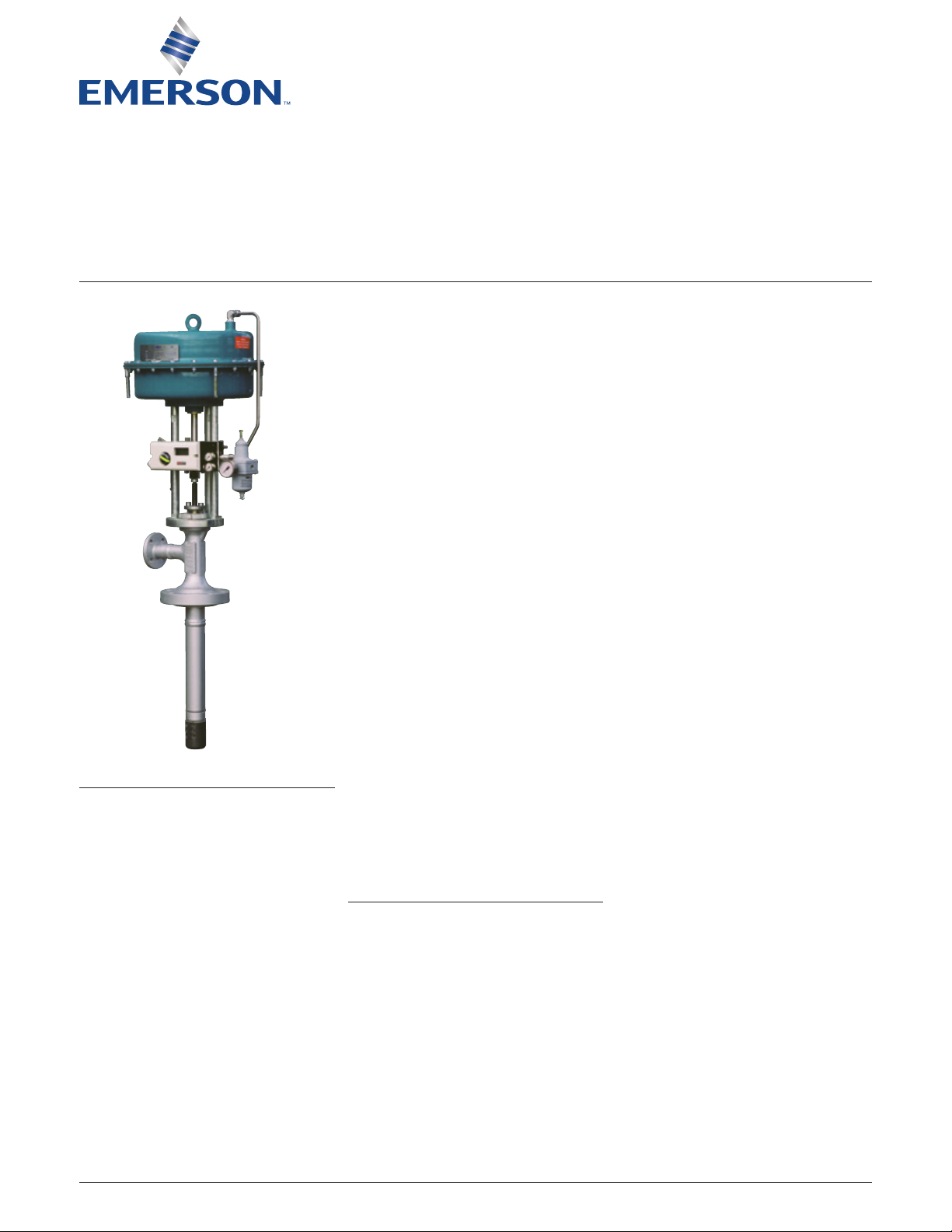
PRINCIPLES OF OPERATION
The Yarway TempLow Desuperheater (also
model 91 and 93) responds to pneumatic or
electric signals generated by a temperature
instrumentation control loop to provide
automatic introduction and metering of
cooling water for steam temperature control.
This desuperheating process effectively
and efficiently cools steam in accordance
to a thermodynamic heat balance at
constantpressure.
Desuperheating water, at a pressure at least
50 psi above steam pressure, enters the
valve at a flanged inlet. Water flows down
through the jacket to the seating area above
the disc where tight shutoff is achieved.
Whenthetemperaturecontrol unit signals for a
reduction in steam temperature, the pneumatic
actuator moves the stem/disc downward,
progressively uncovering a series ofvortex
feedholes. The water enters the vortex,
acquires a rotational sense and exits the spray
nozzle as a thin spinning conical fan which
immediately breaks up into a finely atomized
mist of water droplets. These mix with the
superheated steam for rapid evaporation.
There are seven stages of water control for
each vortex nozzle. Multiple nozzles are fitted
to the spray cylinder, thus giving a fine control
capability and fast response to a change
in the temperature control signal. Use of
multiple swirl chamber, orifice fan type spray
nozzles provide the sequential application
of an efficiently generated spray cone. The
combination provides a precise method of
control with a high order of rangeability. In the
normally closed position, the desuperheater
maintains a tight shutoff by virtue of the
actuator top works.
Valve selection is based on flow requirement
at maximum conditions of water need and
nominal water pressure. The valve exhibits
a linear or modified linear characteristic.
Nominal flow should be in the range
of50% to 80% of maximum valve capacity.
Follow the Yarway certified engineering
drawing for specific details which supersede
these general instructions. If the conditions
differ from those specified, consult the Yarway
Customer Services Department.
STANDARD SPECIFICATIONS
• Steam pressure and temperature ratings Standard Class Valve ASME B16.34 - limits
as specified for ASTM-A217-WC6 in Pressure
Classes 150, 300, 600, 900 and 1500.
• Steam line installation diameters
(minimum)- nozzle sizes A6 and B6 - 6inch
diameter minimum, C6, D6, and E6 - 8inch
diameter minimum. Consult certified
drawing.
• Cooling water supply pressure - water
pressure 50 psi greater than steam
pressureas measured at the valve inlet.
• Steam line nozzle and valve outlet flange3inch ASME B16.5 (DN 80) raised face pressure class as specified.
Extension pipe 3 inch schedule 160 maximum
(2.6 inch diameter clearance).
• Valve water inlet flange - 1 inch (DN 25)
ASMEB16.5 raised face flange; pressure
class or DIN flange as specified.
• Valve actuator/positioner - standard
actuator; Yarway Model 20, air failure to
close diaphragm type. Positioner upon
clientrequest.
• Instrument air failure mode - loss of
instrument air, valve fails closed.
• Instrument electric signal: 4-20 mA.
• Instrument air signal - standard - 3 to 15 psig
(.21 to 1.03 bar).
• Connections - ¼ inch - NPT instrument air
supply (IA) and PG 20 instrument signal (IS).
Check certified order drawing for
specificdetails.
Emerson.com/FinalControl
© 2017 Emerson. All rights reserved.
Engineering Doc. #961245 Rev. H
VCIOM-03325-US 15/04

YARWAY TEMPLOW® STEAM DESUPERHEATER
InstallatIon and MaIntenance InstructIons
UNPACKING, PREPARATION AND STORAGE
Upon receipt of the valve, inspect valve and
shipping container for transit damage such as
a broken crate, broken yoke, bent valve stem or
broken accessories. Check the documentation,
identification plate, valve tag data, instruction
manual, etc. Locate and identify spare parts
included in the shipment.
Use the shipping container for temporary
valve protection. Leave protective covers in
place until ready to proceed with inspection
and installation. Store the valve in a clean, dry
location. If outdoor storage is unavoidable,
support the valve off the ground or pavement
and provide a waterproof covering. Lift the valve
by means of straps around valve body and inlet
flange. Do not use the actuator yoke to attach
lifting straps.
LONG TERM STORAGE
Use a dry, heated, inside storage area. Remove
the valve stem packing. Make sure valve is dry
and free from moisture. Apply Cosmoline-type
protective grease to the flange face, packing
stuffing box and valve stem.
PREPARATION FOR INSTALLATION
Remove all paper, tape and packing materials,
and all foreign materials. Transport carefully
to the installation site. Remove valve protective
covers and install the valve in the system.
INSTALLATION
See Yarway Engineering Approval Drawings
forcertified dimensions, installation details
andmarking for each TempLow Desuperheater
by serial no./tag no.
Main steam system piping (Figures 1 and 2)
1. The desuperheater requires a minimum
of 15 feet (4.6 meters) of straight pipe
from the valve installation to the first
bend downstream and six straight pipe
diametersupstream.
2. Branching of the main steam pipe should
not be allowed between the desuperheater
and the temperature sensor.
3. Pipe bends should be long radius type to aid
keeping the steam/water vapor mixture in
suspension until evaporated.
4. Avoid using “T” fittings between the
desuperheater and the temperature sensor.
5. The distance from the desuperheater
to the temperature sensor is nominally
40feet (12.2 meters). The certified drawing
specifies a minimum based on system
requirements. Greater distance assures
full mixing and total evaporation at low
steamvelocities.
Care must be exercised to accommodate
low steam flow conditions near saturation
temperature. A water film can form on the
pipe wall and reach the temperature sensor.
6. The temperature sensor should be mounted
in accordance with manufacturer’s
recommendation. Yarway recommends
mounting in the top of the line ± 45°.
The sensor should not be mounted at the
outside of an elbow.
7. The steam velocity can be increased by
reducing the steam pipe size by one or
two sizes for the distance between the
desuperheater and the sensor.
8. Desuperheater applications requiring
control over large turn down load ranges
can utilize split range control from a
single sensor for multiple desuperheaters
installed in the steam pipe.
9. Steam dump systems may require multiple
units to control maximum temperature.
Pipe mounting orientation
1. The desuperheater may be mounted at90°
to the steam line for all orientations of
steam flow.
2. The “vertical-up” position is preferred for
the valve stem and actuator. If the TempLow
is installed in other than vertical position,
consideration must be given to supporting
the actuator.
3. The cooling water supply should be clean,
filtered condensate or boiler feed water.
The source selection must consider water
temperature.
4. Yarway recommends that the cooling water
line include a locked open shut-off valve
and a strainer with 0.004 inch (0.1mm)
perforated mesh sized for the flow
requirements. The cooling water line must
be thoroughly flushed prior to connection
for use.
5. The water line pressure at the inlet to
the valve is to be per certified drawing
datasheet.
STEAM LINE
Mounting flange and pipe (Figure 3)
1. The spray cylinder should be located at
the center line of the pipe which is most
important in small lines.
2. The primary dimension variable is the
length “X” of the 3-inch (DN 80) nozzle that
supports the mounting flange. The 3-inch
(DN 80) connecting pipe must provide
a 2.60-inch (65 mm) diameter internal
clearance. A 3-inch schedule 160 pipe
provides the maximum wall thickness
pipeallowed.
3. The variable “X” is nominally calculated by
subtracting ½ the pipe OD dimension from
15½ inches (394 mm). This dimension varies
in order that the spray cylinder portion of the
valve is centered within the pipe OD(“Y”).
For pipe sizes greater than 24inches
(600 mm) the “X” dimension is 3½inches
(88.9mm). (See certified drawing.)
2
YARWAY TEMPLOW® STEAM DESUPERHEATER
InstallatIon and MaIntenance InstructIons
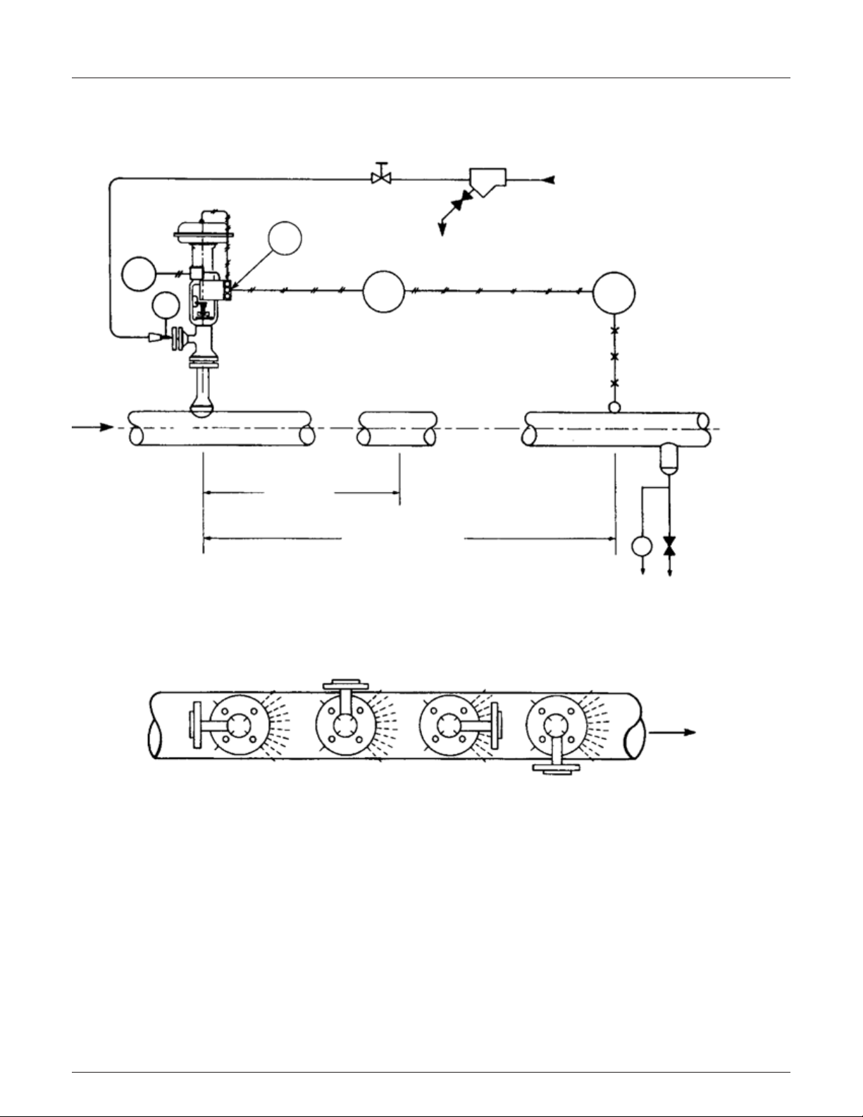
RECOMMENDED STANDARD INSTALLATION
DESUPERHEATING STATION
FIGURE 1
Lock open
Strainer
Water
Steam flow
IS
Blow down
IA
TTTIC
PI
Boot locate
at low point
15 ft. minimum
straight pipe
downstream
40 ft. minimum
distance to sensor
Spray nozzles must be oriented to direct spray with thedirection of flowing steam. No deviation allowed.
Important
T
Blow down
Dirt leg
FIGURE 2
Configuration position
Water inlet orientation
Steam flow
1 2 3 4
3
 Loading...