

Fisher Instruction Manual: Fisher Vee-Ball V200U Rotary Control Valve DN80 through 250 (NPS 3 through 10) Manuals & Guides
Instruction Manual
D104548X012
V200U Valve
Fisher™ Vee‐Ball™ V200U Rotary Control Valve
DN 80 through 250 (NPS 3 through 10)
May 2020
Contents
Introduction 1.................................
Scope of Manual 1.............................
Description 2.................................
Specifications 2...............................
Educational Services 2
Installation 3....................................
Maintenance 7..................................
Packing Maintenance 7.........................
Replacing the HD Ball Seal 11....................
Bearing and Ball Maintenance 14.................
Actuator Mounting 19
Determining Mounting Position 20...............
Determining Closed Position 20.................
Parts Ordering 23
Parts Kits 23.....................................
Parts List 24.....................................
................................
..........................
............................
Figure 1. Fisher V200U Flangeless Vee‐Ball with
™
Bettis
RPE Actuator and FIELDVUE™ DVC2000
Digital Valve Controller
X1711
Introduction
Scope of Manual
This instruction manual provides installation, operation, maintenance, and parts information for
the Fisher Vee‐Ball Flangeless V200U rotary control valve sizes DN80 through DN250
(NPS 3 through NPS 10) (see figure 1).
For information on ENVIRO‐SEAL
(D101643X012
www.Fisher.com
). Refer to separate manuals for information concerning the actuator, positioner and accessories.
Do not install, operate, or maintain Vee-Ball valves without being fully trained and qualified in valve,
actuator, and accessory installation, operation, and maintenance. To avoid personal injury or property
damage, it is important to carefully read, understand, and follow all the contents of this manual,
including all safety cautions and warnings. If you have any questions about these instructions, contact
your Emerson sales office
™
packing, see the ENVIRO‐SEAL Packing System for Rotary Valves instruction manual
before proceeding.

V200U Valve
May 2020
Table 1. Specifications
Instruction Manual
D104548X012
Valve Sizes
See table 2
Valve End Connection Styles
Flangeless (all sizes) J mates EN1092-1 PN10-40
Type B raised-face flanges (see table 2) J mates with
ASME B16.5 CL150/CL300 raised-face flanges (see
table 2)
Maximum Inlet Pressure
Consistent with applicable EN 12516-1 or
ASME B16.34 ratings
Standard Flow Direction
Forward (into the convex face of the Vee‐Ball)
Dimensions
See table 4
Actuator Mounting
J Right‐hand, standard or J left‐hand, optional, as
viewed from the valve inlet (see figure 10 and the
Actuator Mounting section)
1. The pressure/temperature limits in this manual, and any applicable code or standard limitation, should not be exceeded.
(1)
Standard: Ball rotates counterclockwise to close
when viewed from actuator side of valve
Optional: Ball rotates clockwise to close
Ball rotation is 90 degrees
Valve/Actuator Action
For right-hand mount actuator, the standard ball
design and actuator action is counter-clockwise to
close (CCW). The ball will rotate to the top of the
valve body when open for a horizontal pipe run with
the valve shaft positioned horizontal. J Left-hand
actuator mounting with CCW action is an option.
Left-hand actuator mounting with a special clockwise
to close (CW) ball design and actuator action is also
available to allow the ball to rotate to the top of the
valve body for a horizontal pipe run with the valve
shaft positioned horizontal.
With diaphragm or piston rotary actuator,
field‐reversible between:J push‐down‐to‐close
(PDTC) (extending actuator rod closes valve) and
J push‐down‐to‐open (PDTO) (extending actuator
rod opens valve.)
Approximate Weight
See table 3
Description
The V200U Vee‐Ball valves (figure 1) with a V‐notch ball are used in throttling or on-off service. The V200U is a
flangeless construction capable of interfacing with EN 1092-1 Type B or ASME B16.5 raised face flanges. The splined or
square drive shaft connects to a variety of rotary‐shaft actuator options.
Specifications
Specifications for these valves are shown in table 1 and in the Fisher V200U Vee-Ball Rotary Control Valves Bulletin
51.3:V200U (D104550X012).
Educational Services
For information on available courses for Fisher Vee-Ball valves, as well as a variety of other products, contact:
Emerson Automation Solutions
Educational Services - Registration
Phone: 1-641-754-3771 or 1-800-338-8158
E-mail: education@emerson.com
emerson.com/fishervalvetraining
2
Instruction Manual
D104548X012
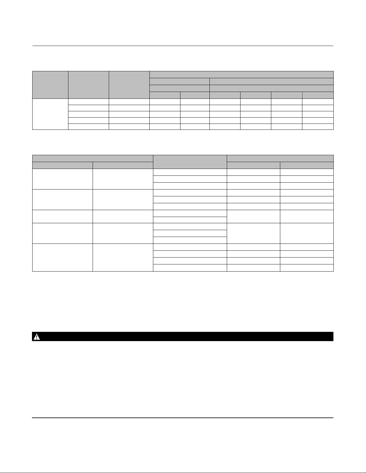
Table 2. Valve Body Materials, End Connections, and Ratings
VALVE BODY
MATERIAL
EN 1.4408/CF8M
VALVE SIZE, DN VALVE SIZE, NPS
80 3 X X X X X X
100 4 X X X X X X
150 6 X X X X X X
200 8 X X X X X X
250 10 X X X X X X
Table 3. V200U Approximate Weights
VALVE SIZE
DN NPS kg lbs
80 3
100 4
150 6
200 8
250 10
ASME B16.5 EN1092-1
Raised Face Flange Type B Raised Face Flange
CL150 CL300 PN10 PN16 PN25 PN40
PN10-40 9 19
CL150 and 300 13 28
PN10/16 12 26
PN25/40 13 28
CL150 and 300
PN10-40
CL150 and 300
PN10/16
PN25/40
PN10/16 64 140
PN25/40 71 156
V200U Valve
FLANGELESS VALVE END CONNECTION COMPATIBILITY
RATING
CL150 8 18
CL300 10 22
27 58
49 109
CL150 64 140
CL300 102 225
WEIGHT
May 2020
Installation
Installation steps are provided in this section for V200U valves. Key numbers in installation procedures are shown in
figure 14 and 15 unless otherwise indicated.
WARNING
Always wear protective gloves, clothing, and eyewear when performing any installation operations to avoid personal
injury.
Personal injury or equipment damage caused by sudden release of pressure may result if the valve assembly is installed
where service conditions could exceed either the valve body rating or the mating pipe flange joint rating. To avoid such
injury or damage, provide a relief valve for overpressure protection as required by government or accepted industry codes
and good engineering practices.
Check with your process or safety engineer for any additional measures that must be taken to protect against process
media.
If installing into an existing application, also refer to the WARNING at the beginning of the Maintenance section in this
instruction manual.
3

V200U Valve
May 2020
Instruction Manual
D104548X012
WARNING
When ordered, the valve configuration and construction materials were selected to meet particular pressure, temperature,
pressure drop, and controlled fluid conditions. Responsibility for the safety of process media and compatibility of valve
materials with process media rests solely with the purchaser and end‐user. To avoid possible personal injury and because
some valve/trim material combinations are limited in their pressure drop and temperature ranges, do not apply any other
conditions to the valve without first contacting your Emerson sales office
.
WARNING
The valve drive shaft is not necessarily grounded to the pipeline when installed. Personal injury or property damage could
result from an explosion caused by a discharge of static electricity from valve components if the process fluid or the
atmosphere around the valve is flammable. If the atmosphere around the valve or the process fluid is flammable,
electrically bond the drive shaft to the valve.
Note
Standard PTFE packing is composed of a partially conductive carbon‐filled PTFE female adaptor with PTFE V‐ring packing. Standard
graphite packing is composed of all conductive graphite ribbon packing. Alternate shaft‐to‐valve body bonding is available for
hazardous service areas where the standard packing is not sufficient to bond the shaft to the valve (see the following step).
Attach the optional bonding strap assembly (key 131, figure 2) to the valve drive shaft (key 6) with the clamp (key 130,
figure 2) and connect the other end of the bonding strap assembly to the valve body with the cap screw (key 23).
1. If the valve is to be stored before installation, protect the flange mating surfaces and keep the valve body cavity dry
and free of foreign material.
2. Install a three‐valve bypass around the control valve assembly if continuous operation will be necessary during
inspection and maintenance of the valve.
3. The valve is normally shipped as part of a control valve assembly, with an actuator mounted on the valve. If the
valve and actuator have been purchased separately or if the actuator has been removed, mount the actuator
according to the Actuator Mounting section and the appropriate actuator instruction manual.
4. Standard flow direction is forward (fluid flows into the convex face of the V-notch ball).
5. Install the valve in a horizontal or vertical pipeline with the drive shaft in a horizontal position.
CAUTION
Do not allow the valve to be installed in the pipeline with the drive shaft in the vertical position because of excessive wear
to valve component parts.
6. The actuator can be right‐ or left‐hand mounted with the shaft in a horizontal orientation as shown in figure 1. If
necessary, refer to the appropriate actuator instruction manual for actuator installation and adjustment
procedures.
CAUTION
Ensure the valve and adjacent pipelines are free of foreign material that could damage the valve seating surfaces.
4

Instruction Manual
D104548X012
V200U Valve
May 2020
7. Be certain the valve and adjacent pipelines are free of any foreign material that could damage the valve sealing
surfaces.
8. Be sure the pipeline flanges are in line with each other.
Figure 2. Optional Shaft‐to‐Body Bonding Strap Assembly
ACTUATOR
A
A
37A6528‐A
A3143‐2
VALVE
BODY
VIEW A‐A
Installing V200U Valves
1. To avoid potential interference with the valve outlet end pipe flange, the V200U ball should be in the closed
position prior to installation. Install the V200U valve using long studs to connect the two pipeline flanges. Refer to
figure 3 for the length of studs required based on the mating pipeline flange pressure class. Lubricate the studs with
anti‐seize lubricant.
CAUTION
For DN 100, 200, and 250 (NPS 4, 8, and 10), damage to the ball (key 2) could occur if the downstream piping interferes
with the ball rotation. Prior to installing the valve body between adjacent flanges, reference dimension P in table 4 and
measure carefully to ensure the ball will rotate without interference.
2. Install two studs in the flanges before you place the valve in the line. Place the two studs so they will contact the
line‐centering features at the bottom of the valve body.
3. Insert appropriate flange gaskets that are compatible with the process fluid.
4. Place the valve on the two studs. Install all remaining studs. Measure carefully to be sure the valve is centered on the
pipeline flanges, and tighten the flange stud nuts. Tighten the nuts in a criss‐cross sequence to be sure the flange
gaskets are properly torqued.
5. Connect pressure lines to the actuator as indicated in the actuator instruction manual. When an auxiliary manual
actuator is used with a power actuator, install a bypass valve on the power actuator (if one is not supplied) for use
during manual operation.
WARNING
Personal injury could result from packing leakage. Valve packing was tightened before shipment; however the packing
might require some readjustment to meet specific service conditions. Check with your process or safety engineer for any
additional measures that must be taken to protect against process media.
5
V200U Valve
(1)P(2)
(3)
(3)
May 2020
Instruction Manual
D104548X012
If the valve has ENVIRO‐SEAL live‐loaded packing installed, this initial re‐adjustment will probably not be required. See
ENVIRO‐SEAL Packing System for Rotary Valves instruction manual (D101643X012
) for packing instructions.
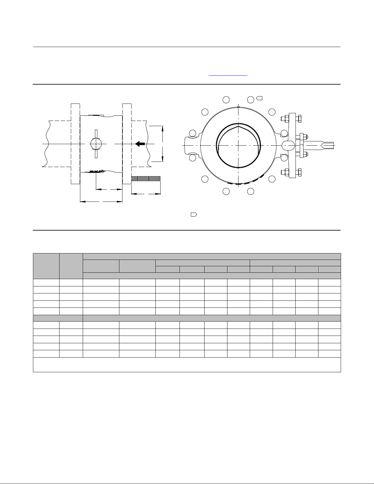
Figure 3. Fisher V200U Dimensions and Required Clearances for Installation
1
P
GG69033-A
B
A
M
GG69042
NOTE:
1
STUD QUANTITY AND PLACEMENT SHOWN FOR EXAMPLE DN200 PN40 FLANGE.
Table 4. Fisher V200U Dimensions and Required Clearances for Installation
VALVE
SIZE,
DN
VALVE
SIZE,
NPS
A B
PN 10/16 PN 25/40 CL150 CL300 PN 10/16 PN 25/40 CL150 CL300
80 3 100 59 225 240 204 216 - - - - - - - - - - - -
100 4 116 68 250 270 223 242 103 104 99 99
150 6 160 89 310 340 274 299 - - - - - - - - - - - -
200 8 200 124 355 405 324 356 188 190 188 188
250 10 240 147 410 470 375 413
80 3 3.94 2.34 8.86 9.45 8.00 8.50 - - - - - - - - - - - -
100 4 4.58 2.67 9.85 10.63 8.75 9.50 4.06 4.09 3.90 3.90
150 6 6.30 3.52 12.21 13.39 10.75 11.75 - - - - - - - - - - - -
200 8 7.87 4.89 13.98 15.95 12.75 14.00 7.40 7.48 7.40 7.40
250 10 9.45 5.78 16.15 18.51 14.75 16.25
1. Clearance necessary to remove the bolt.
2. Minimum internal diameter of the mating pipe or flange required for Vee-Ball clearance.
3. The NPS 10 CL300 construction requires 4 bolts per side (8 total) to be installed in blind, tapped holes on the valve body. The M value for these 1 – 8 UNC fasteners is 140 mm (5.5 inch).
DIMENSION
M
mm
253 253 242 237
Inches
9.96 9.96 9.53 9.33
6

Instruction Manual
D104548X012
V200U Valve
May 2020
Maintenance
Valve parts are subject to normal wear and must be inspected and replaced as necessary. The frequency of inspection
and replacement depends upon the severity of service conditions.
Key numbers in this procedure are shown in figures 14 and 15 unless otherwise noted.
WARNING
The Vee‐Ball closes with a shearing, cutting motion, which could result in personal injury. To avoid injury, keep hands,
tools, and other objects away from the Vee‐Ball while stroking the valve.
Avoid personal injury from sudden release of process pressure. Before performing any maintenance operations:
D Do not remove the actuator from the valve while the valve is still pressurized.
D Disconnect any operating lines providing air pressure, electric power, or a control signal to the actuator. Be sure the
actuator cannot suddenly open or close the valve.
D Use bypass valves or completely shut off the process to isolate the valve from process pressure. Relieve process pressure
from both sides of the valve. Drain the process media from both sides of the valve.
D Vent the power actuator loading pressure and relieve any actuator spring precompression.
D Use lock‐out procedures to be sure that the above measures stay in effect while you work on the equipment.
D Always wear protective gloves, clothing, and eyewear when performing any maintenance operations.
D The valve packing area may contain process fluids that are pressurized, even when the valve has been removed from the
pipeline. Process fluids may spray out under pressure when removing the packing hardware or packing rings.
D Check with your process or safety engineer for any additional measures that must be taken to protect against process
media.
Packing Maintenance
Key numbers in this procedure are shown in figures 14 and 15 unless otherwise noted. A detailed view of the packing is
also shown in figure 4.
If the valve is equipped with the ENVIRO‐SEAL Packing System, refer to:
D The separate ENVIRO‐SEAL Packing System for Rotary Valves instruction manual (D101643X012
instructions, and
D The Parts List section of this manual for retrofit kits, parts kits, and individual parts.
If the packing is relatively new and tight on the drive shaft (key 6), and if tightening the packing follower nuts does not
stop leakage, it is possible that the drive shaft is worn or nicked so that a seal cannot be made. If the leakage comes
from the outside diameter of the packing, it is possible that the leakage is caused by nicks or scratches on the packing
box wall. Inspect the drive shaft and packing box wall for nicks or scratches while performing the following procedure.
Replacing Packing
When using this procedure, it is recommended that the actuator not be removed from the valve while the valve is still
in the pipeline or between flanges. Valve/actuator adjustments must be made with the valve out of the pipeline. Refer
to the Determining Closed Position portion of the Actuator Mounting section.
) for maintenance
7
V200U Valve
May 2020
Instruction Manual
D104548X012
Disassembly
WARNING
Observe the steps in the WARNING at the beginning of the Maintenance section.
1. Isolate the control valve from the line pressure, release pressure from both sides of the valve body, and drain the
process media from both sides of the valve. If using a power actuator, shut off all pressure lines to the power
actuator, release pressure from the actuator, and disconnect the pressure lines from the actuator. Use lock‐out
procedures to be sure that the above measures stay in effect while you are working on the equipment.
2. To avoid potential interference with the valve outlet end pipe flange, the V200U ball should be in the closed
position prior to removal.
3. Remove line bolting, remove the control valve from the pipeline, and place the valve/actuator assembly on a flat
surface with the seal protector ring facing up.
4. Remove the actuator cover. Take note of the orientation of the actuator with respect to the valve body and the
lever orientation with respect to the valve drive shaft (see figure 12) for Fisher actuation.
WARNING
When the actuator is removed from the valve, the ball/shaft assembly may suddenly rotate, with a shearing, cutting
motion, which could result in personal injury. To avoid injury, carefully rotate the ball to a stable position at the bottom of
the valve body cavity. Make sure the ball will not rotate.
CAUTION
When removing the actuator from the valve, do not use a hammer or similar tool to drive the lever or actuator off the valve
shaft. Driving the lever or actuator off the valve shaft could damage the ball, seal, and valve.
If necessary, use a puller to remove the lever or actuator from the valve shaft. It is okay to tap the puller screw lightly to
loosen lever or actuator, but hitting the screw with excessive force could damage the ball, seal, and valve.
5. Remove the clamped lever (do not loosen the actuator turnbuckle adjustment), remove the actuator mounting
screws and nuts (keys 23 and 24), and remove the actuator. (If necessary, refer to the actuator instruction manual
for assistance.)
6. If applicable, remove the bonding strap assembly before attempting to remove the packing (see figure 2).
7. Remove the packing follower nuts and packing follower (keys 17 and 20). For alloy packing constructions, the
packing follower (key 17) and a separate packing flange (key 40) must be removed if present.
If the valve is equipped with the ENVIRO‐SEAL packing system, refer to the ENVIRO‐SEAL Packing System for Rotary
Valves instruction manual (D101643X012
) for disassembly.
WARNING
Personal injury could result from packing leakage. Do not scratch the drive shaft or packing box wall while removing
packing parts in the following procedure.
8

Instruction Manual
D104548X012
V200U Valve
May 2020
8. Remove the packing parts (see figure 4, keys 16, 17, 35, and 39 depending on construction) using a formed wire
hook with a sharp end. Pierce the rings with the sharp end of the hook in order to remove them. Do not scratch the
drive shaft or packing box wall; scratching these surfaces could cause leakage. Clean all accessible metal parts and
surfaces to remove particles that would prevent the packing from sealing.
Assembly
If the valve is equipped with the ENVIRO‐SEAL packing system, refer to the ENVIRO‐SEAL Packing System for Rotary
Valves instruction manual (D101643X012
1. To help ensure correct centering of the Vee‐Ball (key 2) on the seal (key 11), make sure the ball is closed while you
install or tighten new packing. Insert a screwdriver, pry bar, or similar tool between the lower ear of the ball and the
valve body. Use the pry to move the ball tightly against the bearing on the actuator side of the valve (see figure 5).
Keep the ball in that position until you have completed packing installation and adjustment.
2. Install the new packing parts using the parts sequence shown in figure 4. Install the packing follower (key 17).
3. Secure the packing follower with the packing follower nuts (key 20). Tighten the nuts far enough to stop leakage
under operating conditions.
Note
If the valve is equipped with a bonding strap assembly (figure 2), re‐install the assembly.
) for assembly.
4. Reconnect the actuator and lever in accordance with the orientations that were noted in step 3 of the disassembly
procedures. If necessary, use figure 10 to identify the correct index marks.
5. Refer to the appropriate actuator instruction manual to complete actuator assembly and adjustment.
6. When the control valve is in operation, check the packing follower for leakage and re-tighten the packing follower
nuts (key 20) as necessary.
9
 Loading...