

Fisher Instruction Manual: Fisher V150E Expanded Outlet Vee-Ball Control Valve Manuals & Guides

Instruction Manual
D103435X012
V150E Valve
July 2017
Fisher™ V150E Expanded Outlet Vee-Ball
Valve
Contents
Introduction 1.................................
Scope of Manual 1.............................
Description 1.................................
Specifications 2...............................
Installation 2
Maintenance 5..................................
Packing Maintenance 5.........................
Replacing the HD Ball Seal 7.....................
Bearing and Ball Maintenance 12.................
Actuator Mounting 15
Determining Mounting Position 16...............
Determining Closed Position 16.................
Parts Ordering 16
Parts Kits 21.....................................
Parts List 22.....................................
....................................
............................
................................
Figure 1. Fisher V150E Expanded Outlet Vee-Ball
Valve with 2052 Actuator and FIELDVUE™ DVC6200
Digital Valve Controller
W9915
™
Control
Introduction
Scope of Manual
This instruction manual provides installation, operation, maintenance, and parts information for the Fisher Vee‐Ball
V150E rotary control valve (see figure 1).
For information on ENVIRO‐SEAL™ packing, see the ENVIRO‐SEAL Packing System for Rotary Valves instruction
manual, D101643X012
accessories.
Do not install, operate, or maintain a V150E valve without being fully trained and qualified in valve, actuator, and
accessory installation, operation, and maintenance. To avoid personal injury or property damage, it is important to
carefully read, understand, and follow all the contents of this manual, including all safety cautions and warnings. If you
have any questions about these instructions, contact your Emerson sales office
proceeding.
Description
V150E Vee‐Ball valves (figure 1) with a V‐notch ball are used in throttling service. The V150E valve is a raised‐face
flanged construction. The splined valve shaft connects to a variety of Fisher rotary‐shaft actuators.
. Refer to separate manuals for information concerning the actuator, positioner and
or Local Business Partner before
www.Fisher.com

V150E Valve
July 2017
Table 1. Specifications
Instruction Manual
D103435X012
Valve Sizes and End Connection Styles
J 80x100, J 100x150, J 150x200, J 200x250,
DN
J 250x300 and NPS J 3x4, J 4x6, J 6x8, J 8x10,
J 10x12 flanged valves that mate with J PN 10/16,
J JIS 10K, or J CL150 raised-face flanges (see table
2)
Actuator Mounting
Standard valve construction is for right-hand
mounting, as viewed from upstream end of valve with
the shaft horizontal. Actuator can be mounted in any
of four quadrants. Left-hand actuator mounting is
available upon request
Dimensions
See table 6 for dimensions
Standard Flow Direction
Forward (into the convex face of the V-notch ball)
Valve/Actuator Action
With compact 2052 spring and diaphragm or Fisher
1061 piston rotary actuator, the valve is
field-reversible between PDTC or PDTO:
push-down-to-close (extending actuator rod closes
Maximum Ball Rotation
90 degrees
Orientation
Valve shaft must be horizontal when installed in a
horizontal or vertical pipeline
1. The pressure/temperature limits in this manual and any applicable standard or code limitation for valve should not be exceeded.
valve) and push-down-to-open (extending actuator
rod opens valve)
Approximate Weight
See table 6
Table 2. Valve Body Material, End Connections, and Ratings
VALVE DESIGN VALVE BODY MATERIAL VALVE SIZE FLANGE END CONNECTIONS
DN 80x100, 100x150, 150x200,
V150E CG8M
200x250, 250x300
NPS 3x4, 4x6, 6x8, 8x10, 10x12
Compatible with PN 10/16 or
JIS 10K raised-face flanges
Compatible with CL150
raised-face flanges
Specifications
Specifications for these valves are shown in table 1 and in bulletin 51.3:V150E, V150E Expanded Outlet Vee-Ball
Control Valve (D103429X012
).
Installation
Installation steps are provided in this section for V150E valves. Key numbers in installation procedures are shown in
figure 10 unless otherwise indicated.
WARNING
Always wear protective gloves, clothing, and eyewear when performing any installation operations to avoid personal
injury.
Personal injury or equipment damage caused by sudden release of pressure may result if the valve assembly is installed
where service conditions could exceed either the valve body rating or the mating pipe flange joint rating. To avoid such
injury or damage, provide a relief valve for overpressure protection as required by government or accepted industry codes
and good engineering practices.
2

Instruction Manual
D103435X012
Check with your process or safety engineer for any additional measures that must be taken to protect against process
media.
If installing into an existing application, also refer to the WARNING at the beginning of the Maintenance section in this
instruction manual.
V150E Valve
July 2017
WARNING
When ordered, the valve configuration and construction materials were selected to meet particular pressure, temperature,
pressure drop, and controlled fluid conditions. Responsibility for the safety of process media and compatibility of valve
materials with process media rests solely with the purchaser and end‐user. To avoid possible personal injury and because
some valve/trim material combinations are limited in their pressure drop and temperature ranges, do not apply any other
conditions to the valve without first contacting your Emerson sales office
or Local Business Partner.
WARNING
The valve drive shaft is not necessarily grounded to the pipeline when installed. Personal injury or property damage could
result from an explosion caused by a discharge of static electricity from valve components if the process fluid or the
atmosphere around the valve is flammable. If the atmosphere around the valve or the process fluid is flammable,
electrically bond the drive shaft to the valve.
Note
Standard PTFE packing is composed of a partially conductive carbon‐filled PTFE female adaptor with PTFE V‐ring packing. Standard
graphite packing is composed of all conductive graphite ribbon packing. Alternate shaft‐to‐valve body bonding is available for
hazardous service areas where the standard packing is not sufficient to bond the shaft to the valve (see the following step).
Attach the optional bonding strap assembly (key 131, figure 2) to the valve drive shaft (key 6) with the clamp (key 130,
figure 2) and connect the other end of the bonding strap assembly to the valve body with the cap screw (key 23).
1. If the valve is to be stored before installation, protect the flange mating surfaces and keep the valve body cavity dry
and free of foreign material.
2. Install a three‐valve bypass around the control valve assembly if continuous operation will be necessary during
inspection and maintenance of the valve.
3. The valve is normally shipped as part of a control valve assembly, with an actuator mounted on the valve. If the
valve and actuator have been purchased separately or if the actuator has been removed, mount the actuator
according to the Actuator Mounting section and the appropriate actuator instruction manual.
4. Standard flow direction is with the smaller diameter flange end facing upstream.
5. Install the valve in a horizontal or vertical pipeline with the drive shaft in a horizontal position.
CAUTION
Do not allow the valve to be installed in the pipeline with the drive shaft in the vertical position because of excessive wear
to valve component parts.
6. The actuator can be right‐ or left‐hand mounted with the shaft in a horizontal orientation as shown in figure 1. If
necessary, refer to the appropriate actuator instruction manual for actuator installation and adjustment
procedures.
3

V150E Valve
July 2017
Instruction Manual
D103435X012
CAUTION
Ensure the valve and adjacent pipelines are free of foreign material that could damage the valve seating surfaces.
7. Be certain the valve and adjacent pipelines are free of any foreign material that could damage the valve sealing
surfaces.
8. Be sure the pipeline flanges are in line with each other.
Figure 2. Optional Shaft‐to‐Body Bonding Strap Assembly
ACTUATOR
A
A
37A6528‐A
A3143‐2
VALVE
BODY
VIEW A‐A
Installing V150E Valves
1. Install the V150E valve using standard length flange studs and nuts, appropriate for the inlet and outlet ends of the
valve as dictated by the size and rating of the flange, to connect the valve flanges to the pipeline flanges.
2. Lubricate the studs with anti‐seize lubricant.
3. Insert flat‐sheet line flange gaskets (or spiral‐wound gaskets with compression‐controlling center rings) that are
compatible with the flowing media.
4. Connect pressure lines to the actuator as indicated in the actuator instruction manual. When an auxiliary manual
actuator is used with a power actuator, install a bypass valve on the power actuator (if one is not supplied) for use
during manual operation.
WARNING
Personal injury could result from packing leakage. Valve packing was tightened before shipment; however the packing
might require some readjustment to meet specific service conditions. Check with your process or safety engineer for any
additional measures that must be taken to protect against process media.
If the valve has ENVIRO‐SEAL live‐loaded packing installed, this initial re‐adjustment will probably not be required. See
ENVIRO‐SEAL Packing System for Rotary Valves instruction manual, D101643X012
4
, for packing instructions.

Instruction Manual
D103435X012
V150E Valve
July 2017
Maintenance
Valve parts are subject to normal wear and must be inspected and replaced as necessary. The frequency of inspection
and replacement depends upon the severity of service conditions.
Key numbers in this procedure are shown in figure 10, unless otherwise noted.
WARNING
The Vee‐ball closes with a shearing, cutting motion, which could result in personal injury. To avoid injury, keep hands,
tools, and other objects away from the Vee‐ball while stroking the valve.
Avoid personal injury from sudden release of process pressure. Before performing any maintenance operations:
D Do not remove the actuator from the valve while the valve is still pressurized.
D Disconnect any operating lines providing air pressure, electric power, or a control signal to the actuator. Be sure the
actuator cannot suddenly open or close the valve.
D Use bypass valves or completely shut off the process to isolate the valve from process pressure. Relieve process pressure
from both sides of the valve. Drain the process media from both sides of the valve.
D Vent the power actuator loading pressure and relieve any actuator spring precompression.
D Use lock‐out procedures to be sure that the above measures stay in effect while you work on the equipment.
D Always wear protective gloves, clothing, and eyewear when performing any maintenance operations.
D The valve packing area may contain process fluids that are pressurized, even when the valve has been removed from the
pipeline. Process fluids may spray out under pressure when removing the packing hardware or packing rings.
D Check with your process or safety engineer for any additional measures that must be taken to protect against process
media.
Packing Maintenance
Key numbers in this procedure are shown in figure 10, unless otherwise noted. A detailed view of the packing is also
shown in figure 3.
If the valve is equipped with the ENVIRO‐SEAL Packing System, refer to:
D the separate ENVIRO‐SEAL Packing System for Rotary Valves instruction manual, D101643X012
instructions, and
D the Parts List section of this manual for retrofit kits, parts kits, and individual parts.
If the packing is relatively new and tight on the drive shaft (key 6), and if tightening the packing follower nuts does not
stop leakage, it is possible that the drive shaft is worn or nicked so that a seal cannot be made. If the leakage comes
from the outside diameter of the packing, it is possible that the leakage is caused by nicks or scratches on the packing
box wall. Inspect the drive shaft and packing box wall for nicks or scratches while performing the following procedure.
Replacing Packing
When using this procedure, it is recommended that the actuator not be removed from the valve while the valve is still
in the pipeline or between flanges. Valve/actuator adjustments must be made with the valve out of the pipeline. Refer
to the Determining Closed Position portion of the Actuator Mounting section.
, for maintenance
5

V150E Valve
July 2017
Instruction Manual
D103435X012
Disassembly
WARNING
Observe the steps in the WARNING at the beginning of the Maintenance section.
1. Isolate the control valve from the line pressure, release pressure from both sides of the valve body, and drain the
process media from both sides of the valve. If using a power actuator, shut off all pressure lines to the power
actuator, release pressure from the actuator, and disconnect the pressure lines from the actuator. Use lock‐out
procedures to be sure that the above measures stay in effect while you are working on the equipment.
2. Remove line bolting, remove the control valve from the pipeline, and place the valve/actuator assembly on a flat
surface with the inlet facing up.
3. Remove the actuator cover. Take note of the orientation of the actuator with respect to the valve body and the
lever orientation with respect to the valve drive shaft (see figure 9).
WARNING
When the actuator is removed from the valve, the ball/shaft assembly may suddenly rotate, with a shearing, cutting
motion, which could result in personal injury. To avoid injury, carefully rotate the ball to a stable position after the actuator
is removed.
CAUTION
When removing the actuator from the valve, do not use a hammer or similar tool to drive the lever or actuator off the valve
shaft. Driving the lever or actuator off the valve shaft could damage the ball, seal, and valve.
If necessary, use a puller to remove the lever or actuator from the valve shaft. It is okay to tap the puller screw lightly to
loosen lever or actuator, but hitting the screw with excessive force could damage the ball, seal, and valve.
4. Loosen the clamped lever, remove the actuator mounting screws and nuts (keys 23 and 24), and remove the
actuator. (If necessary, refer to the actuator instruction manual for assistance.)
5. If applicable, remove the bonding strap assembly before attempting to remove the packing (see figure 2).
6. Remove the packing follower nuts and packing follower (keys 17 and 20). For alloy packing constructions, the
packing follower (key 17) and a separate packing flange (key 40) must be removed if present.
If the valve is equipped with the ENVIRO‐SEAL packing system, refer to the ENVIRO‐SEAL Packing System for Rotary
Valves instruction manual, D101643X012
, for disassembly.
WARNING
Personal injury could result from packing leakage. Do not scratch the drive shaft or packing box wall while removing
packing parts in the following procedure.
7. Remove the packing parts (see figure 3, keys 16, 17, 35, and 39 depending on construction) using a formed wire
hook with a sharp end. Pierce the rings with the sharp end of the hook in order to remove them. Do not scratch the
6

Instruction Manual
D103435X012
drive shaft or packing box wall; scratching these surfaces could cause leakage. Clean all accessible metal parts and
surfaces to remove particles that would prevent the packing from sealing.
V150E Valve
July 2017
Assembly
If the valve is equipped with the ENVIRO‐SEAL packing system, refer to the ENVIRO‐SEAL Packing System for Rotary
Valves instruction manual, D101643X012
1. To help ensure correct centering of the Vee‐ball (key 2) on the seal (key 11), make sure the ball is closed while you
install or tighten new packing. Insert a screwdriver, pry bar, or similar tool between the lower ear of the ball and the
valve body. Use the pry to move the ball tightly against the bearing on the actuator side of the valve (see figure 4).
Keep the ball in that position until you have completed packing installation and adjustment.
2. Install the new packing parts using the parts sequence shown in figure 3. Install the packing follower (key 17).
3. Secure the packing follower with the packing follower nuts (key 20). Tighten the nuts far enough to stop leakage
under operating conditions.
Note
If the valve is equipped with a bonding strap assembly (figure 2), re-install the assembly.
, for assembly.
4. Reconnect the actuator and lever in accordance with the orientations that were noted in step 3 of the disassembly
procedures. If necessary, use figure 9 to identify the correct index marks.
5. Refer to the appropriate actuator instruction manual to complete actuator assembly and adjustment.
6. When the control valve is in operation, check the packing follower for leakage and retighten the packing follower
nuts (key 20) as necessary.
Replacing the HD Ball Seal
Perform this procedure if the control valve is not shutting off properly or if seal inspection or replacement is necessary.
The valve / actuator assembly must be removed from the pipeline and the actuator must be removed from the valve to
replace the ball seal. Key numbers are shown in figure 13 unless otherwise indicated. Ball Seal assembly details (with
key numbers) are also shown in figure 5.
WARNING
Perform the steps in the WARNING at the beginning of the Maintenance section of this manual.
Removing the HD seal
1. Remove line bolting, remove the control valve from the pipeline, remove the actuator (as discussed in the packing
section), and place the valve body on a flat work surface.
a. For NPS 3x4 and 4x6 valves, the ball must be removed to access the seal. See the Bearing and Ball Maintenance
Disassembly section on page 12 in this manual. Then return to this procedure and continue with the next steps.
7
V150E Valve
July 2017
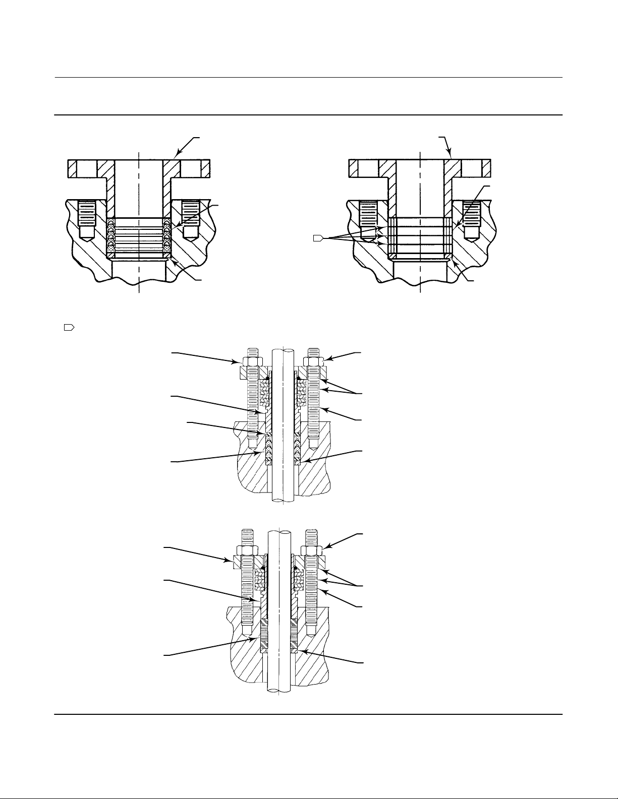
Figure 3. Packing Arrangements
PACKING FOLLOWER (KEY 17)
PACKING SET
(KEY 16)
Instruction Manual
D103435X012
PACKING FOLLOWER (KEY 17)
PACKING RING
(KEY 35)
1
PTFE V‐RING PACKING
NOTE:
1
GRAPHITE RIBBON PACKING ONLY.
28B5170
FOR V150E
INCLUDES ZINC WASHERS (KEY 36) FOR
PACKING FLANGE
(KEY 102)
SPRING PACK
ASSEMBLY
(KEY 103)
ANTI‐EXTRUSION
RING (KEY 106)
PACKING SET
(KEY 105)
PACKING FLANGE
(KEY 102)
SPRING PACK
ASSEMBLY
(KEY 103)
PACKING
BOX RING (KEY 39)
STANDARD PACKING
42B8445‐C
ENVIRO‐SEAL PTFE PACKING SYSTEM
PACKING
BOX RING (KEY 39)
GRAPHITE RIBBON PACKING
FOR V150E
PACKING FLANGE
NUT (KEY 101)
LUBRICANT
(KEY 113)
PACKING FLANGE
STUD (KEY 100)
PACKING BOX
RING (KEY 107)
PACKING FLANGE
NUT (KEY 101)
LUBRICANT
(KEY 113)
PACKING FLANGE
STUD (KEY 100)
PACKING SET
(KEY 105)
PACKING BOX
RING (KEY 107)
42B8445‐C
B2412‐1
ENVIRO‐SEAL GRAPHITE PACKING SYSTEM
8
 Loading...