


Instruction Manual
D100381X012
HS Valve
June 2019
Fisher™ HS Control Valve - OBS Valve
Contents
Introduction 1.................................
Safety Instructions 1............................
Specifications 2................................
Inspection and Maintenance Schedules 2...........
Parts Ordering 2................................
Installation 3..................................
Maintenance 4.................................
Latest Published Instruction Manual 5..............
Introduction
The product covered in this document is no longer in production. This document, which includes the latest published
version of the instruction manual, is made available to provide updates of newer safety procedures. Be sure to follow
the safety procedures in this supplement as well as the specific instructions in the included instruction manual.
Part numbers in the included instruction manual should not be relied on to order replacement parts. For replacement
parts, contact your Emerson sales office
For more than 20 years, Fisher products have been manufactured with asbestos‐free components. The included
manual might mention asbestos containing parts. Since 1988, any gasket or packing which may have contained some
asbestos, has been replaced by a suitable non‐asbestos material. Replacement parts in other materials are available
from your sales office.
.
Safety Instructions
Please read these safety warnings, cautions, and instructions carefully before using the product.
These instructions cannot cover every installation and situation. Do not install, operate, or maintain this product
without being fully trained and qualified in valve, actuator and accessory installation, operation and maintenance. To
avoid personal injury or property damage it is important to carefully read, understand, and follow all of the contents of
this manual, including all safety cautions and warnings. If you have any questions about these instructions, contact
your Emerson sales office before proceeding.
www.Fisher.com

HS Valve
June 2019
Instruction Manual
D100381X012
Specifications
This product was intended for a specific range of service conditions‐‐pressure, pressure drop, process and ambient
temperature, temperature variations, process fluid, and possibly other specifications. Do not expose the product to
service conditions or variables other than those for which the product was intended. If you are not sure what these
conditions or variables are, contact your Emerson sales office
other pertinent information that you have available.
for assistance. Provide the product serial number and all
Inspection and Maintenance Schedules
All products must be inspected periodically and maintained as needed. The schedule for inspection can only be
determined based on the severity of your service conditions. Your installation might also be subject to inspection
schedules set by applicable governmental codes and regulations, industry standards, company standards, or plant
standards.
In order to avoid increasing dust explosion risk, periodically clean dust deposits from all equipment.
When equipment is installed in a hazardous area location (potentially explosive atmosphere), prevent sparks by proper
tool selection and avoiding other types of impact energy. Control Valve surface temperature is dependent upon
process operating conditions.
WARNING
Control valve surface temperature is dependent upon process operating conditions. Personal injury or property damage,
caused by fire or explosion, can result if the valve body surface temperature exceeds the acceptable temperature for the
hazardous area classification. To avoid an increase of instrumentation and/or accessory surface temperature due to process
operating conditions, ensure adequate ventilation, shielding, or insulation of control valve components installed in a
potentially hazardous or explosive atmosphere.
Parts Ordering
Whenever ordering parts for older products, always specify the serial number of the product and provide all other
pertinent information that you can, such as product size, part material, age of the product, and general service
conditions. If you have modified the product since it was originally purchased, include that information with your
request.
WARNING
Use only genuine Fisher replacement parts. Components that are not supplied by Emerson Automation Solutions should
not, under any circumstances, be used in any Fisher product, because they may void your warranty, might adversely affect
the performance of the product, and could cause personal injury and property damage.
2

Instruction Manual
D100381X012
HS Valve
June 2019
Installation
WARNING
D Personal injury or equipment damage caused by sudden release of pressure or bursting of parts may result if the valve
assembly is installed where service conditions could exceed the limits given in the applicable product literature, the
limits on the appropriate nameplates, or the mating pipe flange rating. Use pressure‐relieving devices as required by
government or relevant industry codes and good engineering practices. If you cannot determine the ratings and limits
for this product, contact your Emerson sales office
D To avoid personal injury, always wear protective gloves, clothing, and eyewear when performing any installation
operations.
D To avoid personal injury or property damage, use proper lifting and rigging practices while lifting, installing or
removing the valve assembly. Be sure to use lifting and rigging equipment properly sized and selected for the weight
and configuration of the valve assembly or component being lifted.
D Personal injury could result from packing leakage. Valve packing was tightened before shipment; however, the packing
might require some readjustment to meet specific service conditions.
D Many rotary shaft valves are not necessarily grounded to the pipeline when installed in a flammable, hazardous, oxygen
service, or explosive atmospheres. An explosion is possible, due to the discharge of static electricity from the valve
components. To avoid personal injury or property damage, make sure that the valve is grounded to the pipeline before
placing the control valve assembly into service. Use and maintain alternate shaft‐to‐body bonding, such as a
shaft‐to‐body bonding strap assembly.
D Rotary shaft valves are designed and intended for installation between flanges. Personal injury or property damage may
result from improper installation. To avoid personal injury or property damage caused by the sudden release of
pressure or bursting of parts, do not use or install rotary shaft valves (including single lug constructions) for dead‐end
service.
D Check with your process or safety engineer for any additional measures that must be taken to protect against process
media.
D If installing into an existing application, also refer to the WARNING in the Maintenance section.
D When ordered, the valve configuration and construction materials were selected to meet particular pressure,
temperature, pressure drop, and controlled fluid conditions. Responsibility for the safety of process media and
compatibility of valve materials with process media rests solely with the purchaser and end‐user. To avoid possible
personal injury and because some valve/trim material combinations are limited in their pressure drop and temperature
ranges, do not apply any other conditions to the valve without first contacting your Emerson sales office.
before proceeding.
CAUTION
D Ensure that the valve and adjacent pipelines are free of foreign material that could damage the valve seating surfaces.
3

HS Valve
June 2019
Instruction Manual
D100381X012
Maintenance
WARNING
Avoid personal injury or property damage from sudden release of process pressure or bursting of parts. Before performing
any maintenance operations:
D Always wear protective gloves, clothing, and eyewear.
D Disconnect any operating lines providing air pressure, electric power, or a control signal to the actuator. Be sure the
actuator cannot suddenly open or close the valve.
D Use bypass valves or completely shut off the process to isolate the valve from process pressure.
D Do not remove the actuator while the valve is pressurized.
D Relieve process pressure from both sides of the valve. Drain the process media from both sides of the valve.
D Vent the pneumatic actuator loading pressure and relieve any actuator spring pre‐compression.
D Use lock‐out procedures to be sure that the above measures stay in effect while you work on the equipment.
D The valve packing box might contain process fluids that are pressurized, even when the valve has been removed from the
pipeline. Process fluids might spray out under pressure when removing the packing hardware or packing rings, or when
loosening the packing box pipe plug. Cautiously remove parts so that fluid escapes slowly and safely.
D Many valve parts that are moving can injure you by pinching, cutting, or shearing. To help prevent such injury, stay
clear of any moving part.
D Never apply pressure to a partially assembled valve.
D To avoid personal injury or property damage caused by uncontrolled movement of a valve bonnet, loosen the bonnet by
following these instructions: Do not remove a stuck bonnet by pulling on it with equipment that can stretch or store
energy in any other manner. The sudden release of stored energy can cause uncontrolled movement of the bonnet.
Loosen bonnet nuts approximately 3 mm (0.125 inch). Then loosen the body‐to‐bonnet gasketed joint by either rocking
the bonnet or prying between the bonnet and body. Work the prying tool around the bonnet until the bonnet loosens.
If no fluid leaks from the joint, proceed with bonnet removal.
D As you remove parts, such as valve shafts, other parts, such as disks can fall from the valve body or suddenly move to
another position in the valve. To avoid injury from falling or moving parts, be sure to support parts and be sure they are
in a stable position as you disassemble the valve.
D Personal injury could result from packing leakage. Do not scratch the drive shaft or packing box wall while removing
packing parts.
D Check with your process or safety engineer for any additional measures that must be taken to protect against process
media.
Neither Emerson, Emerson Automation Solutions, nor any of their affiliated entities assumes responsibility for the selection, use or maintenance
of any product. Responsibility for proper selection, use, and maintenance of any product remains solely with the purchaser and end user.
Fisher is a mark owned by one of the companies in the Emerson Automation Solutions business unit of Emerson Electric Co. Emerson Automation Solutions,
Emerson, and the Emerson logo are trademarks and service marks of Emerson Electric Co. All other marks are the property of their respective owners.
The contents of this publication are presented for informational purposes only, and while every effort has been made to ensure their accuracy, they are not
to be construed as warranties or guarantees, express or implied, regarding the products or services described herein or their use or applicability. All sales are
governed by our terms and conditions, which are available upon request. We reserve the right to modify or improve the designs or specifications of such
products at any time without notice.
Emerson Automation Solutions
Marshalltown, Iowa 50158 USA
Sorocaba, 18087 Brazil
Cernay, 68700 France
Dubai, United Arab Emirates
Singapore 128461 Singapore
www.Fisher.com
4
E 2019 Fisher Controls International LLC. All rights reserved.
Instruction Manual
D100381X012
Fisher™ HS Control Valve
HS Valve
June 2019
Contents
Introduction 1.................................
Scope of Manual 1.............................
Description 1.................................
Specifications 2...............................
Installation 2..................................
Maintenance 3.................................
Packing Lubrication 3..........................
Packing Maintenance 4.........................
Adding Packing Rings 6.....................
Replacing Packing 7........................
Trim Maintenance 9...........................
Replacing Valve Plug, Seat Ring(s)
and Guide Bushings 9....................
Lapping Metal Seats 12.....................
Mounting Actuator and Adjusting Travel 13.........
Direct-Acting Valves 13........................
Parts Ordering 14...............................
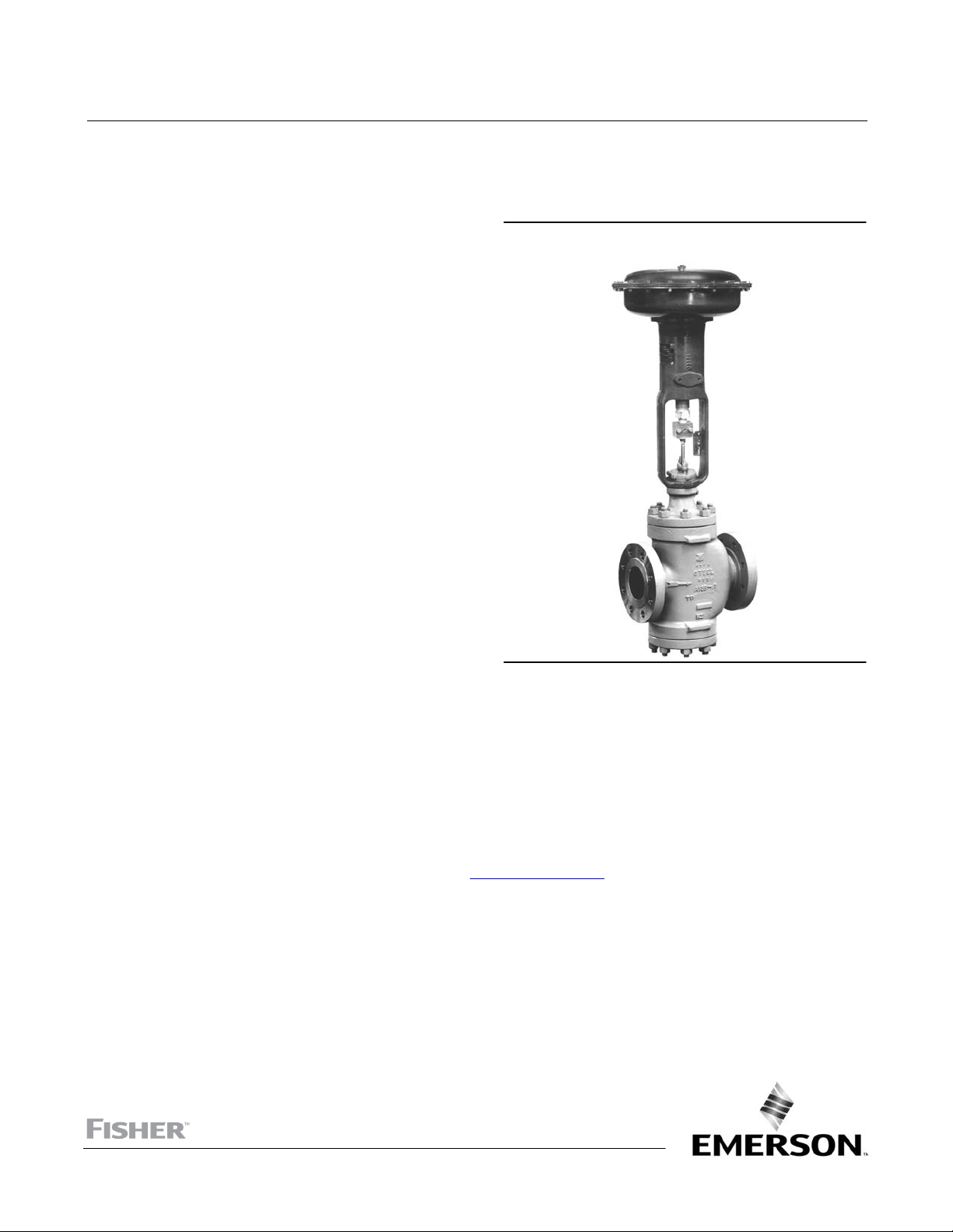
Figure 1. Fisher HS Control Valve with
Diaphragm Actuator
W6003-1
Introduction
Scope of Manual
This instruction manual provides installation, maintenance, and parts information for the NPS 1 through NPS 10 HS
control valves with ANSI CL900 through CL1500 pressure ratings. Refer to separate manuals for instructions on the
actuator and accessories.
Do not install, operate, or maintain a HS control valve without being fully trained and qualified in valve, actuator, and
accessory installation, operation, and maintenance. To avoid personal injury or property damage, it is important to
carefully read, understand, and follow all the contents of this manual, including all safety cautions and warnings. If you
have any questions about these instructions, contact your Emerson sales office
Description
These valves are either single-port or double-port constructions. Direct-acting valves have push-down-to-close action.
If the valve is installed in a horizontal pipe run and the actuator is vertical above the valve, downward motion of the
valve stem will close the valve.
HS valve plugs are, top-and- bottom guided. With top-and-bottom guiding, a bushing in the bottom flange and in the
bonnet guide the valve plug. Maintenance procedures in this manual are valid for either single or double-port valves.
before proceeding.
www.Fisher.com

HS Valve
June 2019
Table 1. Specifications
Instruction Manual
D100381X012
End Connection Styles
Buttwelding: Available in ASME B16.25 schedules that
are compatible with ASME B16.34
pressure/temperature ratings
Flanged: CL900 or CL1500 ring-type joint (RTJ) or
Flow Characteristics
Equal Percentage: V-Pup
Modified Parabolic: Throttle Plug
Quick Opening: Quick Opening Valve Plug
raised-face (RF) flanges per ASME B16.5
Pressure/Temperature Ratings
(1)
Consistent with CL900 or CL1500
pressure-temperature ratings per ASME B16.34
1. The pressure or temperature limits in this manual and any applicable standard or code limitations should not be exceeded.
Flow Direction
Single Port bodies are flow up
Double Port bodies (see figure 2)
Specifications
Typical specifications for HS control valves are shown in table 1.
Figure 2. Double-Port Fisher HS Valve with Top-and Bottom-Guided Throttle Plug Valve Plug
W0474‐1
Installation
WARNING
Always wear protective gloves, clothing, and eyewear when performing any installation operations to avoid personal
injury.
Personal injury or equipment damage caused by sudden release of pressure may result if the valve assembly is installed
where service conditions could exceed the limits given in table 1 or on the appropriate nameplates. To avoid such injury or
damage, provide a relief valve for over‐pressure protection as required by government or accepted industry codes and
good engineering practices.
Check with your process or safety engineer for any additional measures that must be taken to protect against process
media.
2
 Loading...