

Instruction Manual
D101618X012
DSA Desuperheater
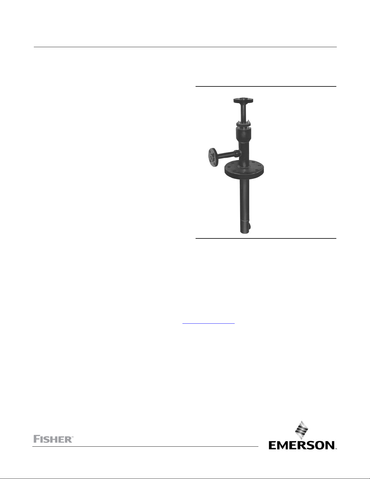
Fisher™ DSA Steam-Atomized Desuperheater
July 2017
Contents
Introduction 1.................................
Scope of Manual 1.............................
Description 1.................................
Principle of Operation 2.........................
Installation 2..................................
Operating Instructions 4.........................
Verification of Control Instrumentation 4.........
Maintenance Instructions 6......................
Servicing 7...................................
Troubleshooting 8..............................
Parts Ordering 8................................
Parts List 8....................................
Introduction
Figure 1. Fisher DSA Steam‐Atomized Desuperheater
W5366‐1
Scope of Manual
This instruction manual includes installation and operation information for the Fisher DSA steam‐atomized
desuperheater.
Do not install, operate, or maintain a DSA desupheater without being fully trained and qualified in valve, actuator, and
accessory installation, operation, and maintenance. To avoid personal injury or property damage, it is important to
carefully read, understand, and follow all the contents of this manual, including all safety cautions and warnings. If you
have any questions about these instructions, contact your Emerson sales office
proceeding.
or Local Business Partner before
Description
The DSA steam‐atomized desuperheater (figure 1) serves a wide range of desuperheating applications. It is best suited
for those installations requiring high rangeability in low steam velocity pipelines. With adequate controls, this unit
provides an efficient means of atomizing spraywater over wide fluctuations in flow rate while maintaining downstream
steam temperature to within 6 to 8_C (10 to 15_F) of saturation. The DSA desuperheater is easily installed directly into
the steam line. The standard mounting is with the desuperheater perpendicular to the steam line. However, the DSA
desuperheater can be made to fit angle or elbow installations.
www.Fisher.com

DSA Desuperheater
July 2017
Table 1. Specifications
Instruction Manual
D101618X012
Steam Line Sizes
J NPS 6 to 60
Steam Line Connection Sizes
NPS J 3, J 4, and J 6 J CL150, J CL300,
J CL600, J CL900, J CL1500, and J CL2500
raised‐face flange
Spraywater and Atomizing Steam Connection Sizes
NPS J 1, J 1-1/2, and J 2 J CL150, J CL300,
J CL600, J CL900, J CL1500, and J CL2500
Inherent Rangeability
Up to 50:1
Spraywater Pressure Required
3.5 to 35 bar (50 to 500 psi) greater than steam line
pressure
Minimum Steam Velocity
1.5 m/s (5 feet per second) depending on actual
operating conditions
raised‐face flange
Atomizing Steam
Maximum Inlet Pressures
Consistent with applicable CL150, 300, 600, 900,
1500, or 2500 pressure‐temperature ratings per
ASME B16.34
1. Do not exceed the pressure or temperature limits in this instruction manual, nor any applicable code or standard limitations.
2. Ratio of maximum to minimum controllable Cv.
(1)
Atomizing steam should be at least 2.0 times the
pressure of the steam to be desuperheated. Total
atomizing steam flow (lb/hr) will be 10 to 15 percent
of the maximum spraywater flow (lb/hr).
Principle of Operation
(2)
The DSA desuperheater utilizes the energy of atomizing steam to produce a fine spray of cooling water for injection
into the steam line. An external spraywater control valve controls the quantity of cooling water. The water flows into
the desuperheater and fills the main body of the unit just ahead of the atomizing head. Here the water is directed into
a number of flow channels where it is mixed and atomized by the high velocity atomizing steam (see figure 3).
The atomizing steam is controlled via an automatic or manual shutoff valve. The steam flows down the center of the
desuperheater body toward the atomizing head. Here too, the steam is directed into a number of flow channels. These
channels are sized to produce a critical pressure drop. This assures very high steam velocities and maximum kinetic
energy for spraywater atomization.
The atomizing steam mixes with the cooling water and produces a spraywater cloud with almost infinite surface area.
This spray cloud is almost instantaneously vaporized when injected into the main steam line, resulting in steam at a
reduced temperature.
The atomizing steam tube inside the desuperheater is only secured at the atomizing head. The packing box on top
allows for the free movement of the unit due to thermal expansion from steam/water temperature differentials.
Installation
WARNING
Always wear protective gloves, clothing, and eyewear when performing any installation operations to avoid personal
injury.
2

Instruction Manual
D101618X012
Personal injury or equipment damage caused by sudden release of pressure may result if the desuperheater is installed
where service conditions could exceed the limits given in table 1 or on the nameplate. To avoid such injury or damage,
provide a relief valve for over‐pressure protection as required by government or accepted industry codes and good
engineering practices.
Check with your process or safety engineer for any additional measures that must be taken to protect against process
media.
If installing into an existing application, also refer to the WARNING at the beginning of the Maintenance section in this
instruction manual.
DSA Desuperheater
July 2017
CAUTION
When ordered, the desuperheater configuration and construction materials were selected to meet particular pressure,
temperature, pressure drop, and fluid conditions. Do not apply any other conditions to the desuperheater without first
contacting your Emerson Automation Solutions sales office.
1. Insert the DSA desuperheater into the flanged pipe stud on the steam line (see figure 2 for the proper “T” length
dimension). Bolt the unit to the pipe in accordance with standard piping practice.
2. Clean and flush out the cooling water line before connecting to the desuperheater. Use only clean sources of
cooling water. Use of clean water decreases wear to the valve trim and prevents clogging of the desuperheater by
solid particles.
WARNING
Personal injury or property damage could result from clogging of the desuperheater. Emerson Automation Solutions
recommends installation of a strainer and isolating valve on the water line leading to the desuperheater. Failure to do so
may result in clogging of the desuperheater by solid particles, thus hampering temperature control of the steam.
3. A straight run of pipe is required downstream of the desuperheater to assure complete vaporization of cooling
water. Consult the desuperheater certified drawing for the required distance of straight pipe.
4. The temperature sensor should be mounted according to manufacturer's instructions. Minimum distance to the
sensor is approximately 9.1 m (30 feet) downstream of the desuperheater. This distance changes with higher
velocity steam flow and percentage of spraywater required. Consult the desuperheater certified drawing for the
exact distance.
5. Allow no branching out from the steam line, to divide the steam flow, between the temperature sensor and the
desuperheater.
A typical control loop is illustrated in figure 4. A temperature sensor generates a pneumatic instrument air signal
through a transmitter. This signal is transmitted to a remote mounted temperature indicating control station. The
output signal from the control station is sent to the positioner on the spraywater control valve. The positioner output
signal is piped to the actuator, which strokes the valve and controls the flow of cooling water to the desuperheater.
The atomizing steam valve is normally controlled so that it fully opens as soon as the spraywater control valve starts to
open.
WARNING
Personal injury could result from packing leakage. Valve packing was tightened prior to shipment; however some
readjustment will be required to meet specific service conditions.
3
 Loading...