

Fisher Instruction Manual: Fisher DMA, DMA/AF, and DMA/AF-HTC Mechanically Atomized Desuperheaters Manuals & Guides
Instruction Manual
D101617X012
DMA Desuperheater
Fisher™ DMA, DMA/AF, and DMA/AF‐HTC
Mechanically Atomized Desuperheaters
Contents
Introduction 2.................................
Scope of Manual 2.............................
Description 2.................................
Specifications 2...............................
Principle of Operation 3.........................
Installation 5..................................
Nozzle Maintenance and Replacement 6...........
DMA/AF and DMA/AF-HTC Desuperheater
Variable Geometry Nozzles 7.................
DMA Desuperheater Fixed Geometry Nozzles 8....
Troubleshooting 9.............................
Parts Ordering 14...............................
Parts List 14...................................
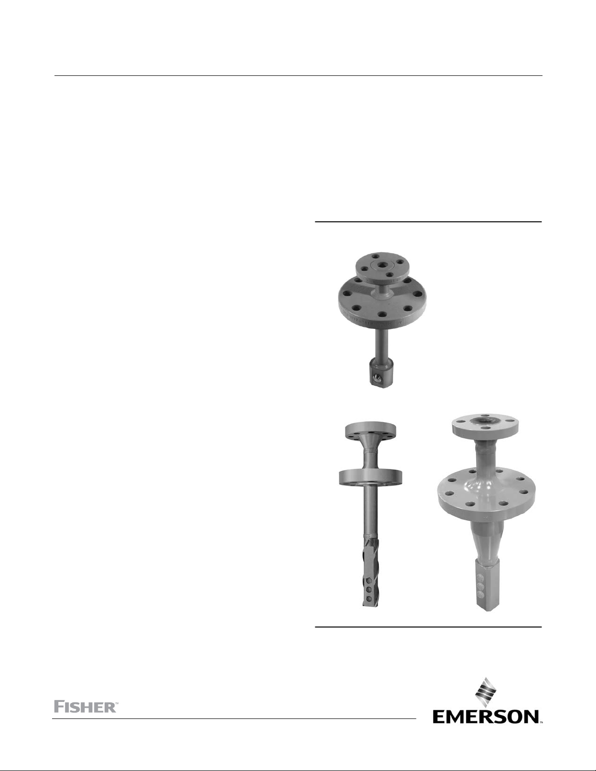
Figure 1. Fisher DMA, DMA/AF, and DMA/AF‐HTC
Desuperheaters
July 2017
W6298
DMA and DMA/AF
X0260
NPS 3 DMA/AF‐HTC
W8909‐1
NPS 4 DMA/AF‐HTC
www.Fisher.com

DMA Desuperheater
July 2017
Instruction Manual
D101617X012
Introduction
Scope of Manual
This instruction manual includes installation, maintenance, and operation information for the Fisher DMA, DMA/AF,
and DMA/AF‐HTC mechanically atomized desuperheaters.
Do not install, operate, or maintain these desuperheaters without being fully trained and qualified in valve, actuator,
and accessory installation, operation, and maintenance. To avoid personal injury or property damage, it is important
to carefully read, understand, and follow all the contents of this manual, including all safety cautions and warnings. If
you have any questions about these instructions, contact your local Emerson sales office
before proceeding.
Description
DMA, DMA/AF, and DMA/AF‐HTC desuperheaters (figure 1) can be used in many applications to effectively reduce the
temperature of superheated steam to the desired set point. Available variations are mechanically atomized (both fixed
geometry and variable geometry styles). Desuperheaters are available for installation in steam lines from DN 150
through DN 1500 (NPS 6 through 60) in diameter and are capable of maintaining steam temperatures to within 6_C
(10_F) of saturation temperatures.
or Local Business Partner
D DMA—A simple mechanically atomized desuperheater with single or multiple, fixed‐geometry spray nozzles is
intended for applications with nearly constant load. The DMA is installed through a flanged connection on the side
of a DN 150 (NPS 6) or larger pipeline. Maximum unit C
D DMA/AF—A variable‐geometry, mechanically atomized, back‐pressure‐activated desuperheater with one, two, or
three spray nozzles is designed for applications requiring control over moderate load fluctuations. The DMA/AF
desuperheater (figure 2) is installed through a flanged connection on the side of a DN 200 (NPS 8) or larger pipeline.
Maximum unit C
D DMA/AF‐HTC— The DMA/AF‐HTC is functionally equivalent to the DMA/AF, however it is structurally suited for more
severe applications. The most common applications include boiler interstage attemperation, where the
desuperheater is exposed to high thermal cycling and stress, high steam velocities and flow induced vibration. In
addition to this specific application, the DMA/AF‐HTC is suitable for other severe desuperheating application
environments. The DMA/AF‐HTC uses a construction optimized to move weld joints away from high stress regions.
The desuperheater design incorporates an integral thermal liner inside the desuperheater body pipe. This minimizes
the potential for thermal shock when cool water is introduced to the unit which has been heated to the operating
steam temperature.
The nozzle mount for the DMA/AF‐HTC is engineered to minimize the potential for excitation due to vortex shedding
and flow induced vibration. The DMA/AF‐HTC desuperheater (figure 3) is installed through a flanged connection on a
DN 200 (NPS 8) or larger pipeline. Maximum unit C
is 15.0.
V
V
V
is 15.0.
is 3.8.
Specifications
Specifications for the DMA, DMA/AF, and DMA/AF‐HTC desuperheaters are shown in table 1 and table 2.
2
Instruction Manual
D101617X012
Table 1. Specifications
DMA Desuperheater
July 2017
Steam Line Sizes
See table 2
Minimum Steam Velocity
DMA: 9.1 m/s (30 feet per second)
DMA/AF: 7.6 m/s (25 feet per second)
Steam Line Connection Sizes
DMA/AF‐HTC: 7.6 m/s (25 feet per second)
See table 2
Spraywater Connection Sizes
See table 2
Maximum Unit C
DMA: 3.8
DMA/AF: 15.0
Maximum Inlet Pressures
(1)
DMA/AF‐HTC: 15.0
Consistent with applicable CL150, 300, 600, 900,
1500, or 2500 pressure‐temperature ratings per
Construction Materials
ASME B16.34
Desuperheater Body (all designs except
Inherent Rangeability
(2)
DMA: Up to 3:1
DMA/AF: Up to 10:1
DMA/AF‐HTC: Up to 10:1
Spraywater Pressure Required
3.5 to 35 bar (50 to 500 psi) greater than steam line
pressure
1. Do not exceed the pressure or temperature limits in this instruction manual, nor any applicable code or standard limitations.
2. Ratio of maximum to minimum controllable C
.
v
DMA/AF‐HTC):
alloy steel (F22), or
Desuperheater Body (DMA/AF‐HTC):
(SA105) or
Note: NPS 3 will have body-matched cast equivalent
material for nozzle mount
Nozzle Material
DMA:
J 303 orJ 316, stainless steel
DMA/AF, DMA/AF‐HTC:
(for Spraywater Flow)
v
J Carbon steel, J Chrome‐moly
J 300 series stainless steel
J Carbon Steel
J Chrome‐moly alloy steel (F22, F91)
J 410 stainless steel
Table 2. Connection Sizes
DESIGN STEAM LINE SIZE
DMA DN 150 - DN 1500 DN 80, 100, or 150
DMA/AF DN 200 - DN 1500
DMA/AF‐HTC DN 200 - DN 1500 DN 80 or 100
DMA NPS 6 - NPS 60 NPS 3, 4, or 6
DMA/AF NPS 8 - NPS 60 NPS 3
DMA/AF‐HTC NPS 8 - NPS 60 NPS 3 or 4
1. Other standard flanges and connections are also available.7
2. Consult your local Emerson sales office
3. NPS 1‐1/2 spraywater connection is only available for CL150 - 900.
or Local Business Partner for acceptability of NPS 3 mounting connection for size and pressure class specified.
DN 80
Size, NPS
(2)
(2)
STEAM LINE CONNECTION SPRAYWATER CONNECTION
Raised‐Face Flange
Rating
metric
, 100, 150, or
200
, 4, 6, or 8
PN 20, 50, 100
PN 20, 50, 100, 150,
250, or 420
ASME
CL150, 300, 600
CL150, 300, 600, 900,
1500, or 2500
(1)
DN 25, 40, or 50
DN 25, 40, 50, 65, or
DN 40
NPS 1, 1‐1/2, or 2
NPS 1, 1‐1/2, 2, 2‐1/2,
NPS 1‐1/2
Size
80
(3)
or 3
, or 50
(3)
, or 2
Raised‐Face Flange
Rating
PN 20, 50, 100, 150,
250, or 420
PN 20, 50, 100, 150,
250, or 420
CL150, 300, 600, 900,
1500, or 2500
CL150, 300, 600, 900,
1500, or 2500
(1)
Principle of Operation
The DMA, DMA/AF, and DMA/AF‐HTC desuperheaters reduce steam temperatures through the introduction of cooling
water directly into the hot steam flow stream. By regulating the quantity of water that is injected, accurate
downstream steam temperature can be both controlled and maintained.
3
DMA Desuperheater
July 2017
Instruction Manual
D101617X012
The rate of vaporization, and/or cooling, is a function of droplet size, distribution, mass flow, and temperature. Steam
velocity is critical and should be maintained at 6.1 to 9.1 meters per second (20 to 30 feet per second) as the
minimum. Actual minimum steam velocity requirements will vary by application. As steam velocity increases, a longer
distance is required to achieve homogeneous mixing and to complete vaporization.
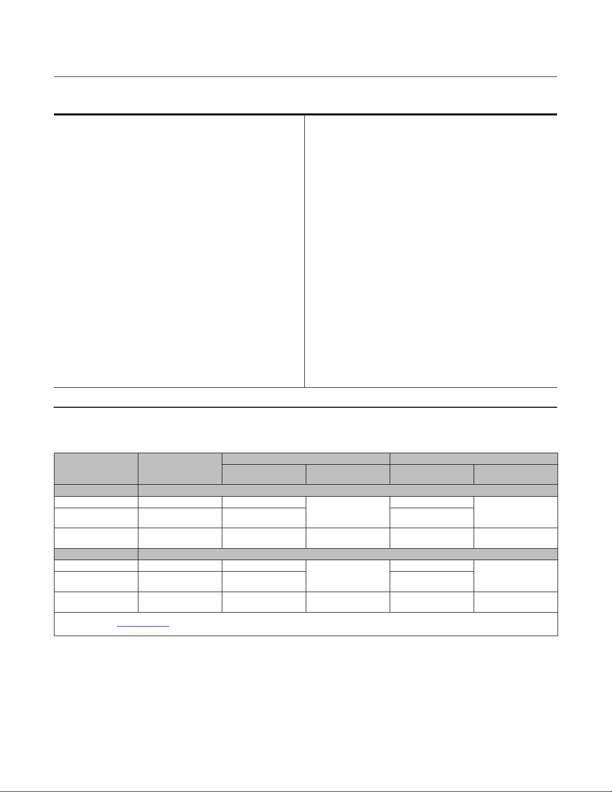
In both DMA desuperheater nozzle styles, the spraywater quantity is controlled by an external control valve which
responds to signals received from the temperature control system. The water enters the main tube of the
desuperheater, passes through the spray nozzle, and discharges into the steam line as a fine, atomized spray (see
figure 2).
Each particular nozzle, or set of nozzles, in the sprayhead is tailored to meet a specific set of operating conditions. The
nozzle design optimizes the spraywater droplet size promoting rapid atomization and complete vaporization of water
in the steam flow stream to obtain precise temperature control. The DMA desuperheater uses a fixed geometry
nozzle, while the DMA/AF desuperheater uses a variable geometry AF nozzle. In the AF nozzle design (see figure 5),
water enters the swirl chamber via compound angled orifices, thus creating a rotational flow stream. This flow stream
is further accelerated as it is forced up and out through the spray annulus. The cone‐shaped plug varies the geometry
of the spray annulus using a force balance principle between water pressure and the preload exerted by a helical
spring. This variable geometry design sprays a thin hollow cone over a wide range of flow rates, resulting in excellent
temperature control over a wide range of operating conditions.
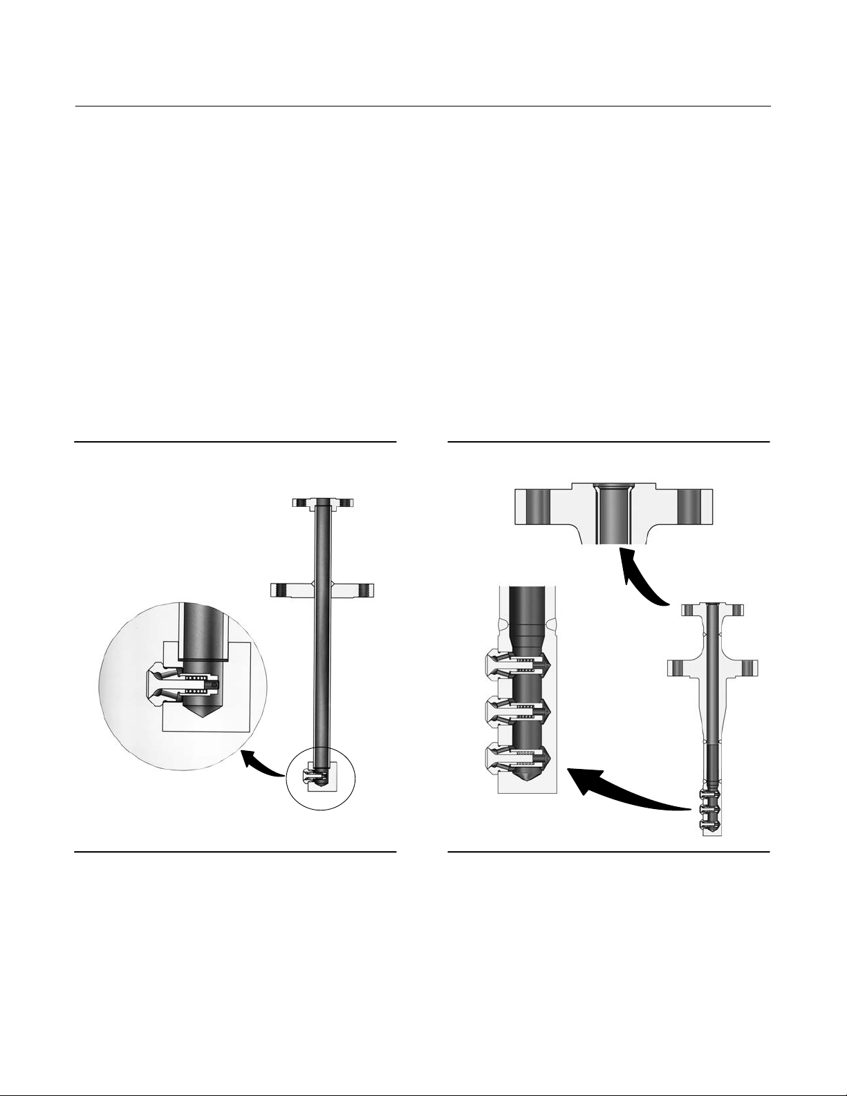
Figure 2. Detail of Fisher DMA/AF Desuperheater Figure 3. Detail of Fisher DMA/AF‐HTC
Desuperheater
W6310‐1
4
W8908‐1

Instruction Manual
D101617X012
Figure 4. Typical Fisher DMA, DMA/AF, or DMA/AF‐HTC Desuperheater Installation
FISHER
SPRAYWATER
CONTROL VALVE
Note 1
TC
SPRAYWATER
DMA DESUPERHEATER
STEAMFLOW
DMA Desuperheater
July 2017
Note 2
B2317
Notes:
1. TC - Temperature-Indicating Controller
2. TE - Temperature Sensor Element
Installation
WARNING
Always wear protective gloves, clothing, and eyewear when performing any installation operations to avoid personal
injury.
Personal injury or equipment damage caused by sudden release of pressure may result if the desuperheater is installed
where service conditions could exceed the limits given in table 1 or on the nameplate. To avoid such injury or damage,
provide a relief valve for over‐pressure protection as required by government or accepted industry codes and good
engineering practices.
Check with your process or safety engineer for any additional measures that must be taken to protect against process
media.
If installing into an existing application, also refer to the WARNING at the beginning of the Maintenance section in this
instruction manual.
CAUTION
When ordered, the desuperheater configuration and construction materials were selected to meet particular pressure,
temperature, pressure drop, and fluid conditions. Do not apply any other conditions to the desuperheater without first
contacting your local Emerson Automation Solutions sales office representative.
1. Mount the DMA, DMA/AF, or DMA/AF‐HTC desuperheater in a “Tee” piece at the desired location in the pipe, in
accordance with standard piping practice. The nozzle should be positioned in the top quadrant of the pipe (see
figure 6 or 7 for the proper “T” length dimension).
5
 Loading...