

Instruction Manual: Fisher D4 Control Valve with Gen 2 easy-Drive Electric Actuator
Table of contents
 Loading...
Fisher Instruction Manual: Fisher D4 Control Valve with Gen 2 easy-Drive Electric Actuator Manuals & Guides

Instruction Manual
D104188X012
D4 Valve with Gen 2 easy-Drive Actuator
April 2022
Fisher™ D4 Control Valve with Gen 2 easy-Drive
Electric Actuator
Contents
Introduction 1.................................
Scope of Manual 1.............................
Description 3.................................
Specifications 3...............................
Educational Services 3.........................
Installation 4..................................
Special Instructions for “Safe Use” and Installations
in Hazardous Locations 5.....................
Startup Overview 6............................
Default Input Signals 11........................
Configuration 11..............................
Input Configuration 11.....................
Changing the Inputs from Default Settings 11..
Modbus Setup 11.............................
Connecting using the Fisher easy-Drive
configuration software 12................
Initial Setup 12............................
Calibration Instructions 13..................
Licensing 16..............................
Startup 18................................
Troubleshooting 19.............................
Maintenance 20................................
Valve Plug and Seat Ring 20.....................
Valve Packing 22..............................
Parts Ordering 27...............................
Parts Kits 27...................................
Figure 1. Fisher D4 Control Valve with Gen 2
easy-Drive Electric Actuator
W9933-5
Repair Kits 27..................................
Parts List 28...................................
Appendix A - Modbus 31.........................
Appendix B - Certificate of Conformance 36.........
™
Introduction
Scope of Manual
This instruction manual provides installation, maintenance, and parts information for the Fisher D4 control valve with
Gen 2 easy-Drive electric actuator. For Gen 1 electric actuators, use Fisher D4 with easy-Drive Instruction Manual,
(
D103597X012). If the actuator has a RPU-100 installed refer to easy-Drive RPU-100 Instruction Manual,
(D104551X012
www.Fisher.com
).
Do not install, operate, or maintain a D4 control valve with Gen 2 easy-Drive electric actuator without
being fully trained and qualified in valve, actuator, and accessory installation, operation, and
maintenance. To avoid personal injury or property damage, it is important to carefully read, understand,
and follow all the contents of this manual, including all safety cautions and warnings. If you have any
questions about these instructions, contact your Emerson sales office
before proceeding.

D4 Valve with Gen 2 easy-Drive Actuator
April 2022
Table 1. Specifications
Instruction Manual
D104188X012
Valve Body Sizes and End Connection Styles
(1)
See table 2
Maximum Inlet Pressures and Temperatures
(1)
If the valve nameplate shows an ASME
pressure‐temperature class, maximum inlet pressure
and temperature is consistent with the applicable
class per ASME B16.34. If the nameplate does not
show an ASME class, it will show a maximum cold
working pressure at 38_C (100_F) (for example, 293
bar [4250 psi])
Maximum Pressure Drops
(1)
See table 4
Shutoff Classification per ANSI/FCI 70‐2
and IEC 60534‐4
Class IV
Material Temperature Capabilities
(1)
Valve Body Assembly:
Standard Bonnet O‐Ring: -40 to 135°C (-40 to 275°F)
Optional Fluorocarbon Bonnet O‐Ring: -23 to 204°C
(-10 to 400°F)
Flow Characteristic
Equal percentage
Flow Direction
Flow up only
Port Diameters
See table 2
Power Requirements
11-30 VDC, minimum 4 amp power supply required
(fuse to 5 amps)
Maximum Current Draw
4 amps
Idle Current Draw
15 mA at 24 VDC, 25 mA at 12 VDC
Conduit Connections
Two 3/4 NPT connections
Stroke Length
19 mm (0.75 inch)
Nominal Stroke Speed
(2)
3.9 mm/s (0.15 inch/s) at 24 VDC
2.2 mm/s (0.09 inch/s) at 12 VDC
Hazardous Area Approvals
CSA (C/US): ExplosionProof Class I, Division 1,
Groups C and D, T6, Ex db IIA T6, Class I, Zone 1,
AEx db IIA T6
ATEX Flameproof - Gas:
II 2 G, Ex db IIA T6 Gb
IECEx Flameproof - Gas: Ex db IIA T6 Gb
Enclosure Rating
Type 4X and IP66
Valve Plug Travel
19 mm (0.75 inch)
Valve Plug Style
Micro‐Form valve plug
Available Actuator Configurations
On/off (snap acting)
Positioning (flow or pressure control)
1. The pressure or temperature limits in the referenced tables and any applicable ASME code limitations should not be exceeded.
2. 10% variation can be expected, based on temperature and pressure of application.
2
Duty Cycle
50% maximum
Enclosure Material
Cast aluminum alloy with powder coat paint
Approximate Weight:
22 - 51 kg (49 - 113 lbs), depending upon
construction

Instruction Manual
D104188X012
D4 Valve with Gen 2 easy-Drive Actuator
April 2022
Description
The D4 control valve with easy-Drive electric actuator is a compact, rugged valve designed primarily for high‐pressure
throttling applications. This valve is ideal for use on pressure and flow control applications within the oil and gas
production industry. The D4 valve also makes an excellent dump valve for high‐pressure separators and scrubbers.
The D4 control valve meets the metallurgical requirements of NACE MR0175/ISO 15156 without environmental limits
for temperatures below 135_C (275_F). If the temperature is above 135_C (275_F), the N07718 Belleville washers will
impose some limits, as shown in table 3.
Specifications
Table 1 lists specifications for the D4 control valve with easy-Drive electric actuator. Some of the specifications for a
given control valve as it originally comes from the factory are stamped on a nameplate located on the lower actuator
enclosure.
Educational Services
For information on available courses for the Fisher D4 control valve with easy-Drive electric actuator, as well as a
variety of other products, contact:
Emerson Automation Solutions
Educational Services - Registration
Phone: 1-641-754-3771 or 1-800-338-8158
E-mail: education@emerson.com
emerson.com/fishervalvetraining
Table 2. Valve Sizes and Connection Styles
VALVE
SIZE,
NPS
1
2
X = Available construction.
PORT
DIAMETER,
(INCHES)
0.25, 0.375,
0.5, 0.75
0.25, 0.375, 0.5
0.75, 1, 1.25
SCREWED RAISED FACE (RF) FLANGED
4250 psi CL150 CL300 CL600
X X X X X X X
X X X X X X X
Table 3. D4 Environmental Limits for NACE MR0175/ISO 15156 with Sour Trim
MAXIMUM TEMPERATURE MAXIMUM H2S PARTIAL PRESSURE
_C _F MPa psia
232 450 0.2 30 No
204 400 1.4 200 No
199 390 2.3 330 No
191 375 2.5 360 No
149 300 2.8 400 No
135 275 No Limit Yes
CL900 and
CL1500
RING TYPE JOINT
(RTJ) FLANGED
CL600
COMPATIBLE WITH
ELEMENTAL SULFUR
CL900 and
CL1500
3

D4 Valve with Gen 2 easy-Drive Actuator
April 2022
Instruction Manual
D104188X012
Table 4. Fisher D4 easy-Drive Maximum Pressure Drop
PORT DIAMETER MAXIMUM PRESSURE DROP
mm Inch Bar psi
6.4
9.5
12.7
19.1
25.4
31.8
1. Downstream pressure, P2, is limited to 2250 psig.
0.25
0.375
0.5
0.75
1
1.25
293
293
247
105
56
34
(1)
4250
4250
3576
1518
814
495
(1)
(1)
(1)
Installation
WARNING
Always wear protective gloves, clothing, and eyewear when performing any installation operations to avoid personal
injury.
To avoid personal injury or property damage caused by bursting of pressure‐retaining parts or by uncontrolled process
fluid, be certain the service conditions do not exceed the limits shown on the valve nameplate and in table 1. Use
pressure‐relieving devices required by government or accepted industry codes and good engineering practices.
Check with your process or safety engineer for any additional measures that must be taken to protect against process
media.
If installing into an existing application, also refer to the WARNING at the beginning of the Maintenance section in this
instruction manual.
WARNING
For explosionproof applications, ensure the actuator cover is properly bolted before applying power to the actuator.
Personal injury or property damage may result from fire or explosion if power is applied to the actuator with the cover
removed in a hazardous area.
For explosion‐proof applications, install rigid metal conduit and a conduit seal no more than 457 mm (18 inches) from the
actuator. Personal injury or property damage may result from explosion if the seal is not installed.
Select wiring and/or cable glands that are rated for the environment of use (such as hazardous area, ingress protection, and
temperature). Failure to use properly rated wiring and/or cable glands can result in personal injury or property damage
from fire or explosion.
Wiring connections must be in accordance with local, regional, and national codes for any given hazardous area approval.
Failure to follow the local, regional, and national codes could result in personal injury or property damage from fire or
explosion.
CAUTION
When ordered, the valve configuration and construction materials were selected to meet particular pressure, temperature,
pressure drop, and controlled fluid conditions. Responsibility for the safety of process media and compatibility of valve
materials with process media rests solely with the purchaser and end‐user. Since some body/trim material combinations
are limited in their pressure drop and temperature ranges, do not apply any other conditions to the valve without first
contacting your Emerson sales office
To avoid product damage, inspect the valve before installation for any damage or any foreign material that may have
collected in the valve body. Also remove any pipe scale, welding slag, or other foreign material from the pipeline.
.
4

Instruction Manual
D104188X012
D4 Valve with Gen 2 easy-Drive Actuator
April 2022
WARNING
Avoid personal injury or property damage caused by possible actuator failure. The use of a rigidly‐mounted support on the
actuator casing may cause additional stress on the actuator leading to premature wear and/or failure of the actuator
components.
CAUTION
To avoid product damage, inspect the valve before installation for any damage or any foreign material that may have
collected in the valve body. Also remove any pipe scale, welding slag, or other foreign material from the pipeline.
1. Before installing the control valve assembly, inspect it for any damage and for any foreign material that may have
collected in the valve body.
2. Remove any pipe scale, welding slag, and other foreign material from the pipeline.
3. The control valve can be installed in any position, but normally the actuator is vertical above the valve. Install the
valve so the flow direction arrow on the side of the valve indicates the direction of the process flow.
4. Install the valve following local and national piping codes when they apply to the application. For screwed
connections, treat the external pipe threads with a good grade pipe compound. For flanged valves, use suitable
gaskets between valve and pipeline flanges.
5. If continuous operation is required during maintenance and inspection, install a conventional three‐valve bypass
around the valve.
Special Instructions for “Safe Use” and Installations in Hazardous Locations
ATEX/IECEx
WARNING
To avoid static discharge from the enclosure, do not rub or clean the enclosure with solvents. To do so could result in an
explosion. Clean with a mild detergent and water only.
The enclosure is nonconducting and may generate an ignitioncapable level of electrosatic charges under certain extreme
conditions. The user should ensure that the equipment is not installed in a location where it may be subjected to external
conditions (such as highpressure steam) which might cause a buildup of electrostatic charges on nonconducting surfaces.
Additionally, cleaning of the equipment shall only be done with a damp cloth.
To avoid damage to the enclosure, when screws are fully tightened into blind holes in enclosure walls, with no washer
fitted, at least one full thread shall remain free at the base of the hole.
5
D4 Valve with Gen 2 easy-Drive Actuator
April 2022
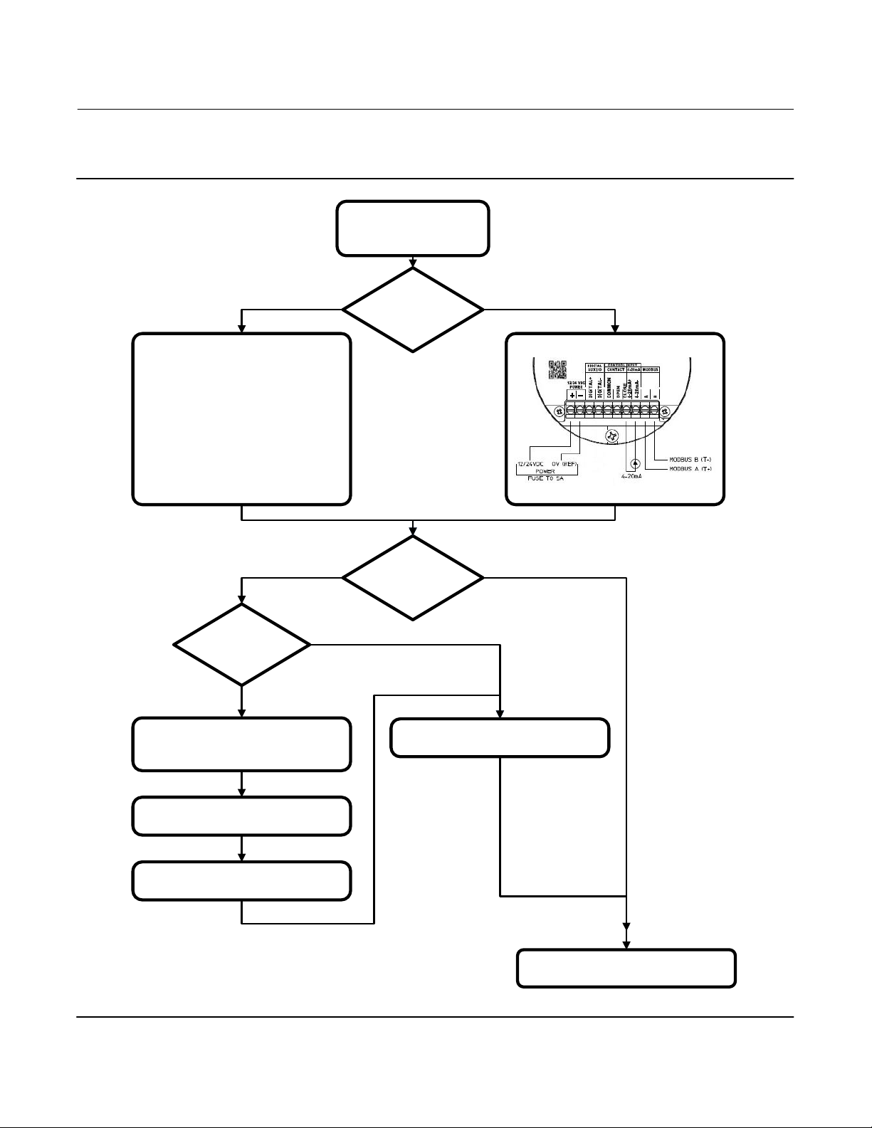
Startup Overview
Figure 2. Flowchart
Instruction Manual
D104188X012
PREPARE PER INSTRUCTIONS
IN INSTALLATION SECTION
ON/OFF
WIRE PER DIAGRAM FOR L2e
YES
FIRST TIME USING
Modbus?
NO
POSITIONING OR
ON/OFF?
ARE YOU USING
Modbus?
POSITIONING
WIRE PER DIAGRAM FOR 4-20 mA
NO
YES
CONNECT USB-TO-Modbus CONVERTER
TO INTERNET CONNECTED COMPUTER
FOLLOW DRIVER INSTALLATION
INSTRUCTIONS FOR YOUR DEVICE
INSTALL easy-Drive CONFIGURATION OR
Modbus MASTER SOFTWARE
6
CONNECT VIA Modbus TO VALVE AND
MONITOR DESIRED REGISTERS
UNIT IS READY FOR OPERATION

Instruction Manual
D104188X012
Figure 3. Fisher D4 Valve with Gen 2 easy-Drive Actuator Wiring Diagram
CONTROLLER
POWER AND
CONTROL TERMINAL
MOTOR / GEARBOX ASSY
(GE84238)
GE47302-7
D4 Valve with Gen 2 easy-Drive Actuator
April 2022
FIELD WIRING CONNECTIONS
TOP VIEW CONTROLLER
Power Requirements
Ensure a stable DC power source is available, maintaining less than 5% ripple and sufficiently surge protected for the
application. A 4 amp (minimum) power supply is required.
Wiring Instructions
1. Observe local wiring requirements for hazardous location usage.
2. Conduit seals within 450 mm (18 inches) of the enclosure port are required for explosionproof installation.
3. 18 AWG (0.52 mm
2
) to 12 AWG (3.31 mm2) wire size required.
4. Fuse system to 5A.
5. Connect enclosure and analog signal shields.
6. Ensure power is turned off before connecting the wires.
Power
1. Connect 12 or 24 VDC reference to: –
2. Connect 12 or 24 VDC positive to: +
3. Be sure to tighten terminals sufficiently to ensure solid mechanical connection.
7
D4 Valve with Gen 2 easy-Drive Actuator
April 2022
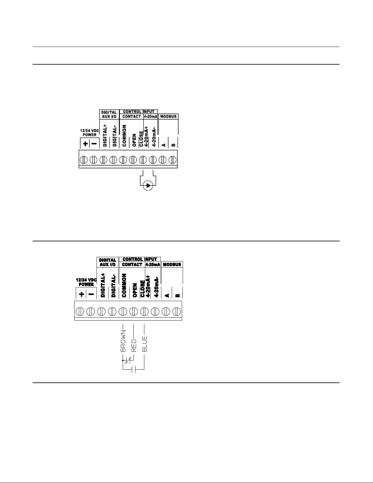
Figure 4. Wiring - Analog Input
Instruction Manual
D104188X012
Figure 5. Wiring - L2e
8

Instruction Manual
D104188X012
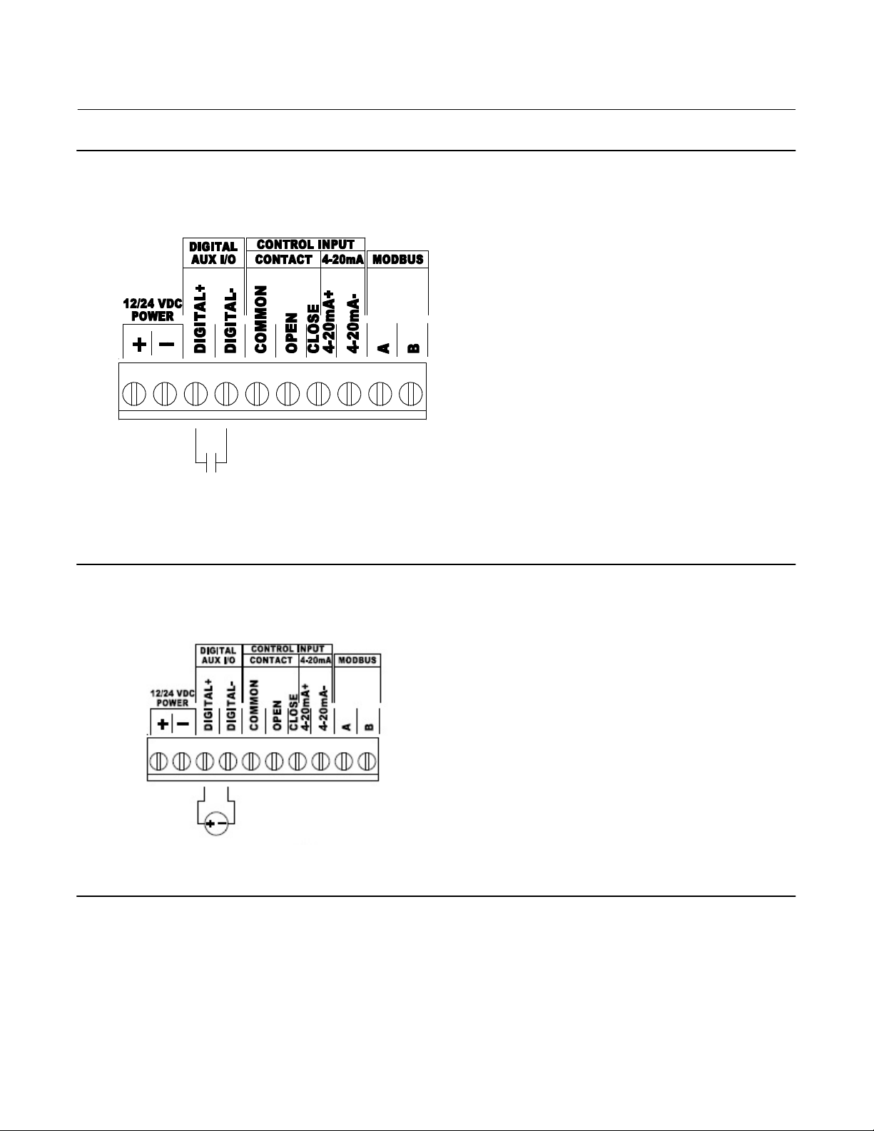
Figure 6. Wiring - Single Dry Contact
D4 Valve with Gen 2 easy-Drive Actuator
April 2022
Figure 7. Wiring - Modbus Input
9
D4 Valve with Gen 2 easy-Drive Actuator
April 2022
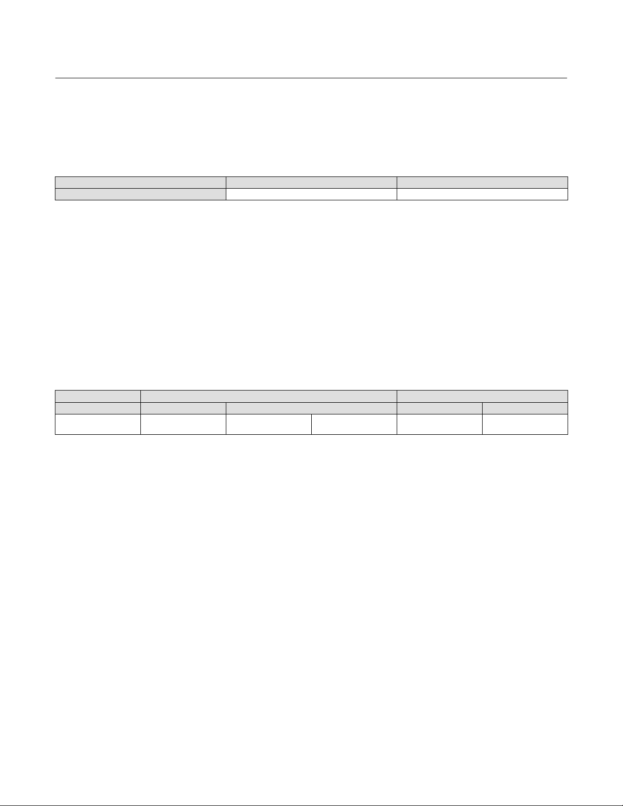
Figure 8. Wiring - Auxiliary Digital I/O set to input (40080=0)
Instruction Manual
D104188X012
Figure 9. Wiring - Auxiliary Digital I/O set to output (40080=1)
10 V, 25 mA max
10
Instruction Manual
D104188X012
D4 Valve with Gen 2 easy-Drive Actuator
April 2022
Default Input Signals
The D4 with easyDrive comes from the factory calibrated and ready for use with the following default input signals
shown in table 5.
Table 5. D4 easy-Drive Default Input Signals
CONFIGURATION ON/OFF POSITIONING
Input Signal L2e (dual dry contact) 4-20 mA
If the input signal of the application matches table 5, proceed to the Wiring Instructions section. If the input signal of
the application does not match table 5, proceed to the Configuration section.
Configuration
Input Configuration
There are two functional configurations available for the easyDrive electric actuator: On/Off and Positioning. It is
possible to change an actuator from On/Off to Positioning after it has been delivered from the factory using a
positioning license key. See licensing section.
All available input signals are shown in table 6.
Table 6. All Available Input Signals
CONFIGURATION ON/OFF POSITIONING
Control Source Modbus Local Modbus Local
Input Signal Modbus
L2e Dual Dry Contact
(default)
Single Dry Contact Modbus 4-20 mA (default)
If you are using the default inputs signals, and the valve has not been disassembled or adjusted in any way, there is no
need to recalibrate the assembly. You can proceed directly to Startup (page 18).
Changing the Inputs from Default Settings
All configuration within the valve is done by setting values in Modbus registers. This can be done using any Modbus
master (flow computer, PLC, PC). Configuration software, providing a visual interface to the registers, is available
through your Emerson sales office or the Fisher website, at www.fisher.com/easyDrive.
Modbus setup
Use of a serial or USB to RS-485 device is required to connect to the actuator. Refer to manufacturer's requirements for
installation. The D4 with easyDrive electric actuator Modbus factory defaults are Address 1, 9600 baud, even parity, 1
stop bit, MSB.
When a connection has been achieved, the actuator may be configured to accept the input signal over the Modbus
link (ignoring the physical inputs) and the Modbus settings may be changed to accommodate the network to which it
is attached. Other changes to functionality are possible, such as:
D Low level cutoff: 40054 (default is 5%)
D Position upon loss of signal: 40053 (default is 0%)
See Appendix A for a full map of Modbus registers and their functions.
11

D4 Valve with Gen 2 easy-Drive Actuator
April 2022
Figure 10. Fisher easy-Drive Configuration Software
Instruction Manual
D104188X012
Connecting using the Fisher easyDrive configuration software
The Fisher easyDrive configuration software allows configuration and diagnosing of the Fisher easyDrive electric
actuator with a graphical interface. Connect a PC to the actuator using a USB or serial device to Modbus RTU converter
using the wiring instructions above. The USB or serial device will be visible in the drop menu under Serial Port Settings.
Baud rate and parity should be set to the Modbus settings of the actuator. Default actuator settings are address 1,
9600 baud, even parity, 1 stop bit, MSB. Press the AUTO button in the upper left corner to connect to the valve.
Use the Fisher easyDrive configuration software (figure 10) to make the desired changes, or register values may be
changed to allow different functionality.
Note
If an actuator is on/off, a Modbus command of 0499 in register 40001 will cause the valve to close fully, while a value of 5001000
will cause the valve to open fully. The command register has one implied decimal point.
Initial Setup
The control method selection determines what control signal to which the valve will respond. Only the control signal
selected will result in movement of the valve; all others will be ignored. The control methods available are dependent
upon the licensing tier purchased with the valve. The functions for each tier are shown below.
D On/Off Tier
12
Loading...