

Fisher Instruction Manual: Fisher 8540 Eccentric Disk Butterfly Control Valve Manuals & Guides

Instruction Manual
D104709X012
Fisher™ 8540 Eccentric Disk
Butterfly Control Valve
8540 Valve
September 2021
Contents
Introduction 1.................................
Scope of Manual 1.............................
Description 1.................................
Specifications 2...............................
Installation 2..................................
Valve Orientation 4............................
Maintenance 8.................................
Packing Maintenance 9.........................
Seal Ring Maintenance 11......................
Disk, Drive Shaft and Bearing Maintenance 15......
Actuator Mounting 18.........................
Parts Ordering 19...............................
Parts List 20...................................
Figure 1. Fisher 8540 Butterfly Valve with Bettis RPE
Actuator and 3720 Positioner
X1846
Introduction
Scope of Manual
This instruction manual includes installation, maintenance, and parts information for the 8540 Eccentric Disk Butterfly
Control Valve (see figure 1). Refer to separate instruction manuals for information covering the actuator and
accessories.
Do not install, operate, or maintain 8540 valves without being fully trained and qualified in valve,
actuator, and accessory installation, operation, and maintenance. To avoid personal injury or property
damage, it is important to carefully read, understand, and follow all the contents of this manual,
including all safety cautions and warnings. If you have any questions about these instructions, contact
your Emerson sales office
before proceeding.
Description
The seal design of the 8540 eccentric disk high performance butterfly valve provides excellent shutoff capability. This
valve has a square drive shaft end and soft seal rings for use in a wide variety of applications.
www.Fisher.com
8540 Valve
September 2021
Table 1. Specifications
Instruction Manual
D104709X012
Valve Size and End Connection Styles
NPS J 3,J 4,J 6,J 8,J 10, and
Flow Direction
See figure 3
J 12 wafer body valves
Maximum Inlet Pressure
(1)
Carbon Steel and Stainless Steel Valve Bodies:
Consistent with CL150 and 300
pressure/temperature ratings per ASME B16.34
Actuator/Valve Action
With the diaphragm or piston actuators, the valve
action is field‐reversible. Refer to information in the
Installation section.
unless limited by material temperature capabilities.
Shutoff Classifications
J PTFE Seal: Bidirectional shutoff to Class VI per
ANSI/FCI 70‐2 and IEC 60534‐4.
Valve Classification
Face‐to‐face dimensions meet API 609 or MSS‐SP‐68
standards for face‐to‐face dimensions of wafer‐style
valves.
Flow Characteristics
Approximately linear
Shaft Diameters
See table 2
Disk Rotation
Clockwise to close (when viewing from the drive shaft
end) through 90 degrees of disk rotation (see figure
8)
1. The pressure/temperature limits in this manual and any applicable standard or code limitation for valves should not be exceeded.
Approximate Weights
See table 2
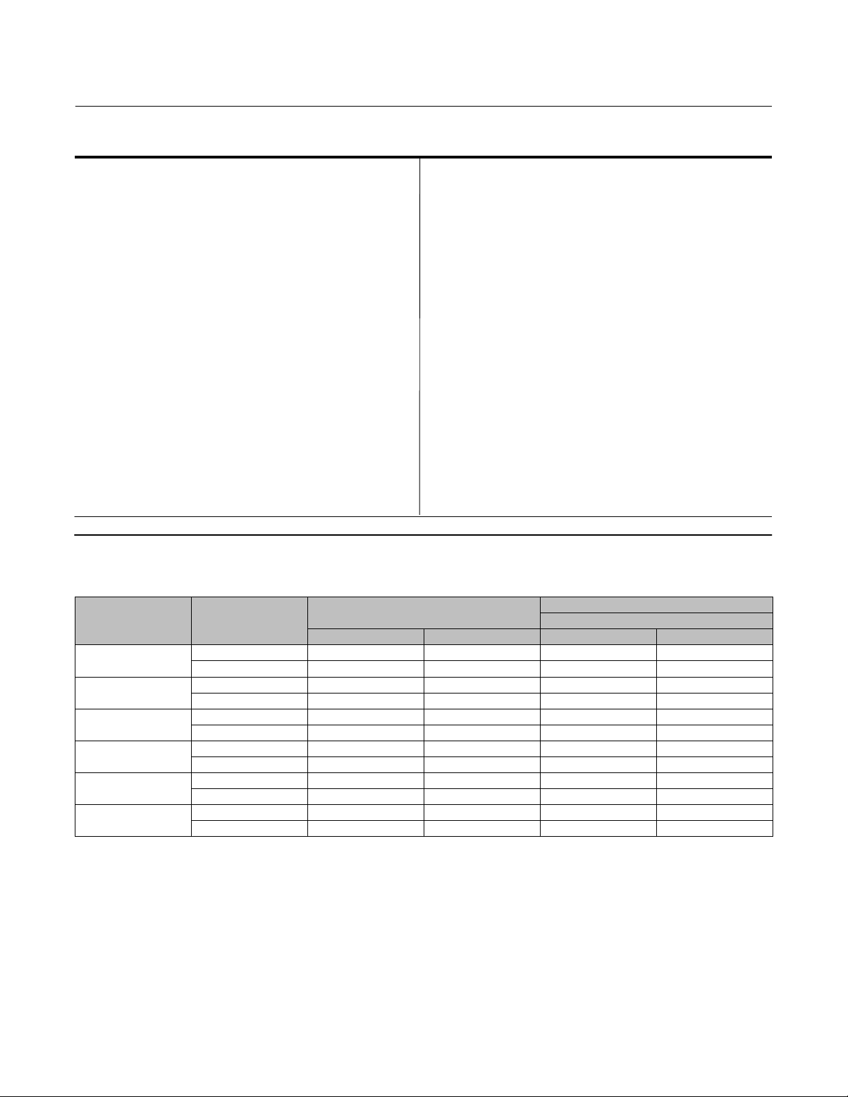
Table 2. Valve Size, Shaft Diameter, and Approximate Weight
APPROXIMATE WEIGHT
Wafer‐Style
VALVE SIZE, NPS CLASS
3
4
6
8
10
12
150 12.7 1/2 4.5 10
300 15.9 5/8 5.9 13
150 15.9 5/8 8.6 19
300 19.1 3/4 10 23
150 19.1 3/4 13 29
300 25.4 1 15 33
150 25.4 1 21 47
300 31.8 1‐1/4 24 53
150 31.8 1‐1/4 34 75
300 38.1 1‐1/2 44 96
150 38.1 1‐1/2 49 107
300 44.5 1‐3/4 64 141
SHAFT DIAMETER
mm Inches kg Pounds
Installation
The valve is normally shipped as part of a control valve assembly, with the power actuator mounted on the valve. If the
valve or actuator have been purchased separately, or if the actuator has been removed for maintenance, mount the
actuator on the valve, and adjust actuator travel before inserting the valve body into the line. This is necessary due to
the measurements that must be made during the actuator calibration adjustment process. Refer to the Actuator
Mounting section of this manual to mount the actuator on the valve. Refer to the actuator instruction manual for
mounting and adjusting instructions before proceeding.
2

Instruction Manual
D104709X012
8540 Valve
September 2021
WARNING
Always wear protective gloves, clothing, and eyewear when performing any installation operations to avoid personal
injury.
To avoid personal injury or property damage resulting from the sudden release of pressure, do not install the valve
assembly where service conditions could exceed the limits given in this manual, the limits on the appropriate nameplates,
or the matching pipe flange rating. Use pressure‐relieving devices as required by government or accepted industry codes
and good engineering practices.
Check with your process or safety engineer for any additional measures that must be taken to protect against process
media.
If installing into an existing application, also refer to the WARNING at the beginning of the Maintenance section in this
instruction manual.
WARNING
When ordered, the valve configuration and construction materials were selected to meet particular pressure, temperature,
pressure drop, and controlled fluid conditions. Responsibility for the safety of process media and compatibility of valve
materials with process media rests solely with the purchaser and end-user. To avoid possible personal injury and because
some valve/trim material combinations are limited in their pressure drop and temperature ranges, do not apply any other
conditions to the valve without first contacting your Emerson sales office
.
Table 3. Construction Material Temperature Limits
COMPONENTS AND MATERIALS OF
CONSTRUCTION
Valve Body Material
Carbon Steel
CF8M
Disk Material
CF8M -198 to 538 -325 to 1000
Shaft Material
S17400 -62 to 427 -80 to 800
Bearing Material
PEEK / PTFE lined -46 to 232 -50 to 450
Packing Material
PTFE V-Rings -46 to 232 -50 to 450
Seal Ring
PTFE (standard) Soft Seal Ring -46 to 232 -50 to 450
1. Refer to Ordering Matrix for 8540 Valves. For selection temperatures not shown above, contact your Emerson sales office.
(1)
TEMPERATURE LIMITS
_C _F
-29 to 427
-198 to 538
-20 to 800
-325 to 1000
1. Install a three‐valve bypass around the control valve assembly if continuous operation is necessary during
inspection and maintenance of the valve.
2. Inspect the valve to be certain that it is free of foreign material.
CAUTION
Be certain that adjacent pipelines are free of any foreign material, such as pipe scale or welding slag, that could damage the
valve sealing surfaces.
3
8540 Valve
September 2021
Instruction Manual
Table 4. Maximum Allowable Pressure Drops at Temperature
TEMPERATURE PRESSURE DROP
5C 5F bar psi
-46 -50
-32 -25
-18 0
38 100
66 150
93 200 43 620
121 250 35 510
149 300 27 390
204 400 11 160
232 450 3 50
52 750
Valve Orientation
When installing the valve, it is recommended that the valve drive shaft be horizontal as shown in figure 1.
D104709X012
Valve Direction
The high performance butterfly valve is designed to allow flow in either direction when in the open position. When in
the closed position, high pressure should be applied to a specific side of the disk to provide best performance and
optimal valve life (see seal types below). See figure 2.
The PTFE soft seal is bi‐directional under normal operating conditions can (at different times) experience pressure in
both directions; the highest of the two pressures should be exerted on the preferred side of the disk. If the two
pressures are equal, then the one lasting the longest period of time should be applied to the preferred side.
1. For PTFE seal ring: This seal is bidirectional. For optimal performance, high pressure should be applied to the front
(retaining ring side) of the disk.
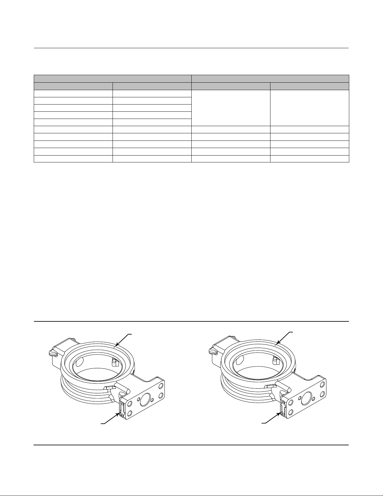
Figure 2. Flow Direction Arrow
RETAINER RING SIDE
RETAINER RING SIDE
FLOW ARROW
4
FORWARD FLOW
FLOW ARROW
REVERSE FLOW
Instruction Manual
D104709X012
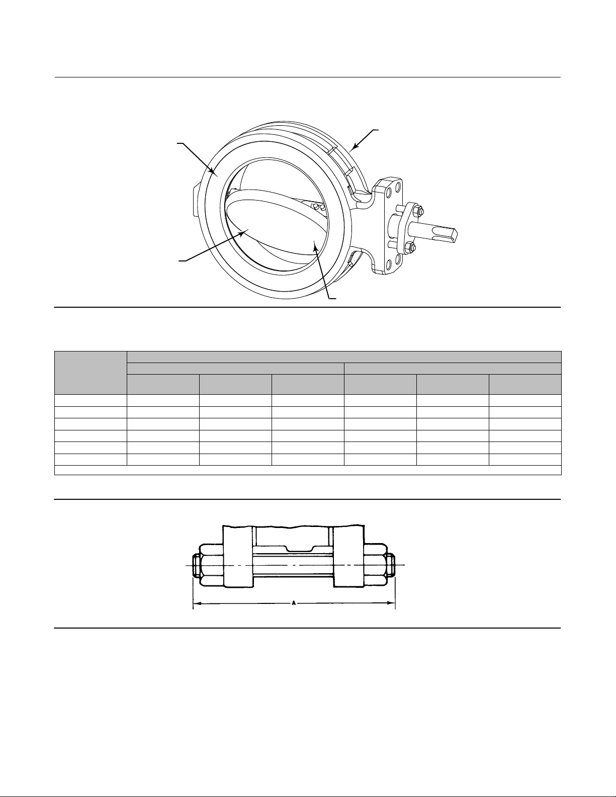
Figure 3. Flow Direction
RETAINER RING
FORWARD
FLOW
8540 Valve
September 2021
REVERSE
FLOW
FACE SIDE OF DISK
Table 5. Stud Bolt Data
VALVE SIZE, NPS
3 4 5/8‐11 5.75 8 3/4‐10 6.5
4 8 5/8‐11 6 8 3/4‐10 7
6 8 3/4‐10 6.5 12 3/4‐10 7.5
8 8 3/4‐10 7 12 7/8‐9 9
10 12 7/8‐9 8 16 1‐8 10
12 12 7/8‐9 8.5 16 1‐1/8‐8 11
1. Thread engagement in accordance with ASME B31.3.
(1)
No. of Stud Bolts
WAFER STYLE
CL150 CL300
Size Dia
Inch & Thread
A Dimension, Inch No. of Stud Bolts
Size Dia
Inch & Thread
Figure 4. Stud Bolts for Installation (also see table 5)
A3887
STUD BOLT
A Dimension, Inch
5
8540 Valve
September 2021
Instruction Manual
D104709X012
Installing the Valve in the Pipeline
WARNING
The edges of a rotating disk have a shearing effect that may result in personal injury. To help prevent such injury, stay clear
of the disk edges when rotating the disk (key 3, figure 12).
CAUTION
Damage to the disk will occur if any pipe flanges or piping connected to the valve interfere with the disk rotation path. If
the piping flange has a smaller inner diameter than what is specified for schedule 80 piping, measure carefully to be certain
the disk rotates without interference before putting the valve into operation.
CAUTION
Damage to the disk (key 3) sealing surfaces may occur if the disk is not closed when the valve is being installed or removed
from the pipeline. If necessary, use a temporary pressure source on the actuator to retain the disk in the closed position
while installing or removing the valve from the pipeline.
1. For Fail‐Open Actuators: It will be necessary to provide a temporary loading pressure to the actuator diaphragm to
move the valve disk to the closed position. Observe the above Warning when closing the valve. If a loading pressure
is required, use caution when working with the valve. If the loading pressure is disconnected, the disk will open
rapidly.
2. With the disk in the closed position, install line flange gaskets, and install the valve between the pipeline flanges.
Note
The wafer style valves use the standard size spiral wound gaskets.
Select the appropriate gaskets for the application. Gasket types made to ASME 16.5 group or a user's standards can be
used for 8540 valves depending on the service conditions and applications.
3. Install the flange studs:
Note
Lubricate line flange studs or bolts before inserting them into flanges. If necessary, provide additional support for the control valve
assembly because of its combined weight.
D Flange studs: Install two or more line flange studs into the line flanges to help hold the valve in position while
centering the valve. Carefully center the valve on the flanges to ensure disk clearance.
6
Instruction Manual
D104709X012
8540 Valve
September 2021
D Select and install two pipe line gaskets.
4. Install the remaining line flange bolting to secure the valve in the pipeline. Tighten the nuts to the line flange studs
in a crisscross pattern to ensure proper alignment of valve, gaskets, and flanges.
Packing Adjustment and Shaft Bonding
WARNING
Personal injury could result from packing leakage. Valve packing was tightened before shipment; however the packing
might require some readjustment to meet specific service conditions. Check with your process or safety engineer for any
additional measures that must be taken to protect against process media.
CAUTION
Use caution when tightening packing follower nuts because over‐tightening the nuts will accelerate wear and could
produce higher rotating friction loads on the valve stem.
D PTFE packing: tighten standard packing follower nuts only enough to prevent shaft leakage. Excessive tightening of
packing will accelerate wear and could produce higher rotating friction loads on the valve stem. If necessary, refer
to the Packing Maintenance section.
WARNING
The valve drive shaft is not necessarily grounded to the pipeline when installed. Personal injury or property damage could
result from an explosion caused by a discharge of static electricity from the valve components if the process fluid or the
atmosphere around the valve is flammable. To avoid personal injury or property damage, make sure the valve is grounded
to the pipeline before placing the valve assembly into service.
Standard PTFE packing is composed of a partially conductive carbon‐filled PTFE female adaptor with PTFE V‐ring packing.
Alternate shaft‐to‐valve body bonding is available for hazardous service areas where the standard packing is not sufficient
to bond the shaft to the valve (see the following step).
1. Attach the bonding strap assembly (key 131, figure 5) to the shaft with the clamp (key 130, figure 5), and connect
the other end of the bonding strap assembly to the valve with the cap screw (key 14, figure 5).
2. For more information, refer to the Packing Maintenance subsection below.
7

8540 Valve
September 2021
Figure 5. Optional Shaft-to-Valve Body Bonding Strap Assembly
VALVE BODY
Instruction Manual
D104709X012
ACTUATOR MOUNTING BRACKET
A
GH14001
VIEW A-A
A
Maintenance
Valve parts are subject to normal wear and must be inspected and replaced as necessary. The frequency of inspection
and replacement depends upon the severity of service conditions. Instructions are given in this section for replacing
packing, seal ring, disk, shaft, bearings, and other valve parts. Also, instructions are provided for changing valve action,
mounting, and adjusting the actuator. Refer to the actuator instruction manual for additional information for
mounting and adjusting the actuator.
WARNING
Avoid personal injury or property damage from sudden release of process pressure or bursting of parts. Before performing
any maintenance operations:
D Do not remove the actuator from the valve while the valve is still pressurized.
D Always wear protective gloves, clothing, and eyewear when performing any maintenance operations to avoid personal
injury.
D Disconnect any operating lines providing air pressure, electric power, or a control signal to the actuator. Be sure the
actuator cannot suddenly open or close the valve.
D Use bypass valves or completely shut off the process to isolate the valve from process pressure. Relieve process pressure
from both sides of the valve. Drain the process media from both sides of the valve.
D Vent the pneumatic actuator loading pressure and relieve any actuator spring precompression.
D Use lock‐out procedures to be sure that the above measures stay in effect while you work on the equipment.
D The valve packing box may contain process fluids that are pressurized, even when the valve has been removed from the
pipeline. Process fluids may spray out under pressure when removing the packing hardware or packing rings, or when
loosening the packing box pipe plug.
D Check with your process or safety engineer for any additional measures that must be taken to protect against process
media.
D It is possible to damage the valve if the actuator travel stops are not properly adjusted before stroking the valve.
8
 Loading...