

Fisher Instruction Manual: Fisher 667NS Diaphragm Actuators Size 40, 45, 70, and 80 Manuals & Guides

Instruction Manual
D102603X012
667NS Actuator
June 2018
Fisher
™
667NS Diaphragm Actuators
Size 40, 45, 70, and 80
Contents
Introduction 1.................................
Scope of Manual 1.............................
Description 1.................................
Specifications 3...............................
Educational Services 3.........................
Maximum Pressure Limitations 3..................
Installation 4..................................
Actuator Mounting 5..........................
Direct‐Acting
(Push‐Down‐to‐Close) Valves 5............
Reverse‐Acting
(Push‐Down‐to‐Open) Valves 6............
Loading Connection 8..........................
Adjustments 9.................................
Travel 9......................................
Introduction
Spring 9.....................................
Discussion of Bench Set 9...................
Adjustment Steps 10.......................
Operation 11..................................
Maintenance 11................................
Replacement of the Elastomeric Parts 12..........
Size 40, 45, and 70 Actuators 12.............
Size 80 Actuators 13.......................
Disassembly 14...............................
Size 40, 45, and 70 Actuators 14.............
Size 80 Actuators 14.......................
Assembly 15..................................
Size 40, 45, and 70 Actuators 15.............
Size 80 Actuators 16.......................
Parts Ordering 18...............................
Parts List 18...................................
Scope of Manual
This manual provides installation, maintenance, and parts list information for the Fisher 667NS actuator. Refer to
separate instruction manuals for information regarding the control valve and accessories.
Do not install, operate, or maintain 667NS actuators without being fully trained and qualified in valve, actuator, and
accessory installation, operation, and maintenance. To avoid personal injury or property damage, it is important to
carefully read, understand, and follow all the contents of this manual, including all safety cautions and warnings. If you
have any questions about these instructions, contact your Emerson sales office
proceeding.
or Local Business Partner before
Description
The 667NS actuator is a reverse‐acting, spring‐opposed diaphragm actuator that is used for operation of automatic
control valves. The 667NS actuator yoke construction and special bonnet‐to‐yoke bolting provides a high structural
resonant frequency that exceeds most nuclear service seismic requirements.
www.Fisher.com
667NS Actuator
June 2018
Instruction Manual
D102603X012
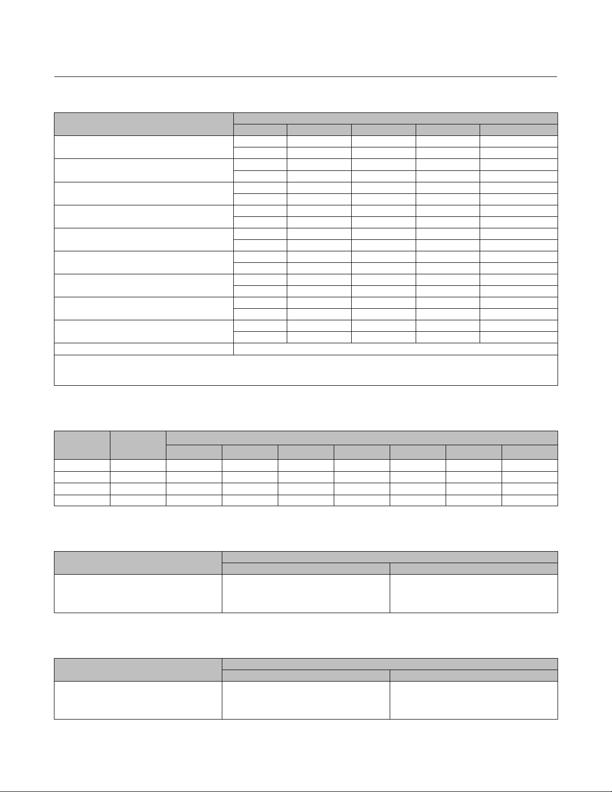
Table 1. Fisher 667NS Specifications
SPECIFICATION
2
Nominal Effective Diaphragm Area
Yoke Boss Diameters
Acceptable Valve Stem Diameters
Maximum Allowable Output Thrust
(1)
Maximum Travel
Maximum Diaphragm Pressure to Stroke
Maximum Excess Diaphragm Pressure
Maximum Casing Pressure for Actuator Sizing
Maximum Diaphragm Casing Pressure
Material Temperature Capabilities
1. See also the Specifications portion of the Introduction section. Do not exceed maximum allowable valve stem load when applying maximum allowable thrust.
2. Maximum diaphragm casing pressure must not be exceeded and must not produce a force on the actuator stem greater than the maximum allowable actuator output thrust or the maxi
mum allowable stem load.
3. The pressure and temperature limitations in this manual, and any applicable code limitation, should not be exceeded.
Actuator
(2,3)
(2,3)
(3)
(2,3)
(3)
cm
2
Inch
mm 71 71 90 5H
Inch 2‐13/16 2‐13/16 3‐9/16 5H
mm 12.7 12.7 19.1 25.4 & 31.8
Inch 1/2 1/2 3/4 1 & 1‐1/4
N 12,015 30,371 42,720 88,110
Lb 2700 6825 9600 19,800
mm 38 51 76 76
Inch 1.5 2 3 3
Bar 4.5 4.5 3.5 4.8
Psig 65 65 50 70
Bar 1.4 0.7 0.7 1.4
Psig 20 10 10 20
Bar 4.8 4.5 3.4 4.9
Psig 70 65 50 70
Bar 6.2 5.2 4.1 5.5
Psig 90 75 60 80
40 45 70 80
445 677 1419 see table 5
69 105 220 see table 5
-40 to 82_C (-40 to 180_F) with nitrile diaphragm
ACTUATOR SIZE
Table 2. Diaphragm Casing Volumes, cm3 (Inch3)
ACTUATOR
SIZE
CLEARANCE
VOLUME, cm
(INCH3)
3
11 (0.4375) 16 (0.625) 19 (0.75) 29 (1.125) 38 (1.5) 51 (2) 76 (3)
40 934 (57) 1475 (90) 1704 (104) 1852 (113) 2327 (142) 2786 (170) ‐ ‐ ‐ ‐ ‐ ‐
45 1556 (95) ‐ ‐ ‐ 2786 (170) 2999 (183) 3720 (227) 4424 (270) 5408 (330) ‐ ‐ ‐
70 3490 (213) 5244 (320) 5948 (363) 6424 (392) 7833 (478) 9242 (564) 11,110 (678) 14,879 (908)
80 4818 (294) ‐ ‐ ‐ ‐ ‐ ‐ ‐ ‐ ‐ 10,488 (640) 12,454 (760) 14,863 (907) 19,337 (1180)
TRAVEL, mm (INCH)
Table 3. Actuator Stem Assembly Bolt Torque Values
ACTUATOR SIZE
40
45
70
80
NSm LbfSFt
68
183
183
542
TORQUE
50
135
135
400
Table 4. Bonnet‐to‐Actuator Bolt Torque Values
ACTUATOR SIZE
40
45
70
80
BONNET‐ACTUATOR STUD BOLT TORQUE
NSm LbfSFt
102
102
176
292
75
75
130
215
2

Instruction Manual
D102603X012
667NS Actuator
June 2018
Table 5. Size 80 Diaphragm Area
TRAVEL AREA
mm Inch cm
0
19
29
38
51
64
76
0
0.75
1.125
1.5
2
2.5
3
2039
1903
1865
1845
1832
1800
1761
2
Inch
316
295
289
286
284
279
273
2
Specifications
Tables 1 and 2 provide specifications for the various sizes of 667NS actuators discussed in this instruction manual.
WARNING
To avoid personal injury or property damage, do not exceed pressure and temperature limits specified in table 1.
Educational Services
For information on available courses for the Fisher 667NS diaphragm actuator, as well as a variety of other products,
contact:
Emerson Automation Solutions
Educational Services - Registration
Phone: 1-641-754-3771 or 1-800-338-8158
E-mail: education@emerson.com
emerson.com/fishervalvetraining
Maximum Pressure Limitations
The casing and diaphragm of 667 actuators are pressure operated. This air pressure provides energy to compress the
spring, to stroke the actuator, and lift the diaphragm away from the valve. The following explanations describe the
maximum pressure limits for an actuator. Refer to table 1 for maximum values.
WARNING
To avoid personal injury or property damage, do not exceed pressure and temperature limits specified in table 1.
D Maximum Diaphragm Pressure to Stroke the Actuator: This is the maximum pressure that can be applied at less
than full travel of the actuator. If this stroking pressure is exceeded before the upper diaphragm plate contacts the
travel stop, damage to the stem or other parts might result.
3

667NS Actuator
June 2018
Instruction Manual
D102603X012
D Maximum Excess Diaphragm Pressure: Additional pressure may be added when the actuator is at full travel. If the
Maximum Excess Diaphragm Pressure is exceeded, damage to the diaphragm or diaphragm casing might result.
Because the actuator has traveled its specified travel, and the diaphragm head is physically stopped from movement,
the energy from any additional air pressure is transmitted to the diaphragm and diaphragm casings. The amount of air
pressure that can be added once the actuator has traveled to the stops is limited by the resultant adverse effects that
may occur. Exceeding this limiting factor could result in leakage or casing fatigue due to the deformation of the upper
diaphragm casing.
D Maximum Diaphragm Casing Pressure: If the Maximum Diaphragm Casing Pressure is exceeded, damage to the
diaphragm, diaphragm casing, or actuator might result. For some actuator sizes, the maximum casing pressure is
the sum of the maximum stroking pressure added to the maximum excess pressure. For other actuator sizes, the
value is lower than the sum of the two pressures.
Installation
The diaphragm actuator is normally shipped mounted on a valve body. Follow the valve body instructions when
installing the control valve in the pipeline.
WARNING
Always wear protective gloves, clothing, and eyewear when performing any installation operations to avoid personal
injury.
Check with your process or safety engineer for any additional measures that must be taken to protect against process
media.
If installing into an existing application, also refer to the WARNING at the beginning of the Maintenance section in this
instruction manual.
If the cover (key 84, figure 4) is not in place on the actuator, install it as shown in figure 4.
WARNING
If the control valve and actuator are installed with the actuator in any position other than vertical, the actuator may not
conform with safety‐related qualifications. Nonvertical orientation should be part of existing qualification analysis on file
at the plant site to ensure conformance with safety‐related qualifications.
The control valve assembly may be installed with any orientation; however, the actuator should not be installed in
ways that allow water to collect in the yoke and actuator spring areas.
Note
The 667NS actuator will not mount on a standard valve bonnet; it requires a style NS bonnet having eight bonnet‐to‐yoke stud
bolts.
4

Instruction Manual
D102603X012
667NS Actuator
June 2018
If the actuator and control valve body are separate, mount the 667NS actuator on the valve body by following the
procedures in the Actuator Mounting section of this manual.
Actuator Mounting
Direct‐Acting (Push‐Down‐to‐Close) Valves
Refer to figure 1.
1. Screw the stem locknuts all the way onto the valve stem. Put the travel indicator disk, not used with the size 80
actuator, on the locknuts. The concave side of the disk should face the valve.
2. Place the actuator on the valve bonnet.
3. Insert the cap screws and tighten the hex nuts (not shown), securing the actuator to the bonnet. Tighten the cap
screws to the torque shown in table 4.
4. Apply loading pressure to the actuator to retract the actuator stem fully (against the travel stop).
5. With the travel indicator scale attached to the actuator yoke, make a temporary mark on the actuator stem in line
with the top mark on the scale (the mark on the end of the scale that is marked “OPEN”). (The distance from the top
mark on the scale to the bottom mark is equal to the travel of the valve.)
Note
Before turning the spring adjuster on size 70 or 80 actuators, assemble the stem connector around the actuator stem and the
anti‐rotating lug on the yoke. Mark the actuator stem as a visual reference to verify that stem rotation does not occur. Remove the
stem connector before rechecking the bench set.
6. Refer to the actuator nameplate to determine the bench set pressure range of the actuator. Reduce actuator
loading pressure to the lower end of the bench set range. (For size 80, remove the cap screw (key 91, figure 4) and
remove the adjusting screw cover (key 84, figure 4). Rotate the spring adjustor (key 74, figure 2 for sizes 40 and 45;
key 74, figure 3 for size 70; and key 74, figure 4 for size 80) until the mark you made on the actuator stem is in line
with the bottom mark on the travel indicator scale. (Replace the size 80 adjusting screw cover and cap screw when
you have completed the adjustments.)
7. Increase actuator loading pressure to the upper end of the bench range and check to be sure that the mark on the
actuator stem is in line with the top mark on the travel indicator scale.
If the marks are in line, the actuator is properly bench set.
If the marks are not in line, the spring is not correct for the specified bench set. It is necessary to use a different spring
or a different bench set.
8. Reduce actuator loading pressure until the mark on the actuator stem is in line with the bottom mark on the travel
indicator scale.
CAUTION
Do not clamp just the tip of either the valve stem or the actuator stem in the stem connector. Incomplete engagement of
the valve stem and/or actuator stem in the stem connector might result in stripped threads or improper operation. Be sure
that the length of each stem clamped in the stem connector is equal to or greater than the diameter of that stem.
5

667NS Actuator
June 2018
Instruction Manual
D102603X012
9. Push the valve stem firmly against its seat, and be sure that it remains firmly against the seat. Clamp the actuator
stem and valve stem between the two stem connector halves.
If necessary, increase actuator loading pressure slightly to allow the valve stem, actuator stem, and stem connector
threads to match.
Insert and tighten the stem connector cap screws.
WARNING
To avoid personal injury due to the sudden, uncontrolled movement of parts, do not loosen the cap screws when the stem
connector has spring or loading pressure force applied to it.
10. Raise the travel indicator disk (sizes 40 through 70 only) to the stem connector. For all sizes, thread the stem
locknuts against the stem connector.
11. Remove all actuator loading pressure. Move the travel indicator scale so that the indicator disk (or pointer) is in
line with the bottom mark of the travel indicator scale.
12. Check the valve travel to be sure that the valve travels fully with no overtravel.
Reverse‐Acting (Push‐Down‐to‐Open) Valves
Refer to figure 1.
1. Screw the stem locknuts all the way onto the valve stem. Put the travel indicator disk, not used with the size 80
actuator, on the locknuts. The concave side of the disk should face the valve.
2. Place the actuator on the valve bonnet.
3. Insert the cap screws and tighten the hex nuts (not shown), securing the actuator to the bonnet. Tighten the cap
screws to the torque in table 4.
Note
Before turning the spring adjuster on size 70 or 80 actuators, assemble the stem connector around the actuator stem and the
anti‐rotating lug on the yoke. Mark the actuator stem as a visual reference to verify that stem rotation does not occur. Remove the
stem connector before rechecking the bench set.
4. (For size 80, remove the cap screw (key 91, figure 4) and remove the adjusting screw cover (key 84, figure 4).
Rotate the spring adjustor (key 74, figure 2 for sizes 40 and 45; key 74, figure 4 for size 70; and key 74, figure 4 for
size 80) to position the actuator stem at its fully extended position.
5. With the travel indicator scale attached to the actuator yoke, make a temporary mark on the actuator stem in line
with the bottom mark on the scale (the mark on the end of the scale that is marked “OPEN”). (The distance from the
bottom mark on the scale to the top mark is equal to the travel of the valve.)
6. Refer to the actuator nameplate to determine the bench set pressure range of the actuator. Apply an actuator
loading pressure to the actuator equal to the lower end of the bench set range and rotate the spring adjustor until
the mark you made on the actuator stem is in line with the bottom mark on the travel indicator scale. (Replace the
size 80 adjusting screw cover and cap screw when you have completed the adjustments.)
6

Instruction Manual
D102603X012
Figure 1. Schematic and Stem Connection Details for Fisher 667NS
AIR
LIFTS
A3833‐A
SPRING
PUSHES
DOWN
SCHEMATIC
YOKE
TRAVEL
INDICATOR
STEM
LOCKNUTS
55A9191‐H
SIZES 40 AND 45
667NS Actuator
June 2018
SPRING
ADJUSTOR
STEM
CONNECTOR
TRAVEL
INDICATOR
DISK
VALVE
STEM
VENT
DIAPHRAGM
CASING
YOKE
ACTUATOR
VALVE
STUDS
AND NUTS
FISHER
DBQ-NS
VALVE
A5958/MM1
C0762‐1
YOKE
TRAVEL
INDICATOR
STEM
LOCKNUTS
55A9193‐F
TRAVEL
INDICATOR
YOKE
STEM
LOCKNUTS
56A1032‐D
SPRING
ADJUSTOR
TRAVEL
INDICATOR
DISK
VALVE
STEM
SIZE 70
TRAVEL
INDICATOR
POINTER
STEM
CONNECTOR
VALVE
STEM
SIZE 80
STEM CONNECTION
DETAILS
7

667NS Actuator
June 2018
7. Increase actuator loading pressure to the upper end of the bench range and check to be sure that the mark on the
actuator stem is in line with the top mark on the travel indicator scale.
If the marks are in line, the actuator is properly bench set.
If the marks are not in line, the spring is not correct for the specified bench set. It is necessary to use a different spring
or a different bench set.
Instruction Manual
D102603X012
CAUTION
Do not clamp just the tip of either the valve stem or the actuator stem in the stem connector. Incomplete engagement of
the valve stem and/or actuator stem in the stem connector might result in stripped threads or improper operation. Be sure
that the length of each stem clamped in the stem connector is equal to or greater than the diameter of that stem.
8. Pull the valve stem firmly against its seat, and be sure that it remains firmly against the seat. Clamp the actuator
stem and valve stem between the two stem connector halves.
If necessary, decrease actuator loading pressure slightly to allow the valve stem, actuator stem, and stem connector
threads to match.
Insert and tighten the stem connector cap screws.
WARNING
To avoid personal injury due to the sudden uncontrolled movement of parts, do not loosen the cap screws when the stem
connector has spring or loading pressure force applied to it.
9. Raise the travel indicator disk to the stem connector (sizes 40 through 70 only). For all sizes, thread the stem
locknuts against the stem connector.
10. Remove all actuator loading pressure. Move the travel indicator scale so that the indicator disk (or pointer) is in line
with the bottom mark of the travel indicator scale.
11. Check the valve travel to be sure that the valve travels fully with no overtravel.
Loading Connection
1. Connect the loading pressure piping to the NPT internal connection in the top of the actuator yoke.
2. For size 70 actuators, remove the 1/4‐inch bushing in the 1/2 NPT internal connection to increase connection size, if
necessary. Use either piping or tubing.
3. Keep the length of tubing or piping as short as possible to avoid transmission lag in the control signal. If an
accessory (such as a volume booster or valve positioner) is used, be sure that the accessory is properly connected to
the actuator. Refer to the positioner instruction manual if necessary.
4. Cycle the actuator several times to check that the valve stem travel is correct and that the travel occurs when the
correct pressure range is applied to the diaphragm.
5. If valve stem travel is incorrect, refer to the Travel procedure in the Adjustments section.
6. If the pressure range is incorrect, refer to the Spring procedure in the Adjustments section.
8
 Loading...