

Fisher Instruction Manual: Fisher 657C Diaphragm Actuator Sizes 40i, 46i, and 60i Manuals & Guides

Instruction Manual
D104496X012
Fisher™ 657C Diaphragm Actuator
Sizes 40i, 46i, and 60i
657C Actuator (40i, 46i, and 60i)
November 2019
Contents
Introduction 1.................................
Scope of Manual 1.............................
Description 2.................................
Specifications 2...............................
Educational Services 3.........................
Installation 3..................................
Mounting the Actuator on the Desuperheater 4....
Discussion of Bench Set 7.......................
Spring Verification 7...........................
Installing the Stem Connector Assembly 9.........
Friction Discussion 10..........................
Deadband Measurement 11.....................
Loading Connection 11.........................
Maintenance 12................................
Actuator Maintenance 12.......................
Top‐Mounted Handwheel Assembly 14...........
Casing‐Mounted Adjustable Travel Stops 16.......
Parts Ordering 18...............................
Parts Kits 18...................................
Kits for Top‐Mounted Handwheels 18.............
Kits for Adjustable Down Travel Stops 18..........
Parts List 19...................................
Actuator Assembly (figures 7, 8, and 9) 19.........
Figure 1. Fisher 657C Actuator
Introduction
Scope of Manual
This instruction manual provides information on installation, adjustment, maintenance, and parts ordering for the
Fisher 657C actuator in sizes 40i, 46i, and 60i. Refer to separate instruction manuals for information about the
desuperheater positioner and other accessories used with these actuators.
Do not install, operate, or maintain a 657C actuator without being fully trained and qualified in Yarway
desuperheater, actuator, and accessory installation, operation, and maintenance. To avoid personal injury or property
damage, it is important to carefully read, understand, and follow all the contents of this manual, including all safety
cautions and warnings. If you have any questions about these instructions, contact your Emerson sales office
proceeding.
www.Fisher.com
™
before
657C Actuator (40i, 46i, and 60i)
2
2
November 2019
Instruction Manual
D104496X012
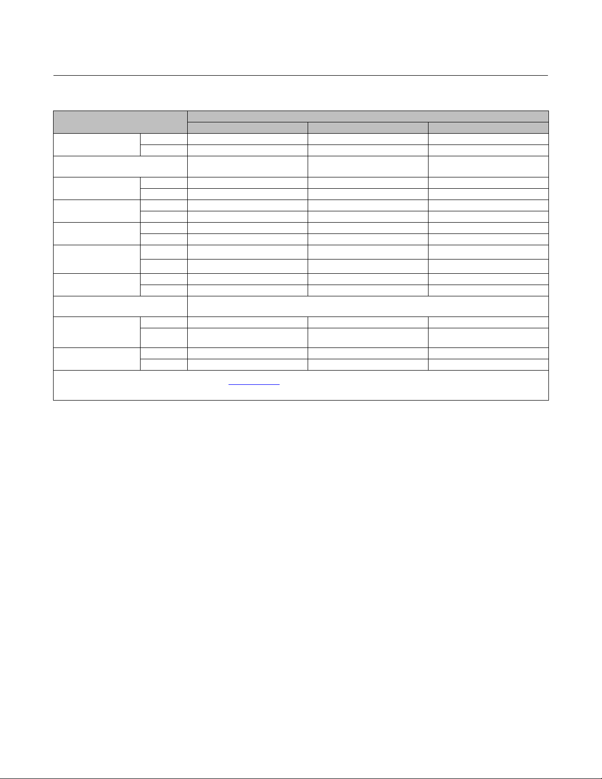
Table 1. Specifications
SPECIFICATION
Nominal Effective Area
Acceptable Desuperheater
Stem Diameters
Yoke Boss Diameters
Maximum Allowable
Output Thrust
Maximum Travel
Maximum Casing
Pressure for
Actuator Sizing
Maximum Diaphragm
Casing Pressure
Operating Temperature Range
Pressure Connections
(internal)
Approximate Weights
1. Normal operating diaphragm pressure must not exceed maximum diaphragm casing pressure and must not produce a force on the actuator stem greater than the maximum allowable
output thrust or the maximum allowable stem load. Contact your Emerson sales office
2. This maximum casing pressure is not to be used for normal operating pressure. Its purpose is to allow for typical regulator supply settings and/or relief valve tolerances.
3. Actuator travel may be less than the value listed after connecting the actuator to the valve.
(1)
(3)
(1)
(1)(2)
cm
Inch
mm 71 71 91
Inches 2‐13/16 2‐13/16 3‐9/16
N 12010 30246 30246
Lb 2700 6800 6800
mm 89 105 105
Inches 3-1/2 4-1/8 4-1/8
Bar 4.5 2.8 2.8
Psig 65 40 40
Bar 5.2 3.4 3.4
Psig 75 50 50
1/4 NPT X X X
1/2 NPT
(optional)
kg 34 66 72
Lb 75 146 160
40i 46i 60i
445 1006 1006
69 156 156
12 mm or 1/2 inch 12 mm or 1/2 inch 16 mm
Nitrile Elastomers: -40 to 82_C (-40 to 180_F),
Silicone Elastomers: -54 to 149_C (-65 to 300_F)
X X X
for more information concerning maximum allowable stem load.
ACTUATOR SIZE
Description
The Fisher 657C actuators (figure 1) are long stroke, spring opposed, direct‐acting diaphragm actuators. They are
designed for Yarway desuperheater line of products (AT-38/48, AT-37/47, AT-18/28, and 4300 Templow
suitable for push‐down‐to‐open (PDTO) applications and are available in sizes 40i, 46i and 60i to provide 89 mm (3.5
inch), or 105 mm (4.125 inch) maximum actuator travel.
A 657C actuator can be equipped with a top-mounted handwheel assembly. Adjustable casing-mounted down travel
stop is also available for this actuator.
™
). They are
Specifications
Refer to table 1 for Specifications of the 657C actuator. See the actuator nameplate for specific information about your
actuator.
2
Instruction Manual
D104496X012
657C Actuator (40i, 46i, and 60i)
November 2019
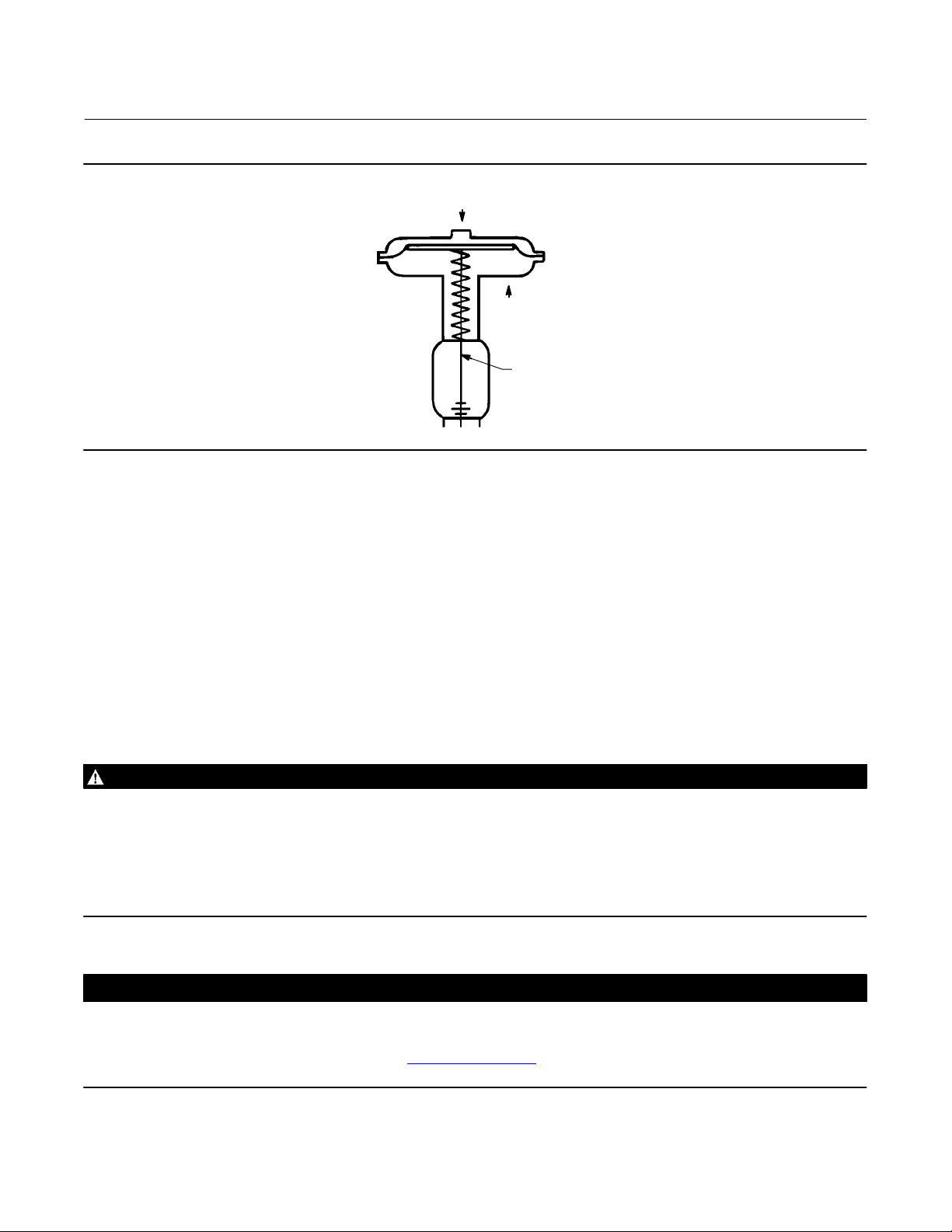
Figure 2. Schematic of Fisher 657C Actuator
AIR PUSHES
STEM DOWN
SPRING LIFTS
STEM UP
STEM
AF3833‐A
A0792‐2
Educational Services
For information on available courses for Fisher 657C diaphragm actuators, as well as a variety of other products,
contact:
Emerson Automation Solutions
Educational Services - Registration
Phone: 1-641-754-3771 or 1-800-338-8158
E-mail: education@emerson.com
emerson.com/fishervalvetraining
Installation
Key number locations are shown in figure 7 unless otherwise indicated. Also, refer to figure 3 for location of parts.
WARNING
Always wear protective gloves, clothing, and eyewear when performing any installation operations to avoid personal
injury.
Check with your process or safety engineer for any additional measures that must be taken to protect against process
media.
If installing into an existing application, also refer to the WARNING at the beginning of the Maintenance section in this
instruction manual.
CAUTION
To avoid parts damage, do not use an operating pressure that exceeds the Maximum Diaphragm Casing Pressure (table 1)
or produces a force on the actuator stem greater than the Maximum Allowable Output Thrust (table 1) or the maximum
allowable desuperheater stem load. (Contact your Emerson sales office
desuperheater stem load.)
with questions concerning maximum allowable
3

657C Actuator (40i, 46i, and 60i)
November 2019
D Desuperheater/Actuator Assembly: If the actuator and desuperheater are shipped together as an assembly, it has
been adjusted at the factory, and may be installed in the pipeline. After installing the desuperheater in the pipeline,
refer to the Loading Connection procedures.
D Actuator Mounting: If the actuator is shipped separately or the actuator has been removed from the desuperheater,
the actuator should be mounted to the desuperheater before placing the desuperheater in the pipeline when
practical. Refer to the actuator mounting procedures before placing the desuperheater in service. You may perform
the Bench Set Spring Adjustment procedures in this section to confirm the adjustment has not changed since it was
shipped from the factory. Support actuator when in any other position than vertical.
D Positioner: If a positioner is installed, or is to be installed on the actuator, refer to the positioner instruction manual
for installation. During the adjustment procedures, it will be necessary to provide a temporary loading pressure to
the actuator diaphragm.
Instruction Manual
D104496X012
Mounting the Actuator on the Desuperheater
The 657C actuator spring loading pushes the actuator stem up towards the actuator diaphragm (see figure 2). This
spring action moves the stem away from the desuperheater while installing the actuator.
CAUTION
If the valve stem is allowed to remain in the up position (towards the actuator) during mounting, it can interfere with the
actuator mounting, possibly damage valve stem threads or bend the valve stem. Be sure the valve stem is pushed down
(into the valve body), away from the actuator while mounting.
Provide a temporary method of applying diaphragm loading pressure to the diaphragm to extend the actuator stem
during bench set spring adjustments. Provide a regulator to adjust the actuator stem during bench set spring
adjustments and a shut-off valve to isolate and prevent unwanted movement.
1. Provide a vise or some other method of supporting the desuperheater and the weight of the actuator during
assembly. Push the desuperheater stem down away from the actuator while mounting the actuator.
2. Screw the stem locknuts all the way onto the desuperheater stem. With the concave side of the travel indicator disk
(key 14, figure 7) facing the desuperheater, install the travel indicator disk on the desuperheater stem.
3. Lift or hoist the actuator onto the desuperheater yoke mounting boss:
a. Screw the yoke locknut onto the desuperheater yoke mounting boss and tighten the locknut. (Note: On small
size actuators, it may be necessary to remove the indicator disk and re‐install it while lowering the actuator on to
the desuperheater because the disk will not go through the actuator yoke opening.)
4. Do not connect the actuator stem to the desuperheater stem at this time. Whenever the actuator is installed on the
desuperheater , it is recommended to perform the Bench Set Spring Adjustment procedure to verify that the
actuator is still adjusted correctly.
4
Instruction Manual
D104496X012
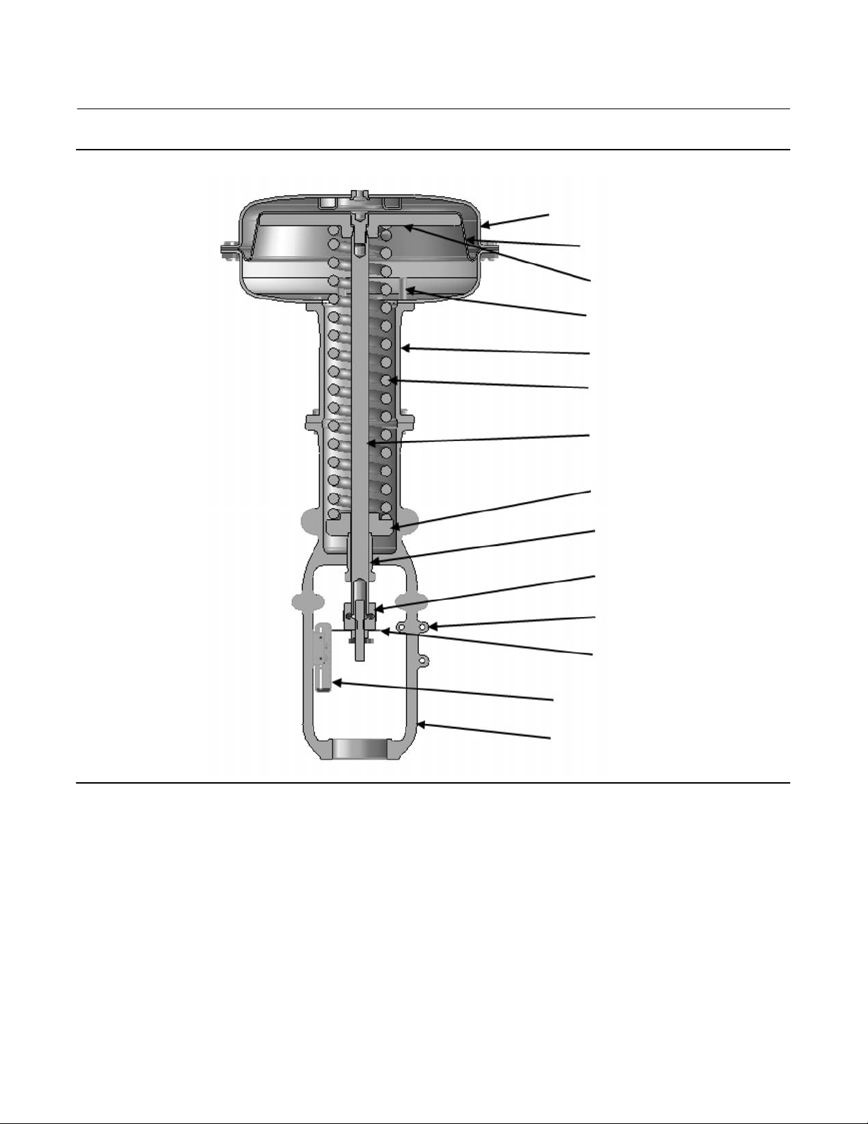
Figure 3. Actuator Components for Size 40i, 46i, and 60i Actuators
657C Actuator (40i, 46i, and 60i)
November 2019
DIAPHRAGM CASINGS
DIAPHRAGM
DIAPHRAGM PLATE
TRAVEL STOP
YOKE EXTENSION
ACTUATOR SPRING
ACTUATOR STEM
SPRING SEAT
SPRING ADJUSTOR
STEM CONNECTOR
INTEGRAL INSTRUMENT PAD
TRAVEL INDICATOR
INDICATOR SCALE
YOKE
5
657C Actuator (40i, 46i, and 60i)
November 2019
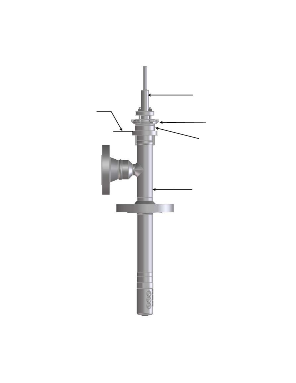
Figure 4. Construction of Yarway Desuperheater
MATCH LINE FOR
ACTUATOR
Instruction Manual
D104496X012
DESUPERHEATER STEM
YOKE LOCK NUT
YOKE BOSS DIAMETER
YARWAY DESUPERHEATER
6
Instruction Manual
D104496X012
657C Actuator (40i, 46i, and 60i)
November 2019
Discussion of Bench Set
The bench set pressure values are used to adjust the initial compression of the actuator spring with the
desuperheater‐actuator assembly “on the bench.” The correct initial compression is important for the proper
functioning of the desuperheater‐actuator assembly when it is put into service and the proper actuator diaphragm
operating pressure is applied.
The bench set values are established with the assumption that there is no packing friction. When attempting to adjust
the spring in the field, it is very difficult to ensure that there is no friction being applied by “loose” packing.
Accurate adjustment to the bench set range can be made during the actuator mounting process by making the
adjustment before the actuator is connected to the desuperheater (see the Spring Verification procedure).
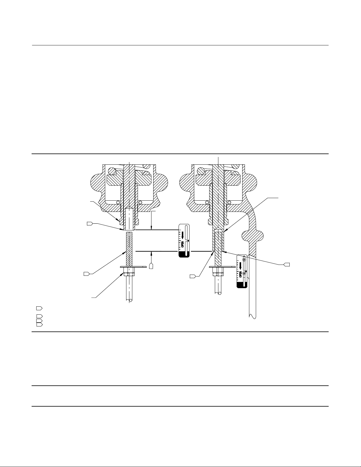
Figure 5. Bench Set Adjustment
SPRING ADJUSTER
RATED VALVE
LOWER BENCH SET
LOADING PRESSURE
UPPER BENCH SET
PRESSURE MARK
VALVE STEM
NOTES:
1
THE LOWER PSIG LOADING PRESSURE (MARKED ON NAMEPLATE) WHERE THE FIRST MOVEMENT OF
ACTUATOR STEM IS DETECTED.
2
THE UPPER PSIG LOADING PRESSURE EXTENDS ACTUATOR STEM.
3
MARK THIS POINT WITH TAPE OR A MARKER.
4
MEASURE DISTANCE OF TRAVEL. IT SHOULD EQUAL THE TRAVEL SPAN SHOWN ON THE NAMEPLATE.
1
3
TRAVEL MEASURE
4
MARK VALVE
STEM HERE
Spring Verification
ACTUATOR STEM
UPPER BENCH
SET LOADING
2
PRESSURE
3
Ensure that the actuator stem is at the top of its travel as shown in figure 5 and not connected to the desuperheater.
Note
Some spring compression is required to move the diaphragm to the top of its travel.
The steps provided are for push-down-to-open desuperheaters.
7

657C Actuator (40i, 46i, and 60i)
November 2019
Instruction Manual
D104496X012
WARNING
When moving the actuator stem with diaphragm loading pressure, use caution to keep hands and tools out of the actuator
stem travel path. Personal injury and/or property damage is possible if something is caught between the actuator stem and
other desuperheater assembly parts.
Also, provide a certified pressure gauge suitable to accurately read the diaphragm pressure from 0 through 0.3 bar (5
psig) above the upper operating range pressure marked on the nameplate. Apply loading pressure to the diaphragm.
CAUTION
Stroke the actuator a few times to ensure that the pressure gauge is working correctly, and that the actuator is functioning
properly. To prevent actuator damage, it is important to ensure that the actuator stem is stroking smoothly and not
exhibiting binding or excessive friction. Binding or excessive friction could be an indicator of incorrect assembly or
damaged parts.
1. If not already accomplished, provide a regulator to apply an adjustable loading pressure to the actuator during
bench set adjustments and a shut-off valve to isolate and prevent the unwanted movement.
2. Set the diaphragm loading pressure at 0 bar (0 psig). Then, slowly raise the pressure towards the lower bench set
pressure, as indicated on the nameplate, while checking for the first linear movement of the actuator stem. The
actuator stem should show movement at the lower bench set pressure. If movement occurs before or after the
lower pressure is reached, adjust the spring adjuster (see figure 5) into or out of the yoke until the actuator stem's
movement is first detected at the lower bench set pressure.
3. Be sure the spring adjuster is adjusted to meet the requirements of step 2 above.
4. Apply the upper bench set pressure, as indicated on the nameplate. This pressure extends the actuator stem down
toward the desuperheater. At the end of the actuator stem, use a marker or a piece of tape to mark the
desuperheater stem (see figure 5).
Note
The actuator stem may slide over the desuperheater stem as shown in figure 5. If the actuator stem does not pass over the
desuperheater stem, provide a method to mark this point of stem travel.
5. Slowly decrease the diaphragm loading pressure to the lower bench set pressure, as indicated on the nameplate.
6. Measure the distance between the marker or tape on the desuperheater stem to the end of the actuator stem. The
distance should match the rated travel indicated on the nameplate.
7. If the measured travel matches the nameplate travel, bench set is complete. Proceed to the Installing the Stem
Connector Assembly subsection.
8. If the measured travel is not exact, consider the spring free-length and spring rate tolerances may produce a slightly
different bench set than specified. Contact your Emerson sales office
8
for assistance.
 Loading...