

Fisher Instruction Manual: Fisher 1051 and 1052 Size 33 Diaphragm Rotary Actuators Manuals & Guides
Instruction Manual
D101322X012
Fisher™ 1051 and 1052 Size 33
Diaphragm Rotary Actuators
1051 and 1052 Size 33 Actuators
February 2019
Contents
Introduction 1.................................
Scope of Manual 1.............................
Description 2.................................
Specifications 3...............................
Installation 3..................................
Actuator Mounting and Changing Actuator
Mounting 5................................
F and G Mounting Adaptations 5.............
H Mounting Adaptation 7...................
J Mounting Adaptation 8....................
1052 Spring Compression Adjustment 10.........
Initial Compression 10......................
Stroking Range 11.........................
Maintenance 11................................
Mounting Adaptations 12......................
Replacing Diaphragm 12.......................
Replacing Diaphragm Plate, Diaphragm Rod,
Spring, and Spring Seat 13....................
Changing Or Replacing Actuator Lever 16.........
Proximity Switches, Lever‐Operated Switches,
and Positioner 18...........................
Installing the Cam 18......................
Installing Proximity Switches 19..............
Switches Indicating Bottom of Stroke 19..
Switches Indicating Top of Stroke 19......
Installing Lever‐Operated Switch 19..........
Installing the Push Rod 20................
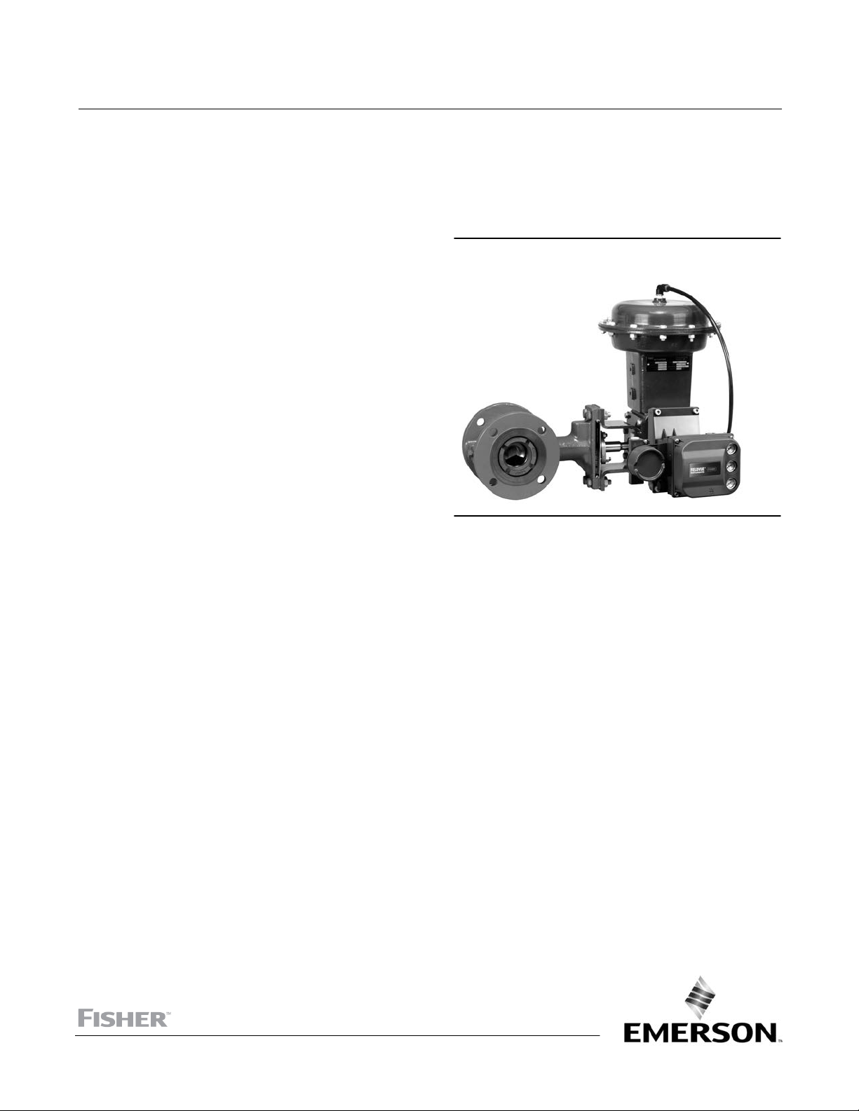
Figure 1. Fisher 1052 Actuator with CV500 Valve and
FIELDVUE™ DVC6200 Digital Valve Controller
W8192‐2
Mounting Lever‐Operated Switch and
Adjustment 20..........................
Positioner Mounting 20........................
Top‐Mounted Handwheel 20....................
Locking Mechanism 21.........................
Parts Ordering 23...............................
Parts Kits 23...................................
Parts List 23...................................
Introduction
Scope of Manual
This instruction manual includes installation, adjustment, operation, maintenance, and parts information for the
Fisher 1051 and 1052 Size 33 diaphragm rotary actuators (figure 1). Mounting adaptations F, G, H, and J are included
in this manual. Instructions for the control valve, positioner, manual actuator, and other accessories are included in
separate manuals.
www.Fisher.com

1051 and 1052 Size 33 Actuators
February 2019
Table 1. Specifications
Instruction Manual
D101322X012
Available Configuration
1051: For on‐off service without a positioner or for
throttling service with a positioner
1052: For on‐off service without a positioner or for
throttling service with or without a positioner
Standard Diaphragm Pressure Ranges
J 0 to 1.2 bar (0 to 18 psig), J 0 to 2.3 bar (0 to 33
psig), J 0 to 2.8 bar (0 to 40 psig), and J 0 to 3.8 bar
(0 to 55 psig)
Maximum Diaphragm Sizing Pressure
(1, 2)
3.8 bar (55 psig)
Maximum Diaphragm Casing Pressure
(1, 7)
4.5 bar (65 psig)
Maximum Valve Shaft Rotation
J 90 degrees (adjustable through 60 degrees with
integral travel stops)
Acceptable Valve Shaft Diameters, mm (Inches)
F and G mounting: J 12.7 (1/2), J 15.9 (5/8), or J
19.1 (3/4)
H mounting: varies—uses 22.2 mm (7/8 inch) output
shaft with two flats
J mounting: J 9.5 (3/8), J 12.7 (1/2), or 15.9 (5/8)
of supply piping. If stroking time is critical, consult
your Emerson Automation Solutions sales office.
Diaphragm Casing Displacement
Clearance Volume
Casing Volume
(3)
: 623 cm3 (38 cubic inches)
(4)
90 Degree Rotation: 2390 cm3 (146 cubic inches)
60 Degree Rotation: 1890 cm
Material Temperature Capabilities
NBR (nitrile) Diaphragm or O‐rings
3
(115 cubic inches)
(1)
(5)
:
-40 to 82_C (-40 to 180_F)
VMQ (silicone) Diaphragm:
-40 to 149_C (-40 to 300_F)
POM (polyoxymethylene) Push Rods and Guides
(used with lever‐operated switches):
-40 to 82_C
(6)
(-40 to 180_F)
Travel Indication
Graduated disk and pointer
Pressure Connections
Standard: 1/4 NPT internal
Optional: J 1/2 or J 3/4 NPT internal
Mounting Positions
See figure 2
Stroking Time
Dependent of actuator size, rotation, spring rate,
initial spring compression, supply pressure, and size
1. The pressure/temperature limits in this manual and any applicable standard or code limitation for valve should not be exceeded.
2. Use this value to determine the maximum torque output allowed.
3. Volume when the diaphragm is in the up position.
4. Includes clearance volume.
5. NBR (nitrile) O‐rings are used in the optional top‐mounted handwheel and in the optional up travel stop assembly.
6. For higher temperature ratings, contact your Emerson sales office.
7. This maximum casing pressure is not to be used for normal operating pressure. Its purpose is to allow for typical regulator supply settings and/or relief valve tolerances.
Approximate Weights
1051: 20 kg (45 pounds)
1052: 21 kg (46 pounds)
Do not install, operate, or maintain a 1051 or 1052 actuator without being fully trained and qualified in valve, actuator,
and accessory installation, operation, and maintenance. To avoid personal injury or property damage, it is important
to carefully read, understand, and follow all the contents of this manual, including all safety cautions and warnings. If
you have any questions about these instructions, contact your Emerson sales office
before proceeding.
Description
1051 and 1052 Size 33 spring‐and‐diaphragm actuators are used on rotary‐shaft valve bodies for throttling or on‐off
applications. The 1051 may be used for on‐off service without a positioner or for throttling service with a positioner.
The 1052 uses an adjustable spring seat to control spring compression. It may be used for on‐off service without a
positioner, or it may be used for throttling service with or without a positioner, depending on service conditions.
2
Instruction Manual
D101322X012
1051 and 1052 Size 33 Actuators
February 2019
A top‐mounted handwheel may be mounted for infrequent service as a manual override. A manual actuator is
recommended for routine and repeated manual operation. Externally adjustable travel stops are used to limit the
degree of rotation at both ends of the actuator stroke. Provisions are included for integral mounting of optional
magnetic proximity switches. Lever‐operated, mechanical switches are also available.
The lever for the 1051 and 1052 size 33 actuator is supported by bushings. The lever may be changed to
accommodate valve bodies with different size valve shafts and different mounting adaptations. Levers and accessories
are available for mounting valve bodies and equipment with the following mounting adaptations:
F and G mounting adaptations (figures 9 and 10) are for use with Fisher splined‐shaft rotary valve bodies with 12.7,
15.9, and 19.1 mm (1/2, 5/8, and 3/4 inch) valve shaft diameters. A stub shaft is available for installation on the end of
the lever opposite the valve body for use as a wrench‐operated extension (for emergency override) or as a means of
connecting a manual actuator (see figure 14).
H mounting (figure 11) is for use with non‐Fisher products and user‐provided mounting brackets and shaft couplings.
It includes a mounting surface with threaded holes for attaching the user‐provided mounting bracket. A 22.2 mm (7/8
inch) stub shaft with flats is pinned to the lever and is used to couple the actuator to the operated equipment. A
second stub shaft may be installed on the opposite end of the lever for use as a wrench‐operated extension (for
emergency override) or as a means for connecting a manual actuator (see figure 14). Stub shafts are available in
standard and reverse constructions (see figure 12) to provide proper operation with the mounting position and
actuator action desired (see figure 2).
J mounting (figure 13) permits use of the actuator with Fisher keyed‐shaft valve bodies and other keyed‐shaft
equipment with 9.5, 12.7, and 15.9 mm (3/8, 1/2, and 5/8 inch) shaft diameters. A stub shaft is pinned to the lever and
a valve shaft coupling is pinned to the stub shaft. The coupling has multiple keyways (see figure 4) to accommodate
mounting in the desired position. A second stub shaft may be installed on the opposite end of the lever for use as a
wrench‐operated extension (for emergency override) or as a means for connecting a manual actuator (see figure 14).
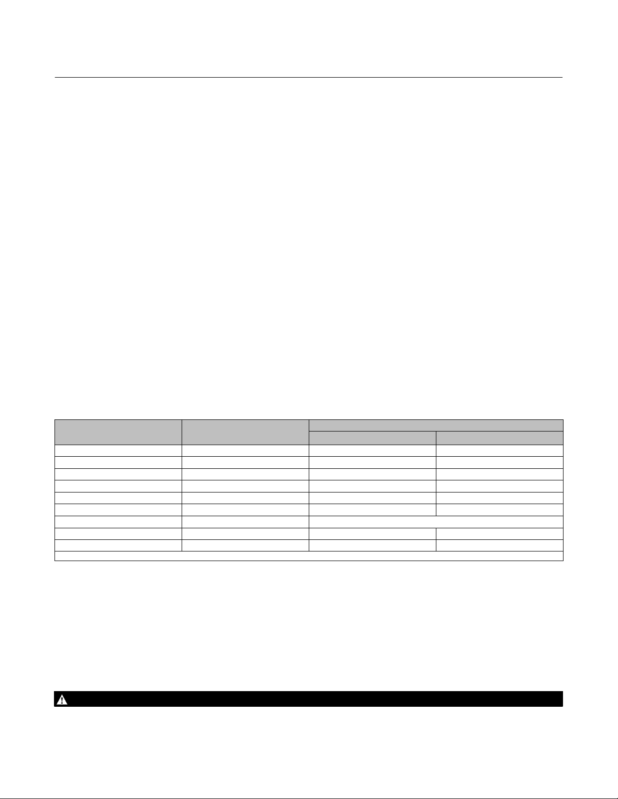
Table 2. Bolting Torque Requirements
DESCRIPTION KEY NUMBER BOLT SIZE
Diaphragm Casing 5 3/8‐24 27 20
Travel Stop 8 7/16‐14 27 20
Diaphragm to rod 9 3/8‐24 54 40
Rod end to lever 18 3/8‐16 54 40
Housing to yoke 23 5/16‐18 41 30
Housing to cover 34 5/16‐18 41 30
Yoke to valve 71 3/8‐16 (See appropriate valve instruction manual)
Clamped lever 28 3/8‐16 54 40
Switch Nut 78 3/8‐16 27 20
1. Exceeding any torque requirements could damage the actuator and impair safe operation.
(1)
TORQUE
NSm LbfSft
Specifications
Specifications are shown in table 1 for 1051 and 1052 size 33 actuators. Some specifications for a given actuator as it
originally comes from the factory are stamped on a metal nameplate attached to the actuator.
Installation
WARNING
Always wear protective gloves, clothing, and eyewear when performing any installation operations.
3
1051 and 1052 Size 33 Actuators
February 2019
Instruction Manual
D101322X012
Check with your process or safety engineer for any other hazards that may be present from exposure to process media.
If installing into an existing application, also refer to the WARNING at the beginning of the Maintenance section in this
instruction manual.
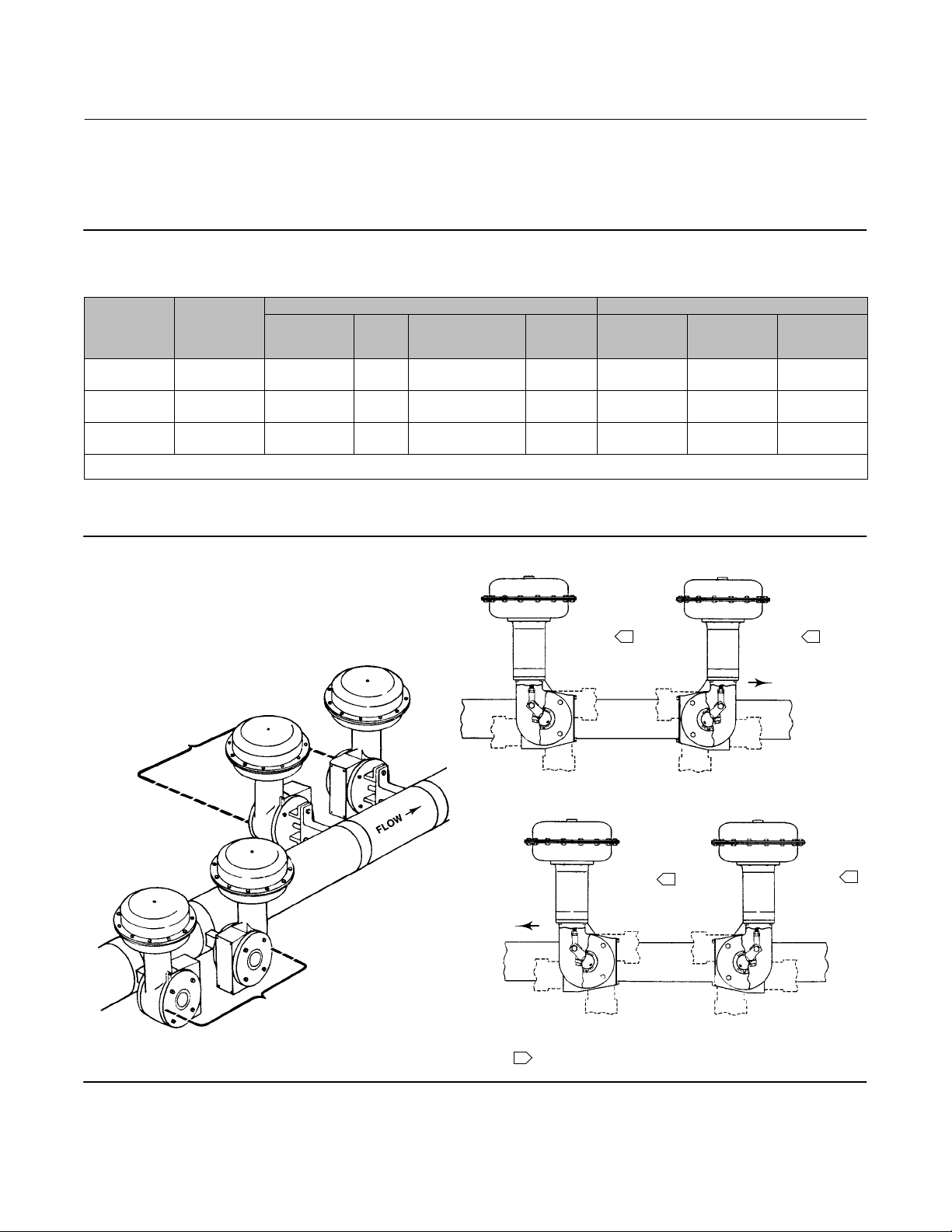
VALVE SERIES OR DESIGN VALVE SERIES OR DESIGN
MOUNTING ACTION
Right‐Hand
Left‐Hand
Left‐Hand
(Optional)
1. PDTC—Push‐down‐to‐close, and PDTO—Push‐down‐to‐open.
2. A left hand ball will be required for the NPS 3 through 12 Series B and the NPS 14 to 20, with or without attenuator.
(2)
(1)
PDTC
PDTO
PDTC
PDTO
PDTC
PDTO
BALL/PLUG
ROTATION TO
CLOSE
CCW
CCW
CCW
CCW
CW
CW
V250 V150, V200 & V300
A
B
NA
NA
NA
NA
A
B
D
C
C
D
CV500
V500
A
B
D
C
NA
NA
DISK/BALL
ROTATION TO
CLOSE
CW
CW
CW
CW
NA
NA
V250
NA
NA
C
D
NA
NA
8510B, 8532,
8560
& 9500
B
A
C
D
NA
NA
Figure 2. Mounting Styles and Positions for Fisher 1051 and 1052 Actuators
STYLE A
POSITION 1
STYLE D
STYLE C
43A6505‐A
A1584‐3
LEFT‐HAND
MOUNTING
STYLE B
STYLE A
RIGHT‐HAND
MOUNTING
4
3
STYLE D
FLOW
4
NOTES:
1
(SHOWN IN DOTTED LINES) ARE ALTERNATIVES.
STYLE B
1
2
4
POSITION 1
2
3
RIGHT‐HAND MOUNTING
STYLE C
POSITION 1
3
1
2
4
3
LEFT‐HAND MOUNTING
POSITION 1 IS STANDARD; POSITIONS 2 THROUGH 4
1
FLOW
POSITION 1
2
1
4

Instruction Manual
D101322X012
1051 and 1052 Size 33 Actuators
February 2019
CAUTION
To avoid parts damage, do not use an operating pressure that exceeds the Maximum Diaphragm Casing Pressure (table 1)
or produces a torque greater than the Maximum Allowable Valve Shaft Torque (see Catalog 14). Use pressure‐limiting or
pressure‐relieving devices to prevent the diaphragm casing pressure from exceeding its limit.
The actuator, as it comes from the factory, is normally mounted on a valve body. Follow the procedures given in the
valve instruction manual when installing the control valve in the pipeline.
If a positioner is ordered with the actuator, the pressure connection to the actuator is normally made at the factory. If
it is necessary to make this connection, run either 1/4 inch pipe or 3/8 inch tubing (for standard diaphragm case
fittings) between the pressure connection and the instrument. Keep the length of tubing or pipe as short as possible to
avoid transmission lag in the control signal.
When the control valve is completely installed and connected to the controlling instrument, check to make sure that
the action is correct (air‐to‐open or air‐to‐close) and that the controlling instrument is properly configured for the
desired action. For successful operation, the diaphragm rod, lever, and valve shaft must move freely in response to
changes in the loading pressure on the diaphragm.
Actuator Mounting and Changing Actuator Mounting
Use the following steps to mount the actuator or to change actuator mounting style or position.
F and G Mounting Adaptations
Unless otherwise specified, key numbers referenced in the following procedures are shown in figure 9 for the 1051
actuator and in figure 10 for the 1052 actuator.
1. Proceed as appropriate:
If the Actuator is mounted on a valve body and it is necessary to change mounting style or position, the actuator must
first be separated from the valve body. Proceed to the Disassembly portion of the Changing or Replacing Actuator
Lever procedure, observe all warnings, perform steps 1 through 6, and return to step 2 which follows.
If the Actuator is not mounted on a valve body, proceed to the Disassembly portion of the Changing or Replacing
Actuator Lever procedure, perform steps 2 through 5, and return to step 2 which follows.
2. Refer to figure 2 for available mounting styles and positions. When mounting on a Vee‐Ball™ V150, V200 or V300
valve, check the valve manual to determine if it is Series B. The actuator is normally positioned vertically with the
valve in a horizontal pipeline.
3. Determine whether the actuator mounting yoke (key 22) will be mounted on the housing cover assembly (key 33)
side or on the actuator housing boss side of the actuator. If the desired mounting position and style require moving
the mounting yoke and travel indicator (key 35) to opposite sides of the actuator, remove the machine screws (key
38), the travel indicator pointer (key 37), the machine screws, and the travel indicator scale (key 35). Remove the
cap screws (key 23) and the mounting yoke. Install the mounting yoke in the desired position (on the housing cover
assembly or on the actuator housing boss). See table 2 for recommended torque for the mounting cap screws.
Install the travel indicator components on the opposite side of the actuator. See figure 14 for travel indicator
components used with wrench‐operated extensions and manual actuators.
4. Before sliding the valve shaft into the lever, position the valve ball or disk as follows:
For push‐down‐to‐close action, the valve ball or disk should be in the fully open position.
5
1051 and 1052 Size 33 Actuators
February 2019
Instruction Manual
D101322X012
For push‐down‐to‐open action, the valve ball or disk should be in the fully closed position (see the valve body
instruction manual).
5. Make sure that the index markings on the valve shaft are properly aligned with the markings on the lever and slide
the valve shaft into the lever. Install the valve mounting cap screws, washers, and nuts and tighten to the torque
value given in the appropriate valve body instruction manual.
6. Ensure all end play in the valve shaft is removed by pulling the valve shaft toward the actuator as much as possible.
Make sure the actuator rod is perpendicular to the valve shaft. Refer to the valve instruction manual for specific end
play considerations.
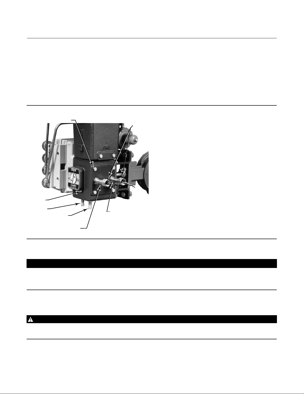
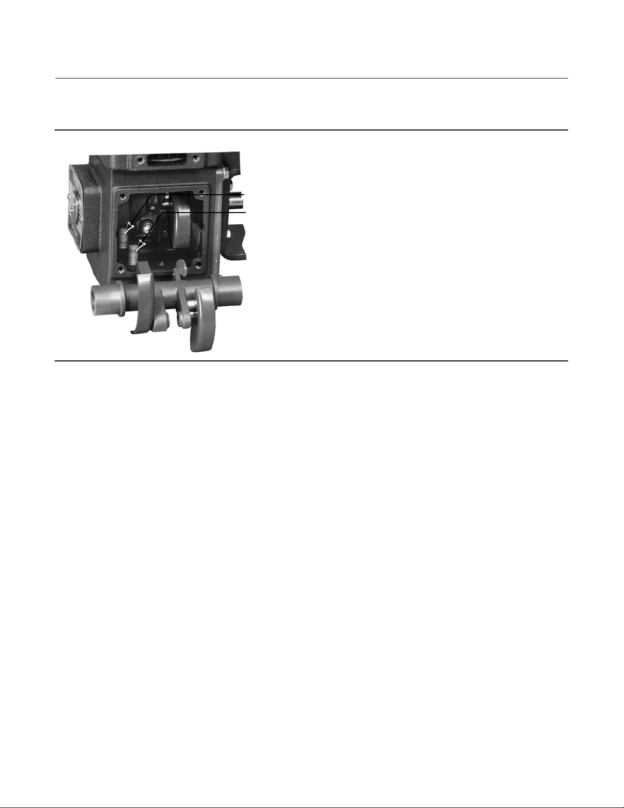
Figure 3.Travel Stops and Switch Positions on the Fisher 1051 and 1052 Size 33 Actuator
HOUSING COVER
ASSEMBLY (KEY 33)
PROXIMITY
SWITCHES
YOKE
MOUNTING
BOSS
UP TRAVEL
STOP
DOWN TRAVEL STOP
MOUNTING POSITION FOR SWITCH
INDICATING BOTTOM OF STROKE
(ACTIVATED BY INNER CAM)
W4738
MOUNTING POSITION FOR
SWITCH INDICATING
TOP OF STROKE
(ACTIVATED BY
OUTER CAM)
7. Tighten the socket head cap screw which compresses the splined lever connection to the valve shaft (see table 2).
CAUTION
When adjusting the travel stop for the closed position of the valve ball or disk, refer to the appropriate valve instruction
manual for detailed procedures. Undertravel or overtravel at the closed position may result in poor valve performance
and/or damage to the equipment.
8. Adjust the up travel stop (see figure 3) so that the valve ball or disk is in the desired position.
WARNING
To avoid personal injury and equipment damage from moving parts, keep fingers and tools clear while stroking the
actuator with the cover removed.
9. Stroke the actuator and adjust the down travel stop so that the valve ball or disk is in the desired position.
6

Instruction Manual
D101322X012
1051 and 1052 Size 33 Actuators
February 2019
10. Make sure that the travel indicator pointer matches the ball or disk position. Remove and install in the proper
position if necessary.
11. Install the cover plate or switch mounting plate (key 59) with cap screws (key 60).
12. Refer to the table of contents for accessory installation procedures.
H Mounting Adaptation
Unless otherwise specified, key numbers referenced in the following procedures are shown in figure 9 for the 1051
actuator and in figure 10 for the 1052 actuator. Unique parts used for the H mounting adaptation are shown in figure
11 for single stub shaft construction and in figure 14 for dual stub shaft construction.
1. To change mounting style or position, the actuator must be separated from the valve body (or other operated
equipment). Remove the cap screws used to attach the actuator to the valve body (or other operated equipment)
and remove the actuator.
2. Determine the desired mounting position. Note that stub shafts are available in standard and reverse constructions
so that proper alignment with the operated equipment can be achieved (see figure 12). Refer to figure 2 for
available mounting styles and positions.
3. If it is necessary to install or change stub shaft(s), the actuator lever (key 27) must be removed. Perform all
applicable operations in the Disassembly portion of the Changing or Replacing Actuator Lever procedure. Install the
stub shafts for the construction desired (refer to figures 11 and 14) and reassemble the actuator.
4. Determine whether the operated equipment will be mounted on the housing cover assembly (key 33) side or on
the actuator housing boss side of the actuator. Depending on the desired mounting style and position, it may be
necessary to move the operated equipment and travel indicator components to opposite sides of the actuator. If
so, remove the travel indicator components, the operated equipment, and the mounting bracket if used. Install the
operated equipment or mounting bracket in the desired position (on the housing cover assembly or on the actuator
housing boss). See table 2 for recommended torque for the mounting cap screws. Install the travel indicator
components on the side of the actuator opposite the operated equipment. Refer to figure 14 for travel indicator
components used with wrench‐operated extensions and manual actuators.
5. Before coupling the operated equipment to the actuator stub shaft, position the equipment as follows:
For push‐down‐to‐activate (open) action, the equipment should be in the fully deactivated (closed) position.
For push‐down‐to‐deactivate (close) action, the equipment should be in the fully activated (open) position.
6. Install the required shaft coupling and the operated equipment.
CAUTION
When adjusting the travel stops to limit rotation, be certain that the rotation produced does not exceed the safe limit of the
operated equipment. Undertravel or overtravel may result in poor performance and/or damage to the equipment.
7. Adjust the up travel stop (see figure 3) so that the operated equipment is in the desired position.
WARNING
To avoid personal injury and equipment damage from moving parts, keep fingers and tools clear while stroking the
actuator with the cover removed.
8. Stroke the actuator and adjust the down travel stop so that the operated equipment is in the desired position.
7

1051 and 1052 Size 33 Actuators
February 2019
Instruction Manual
D101322X012
9. Make sure that the travel indicator pointer matches the ball or disk position. Remove and install in the proper
position if necessary.
10. Refer to the table of contents for accessory installation procedures.
J Mounting Adaptation
Unless otherwise specified, key numbers referenced in the following procedures are shown in figure 9 for the 1051
actuator and in figure 10 for the 1052 actuator. Unique parts used for the J mounting adaptation are shown in figure
13 for single stub shaft construction and in figure 14 for dual stub shaft construction.
1. If the actuator is mounted on a valve body and it is necessary to change mounting style or position, the actuator
must be separated from the valve body. Proceed to the disassembly portion of the Changing or Replacing Actuator
Lever procedure, observe all warnings, perform steps 1 through 6, and return to step 2 which follows.
2. Refer to figure 2 for available mounting styles and positions. The actuator is normally mounted vertically on a valve
body that is installed in a horizontal pipeline.
3. If it is necessary to install or change stub shaft(s), the actuator lever (key 27) must be removed. Perform all
applicable operations in the Disassembly portion of the Changing or Replacing Actuator Lever procedure. Install the
stub shafts for the construction desired as shown in figure 13 and reassemble the actuator.
4. Determine whether the actuator mounting yoke (key 22) will be mounted on the housing cover assembly (key 33)
or on the actuator housing boss. If the desired mounting position and style requires moving the mounting yoke and
travel indicator components to opposite sides of the actuator, remove the travel indicator components, the valve
shaft coupling (key 80 for 1051, or key 90 for 1052), cap screws (key 23), and the mounting yoke. Install the
mounting yoke in the desired position (on the housing cover assembly or on the actuator housing boss). See table 2
for recommended torque for the mounting cap screws. Install the valve shaft coupling on the actuator stub shaft.
Install the travel indicator components on the opposite side of the actuator. See figure 14 for travel indicator
components used with wrench‐operated extensions and manual actuators.
5. Before coupling the valve to the actuator, position the valve ball or disk as follows:
For push‐down‐to‐close action, the valve ball or disk should be in the fully open position.
For push‐down‐to‐open action, the valve ball or disk should be in the fully closed position (see the valve body
instruction manual).
6. The valve shaft coupling (see figure 4) has two keyways lettered A and B (the letters C and D on the coupling are not
used and may be disregarded). Align the appropriate keyway with the keyway in shaft of the operated equipment.
When used with a Fisher butterfly valve body, refer to the table and illustration in figure 4 for proper orientation of
the coupling and valve shaft. Install the woodruff key (key 81 for 1051, key 91 for 1052) in the valve shaft keyseat,
lubricate the inside of the coupling, and slide the valve shaft into the coupling.
7. Install the valve mounting cap screws, washers, and nuts and tighten to the torque value given in the appropriate
valve body instruction manual.
CAUTION
When adjusting the travel stop for the closed position of the valve ball or disk, refer to the appropriate valve body
instruction manual for detailed procedures. Undertravel or overtravel at the closed position may result in poor valve
performance and/or damage to the equipment.
8. Adjust the up travel stop so that the valve ball or disk is in the desired position.
8

Instruction Manual
D101322X012
1051 and 1052 Size 33 Actuators
February 2019
DESIRED
ACTUATOR
ACTION
DESIRED
SHAFT
ROTATION,
DEGREES
ACTUATOR
MOUNTING
POSITION
COUPLING
KEYWAY
(3)
TO USE
VALVE SHAFT KEYWAY TO USE FOR FISHTAIL™
DISK VALVE BODIES
Clockwise to
Close Valve Action
Flow Left
(2)
to Right
(2)
Flow Right
to Left
(1)
(SEE FIGURE 2)
Counterclockwise to
Close Valve Action
(2)
Flow Left
to Right
(2)
(2)
Flow Right
to Left
1 B Nose Tail Tail Nose
Push Down to Open
(PDTO)
60 or 90
2 A Tail Nose Nose Tail
3 B Tail Nose Nose Tail
4 A Nose Tail Tail Nose
1 A Tail Nose Tail Nose
Push Down to Close
(PDTC)
60
(3)
or 90
2 B Tail Nose Tail Nose
3 A Nose Tail Nose Tail
4 B Nose Tail Nose Tail
1. For conventional disk valve bodies, use either valve shaft keyway.
2. When viewed from actuator side of valve body.
3. For 60‐degree rotation with PDTC action, the coupling and actuator output shaft assembly will offset 30 degrees clockwise (for actuator housing construction style B), or counterclock
wise (for actuator housing construction Style A) in the lever when viewed from the splined end of the actuator shaft. 30 degrees is one spline tooth for 9.5, 12.7, and 15.9 mm (3/8, 1/2,
and 5/8 inch) valve shafts and two spline teeth for 19.1 mm (3/4 inch) valve shafts.
Figure 4. Valve Shaft Coupling for the J Mounting Adaptation
1
COUPLING
FULL KEYWAY
LOCATED ON
NOSE AND TAIL
SIDE OF VALVE SHAFT
VALVE SHAFT
(2)
USE APPROPRIATE LETTERED
KEYWAY AS INDICATED IN
PARTIAL KEYWAY
FOR DETERMINING
DISK POSITION
TABLE 5
USE APPROPRIATE
VALVE SHAFT
KEYWAY AS
KEYWAY A
KEYWAY B
ABOVE
KEYWAY A
INDICATED
IN TABLE 5
EXPLODED VIEW OF VALVE SHAFT
AND COUPLING
19A1465‐B
NOTES:
1
A3253*
FOR USE WITH J MOUNTING ADAPTATION.
REFERENCE COUPLING ORIENTATION
FOR TABLE 5
WARNING
To avoid personal injury and equipment damage from moving parts, keep fingers and tools clear while stroking the
actuator with the cover removed.
9. Stroke the actuator and adjust the down travel stop so that the valve ball or disk is in the desired position.
10. Make sure that the travel indicator pointer matches the ball or disk position. Remove and install in the proper
position if necessary.
9
1051 and 1052 Size 33 Actuators
February 2019
11. Refer to the table of contents for accessory installation procedures.
Figure 5. Spring Adjustment
TRAVEL
STOPS
W4767
Instruction Manual
D101322X012
1052 Spring Compression Adjustment
Initial Compression
Key numbers referred to in this procedure are shown in figure 10 unless otherwise specified.
The 1052 nameplate specifies an initial set adjusted into the actuator spring. Initial set is the casing pressure at which
the diaphragm (key 3) and diaphragm rod (key 10) begin to move away from the stop in the upper diaphragm case
(key 1) when the actuator is disengaged from the control valve body or other operated equipment. The initial set was
determined from the service conditions specified when the actuator was ordered, so that when the actuator and valve
are in service, the valve ball or disk seats properly and full travel is obtained with the supply pressure specified on the
order and shown on the nameplate.
Before adjusting spring tension to change initial set, the valve body or other operated equipment must be removed or
otherwise disengaged from the actuator. Refer to the applicable steps given under the appropriate mounting
adaptation in the Actuator Mounting and Changing Actuator Mounting procedure.
To gain access to the spring adjusting screw, either the spring adjuster cover (key 117) or the switch mounting plate
(key 59) must be removed. If externally mounted switches are used, remove them as an assembly by removing the cap
screws (key 75, figure 16) and the switch mounting plate (key 1, figure 16). In order to gain access to the cap screws, it
may be necessary to loosen the hex nuts (key 77, figure 16) and slide the switches away from the actuator housing.
Note that the lower part of the spring adjusting screw (key 74) is notched so that it can be rotated with a screwdriver
or other flat‐bladed tool. To decrease spring compression, rotate the spring adjusting screw to the right (see figure 5).
To increase spring compression, rotate the spring adjusting screw to the left (clockwise when viewed from above).
Adjust the spring so that the diaphragm rod just starts to travel at the initial set pressure specified on the nameplate.
When the desired initial set has been achieved, install the spring adjuster cover or switch mounting plate.
10
 Loading...