

Instruction Manual: FIELDVUE DVC6200 HW1 디지털 밸브 컨트롤러 (DVC6200 HW1 Digital Valve Controller) (Korean) Supported | Fisher
Fisher Instruction Manual: FIELDVUE DVC6200 HW1 디지털 밸브 컨트롤러 (DVC6200 HW1 Digital Valve Controller) (Korean) Supported | Fisher Manuals & Guides

Instruction Manual
D103409X0KR
DVC6200 (HW1) Digital Valve Controller
January 2018
Fisher™ FIELDVUE™ D
VC6200 (HW1) Digital
Valve Controller (Supported) (Korean)
Contents
Introduction 1.................................
Safety Instructions 1............................
Specifications 2................................
Inspection and Maintenance Schedules 2...........
Parts Ordering 2................................
Installation 3..................................
Operation 4...................................
Maintenance 4.................................
Non‐Fisher (OEM) Instruments, Switches, and
Accessories 6..................................
Latest Published Instruction Manual 7..............
Introduction
The product covered in this document is no longer in production. This document, which includes the latest published
version of the instruction manual, is made available to provide updates of newer safety procedures. Be sure to follow
the safety procedures in this supplement as well as the specific instructions in the included instruction manual.
Part numbers in the included instruction manual should not be relied on to order replacement parts. For replacement
parts, contact your Emerson sales office
For more than 20 years, Fisher products have been manufactured with asbestos‐free components. The included
manual might mention asbestos containing parts. Since 1988, any gasket or packing which may have contained some
asbestos, has been replaced by a suitable non‐asbestos material. Replacement parts in other materials are available
from your sales office.
or Local Business Partner.
Safety Instructions
Please read these safety warnings, cautions, and instructions carefully before using the product.
These instructions cannot cover every installation and situation. Do not install, operate, or maintain this product
without being fully trained and qualified in valve, actuator and accessory installation, operation and maintenance. To
avoid personal injury or property damage it is important to carefully read, understand, and follow all of the contents of
this manual, including all safety cautions and warnings. If you have any questions about these instructions, contact
your Emerson sales office or Local Business Partner before proceeding.
www.Fisher.com

DVC6200 (HW1) Digital Valve Controller
January 2018
Instruction Manual
D103409X0KR
Specifications
This product was intended for a specific range of service conditions‐‐pressure, pressure drop, process and ambient
temperature, temperature variations, process fluid, and possibly other specifications. Do not expose the product to
service conditions or variables other than those for which the product was intended. If you are not sure what these
conditions or variables are, contact your Emerson sales office
product serial number and all other pertinent information that you have available.
or Local Business Partner for assistance. Provide the
Inspection and Maintenance Schedules
All products must be inspected periodically and maintained as needed. The schedule for inspection can only be
determined based on the severity of your service conditions. Your installation might also be subject to inspection
schedules set by applicable governmental codes and regulations, industry standards, company standards, or plant
standards.
In order to avoid increasing dust explosion risk, periodically clean dust deposits from all equipment.
When equipment is installed in a hazardous area location (potentially explosive atmosphere), prevent sparks by proper
tool selection and avoiding other types of impact energy. Control Valve surface temperature is dependent upon
process operating conditions.
WARNING
Control valve surface temperature is dependent upon process operating conditions. Personal injury or property damage,
caused by fire or explosion, can result if the valve body surface temperature exceeds the acceptable temperature for the
hazardous area classification. To avoid an increase of instrumentation and/or accessory surface temperature due to process
operating conditions, ensure adequate ventilation, shielding, or insulation of control valve components installed in a
potentially hazardous or explosive atmosphere.
Parts Ordering
Whenever ordering parts for older products, always specify the serial number of the product and provide all other
pertinent information that you can, such as product size, part material, age of the product, and general service
conditions. If you have modified the product since it was originally purchased, include that information with your
request.
WARNING
Use only genuine Fisher replacement parts. Components that are not supplied by Emerson Automation Solutions should
not, under any circumstances, be used in any Fisher product. Use of components not supplied by Emerson may void your
warranty, might adversely affect the performance of the product and could result in personal injury and property damage.
2

Instruction Manual
D103409X0KR
DVC6200 (HW1) Digital Valve Controller
January 2018
Installation
WARNING
Avoid personal injury or property damage from sudden release of process pressure or bursting of parts. Before mounting
the product:
D Do not install any system component where service conditions could exceed the limits given in this manual or the limits
on the appropriate nameplates. Use pressure‐relieving devices as required by government or accepted industry codes
and good engineering practices.
D Always wear protective gloves, clothing, and eyewear when performing any installation operations.
D Do not remove the actuator from the valve while the valve is still pressurized.
D Disconnect any operating lines providing air pressure, electric power, or a control signal to the actuator. Be sure the
actuator cannot suddenly open or close the valve.
D Use bypass valves or completely shut off the process to isolate the valve from process pressure. Relieve process pressure
from both sides of the valve.
D Vent the pneumatic actuator loading pressure and relieve any actuator spring precompression so the actuator is not
applying force to the valve stem; this will allow for the safe removal of the stem connector.
D Use lock‐out procedures to be sure that the above measures stay in effect while you work on the equipment.
D The valve packing box might contain process fluids that are pressurized, even when the valve has been removed from the
pipeline. Process fluids might spray out under pressure when removing the packing hardware or packing rings, or when
loosening the packing box pipe plug. Cautiously remove parts so that fluid escapes slowly and safely.
D The instrument is capable of supplying full supply pressure to connected equipment. To avoid personal injury and
equipment damage, caused by sudden release of process pressure or bursting of parts, make sure the supply pressure
never exceeds the maximum safe working pressure of any connected equipment.
D Severe personal injury or property damage may occur from an uncontrolled process if the instrument air supply is not
clean, dry and oil‐free, or noncorrosive gas. While use and regular maintenance of a filter that removes particles larger
than 40 microns will suffice in most applications, check with an Emerson Automation Solutions field office and Industry
Instrument air quality standards for use with corrosive gas or if you are unsure about the proper amount or method of
air filtration or filter maintenance.
D For corrosive media, make sure the tubing and instrument components that contact the corrosive media are of suitable
corrosiion-resistant material. The use of unsuitable materials might result in personal injury or property damage due to
the uncontrolled release of the corrosive media.
D If natural gas or other flammable or hazardous gas is to be used as the supply pressure medium and preventive
measures are not taken, personal injury and property damage could result from fire or explosion of accumulated gas or
from contact with hazardous gas. Preventive measures may include, but are not limited to: Remote venting of the unit,
re‐evaluating the hazardous area classification, ensuring adequate ventilation, and the removal of any ignition sources.
D To avoid personal injury or property damage resulting from the sudden release of process pressure, use a high‐pressure
regulator system when operating the controller or transmitter from a high‐pressure source.
The instrument or instrument/actuator assembly does not form a gas‐tight seal, and when the assembly is in an
enclosed area, a remote vent line, adequate ventilation, and necessary safety measures should be used. Vent line piping
should comply with local and regional codes and should be as short as possible with adequate inside diameter and few
bends to reduce case pressure buildup. However, a remote vent pipe alone cannot be relied upon to remove all
hazardous gas, and leaks may still occur.
D Personal injury or property damage can result from the discharge of static electricity when flammable or hazardous
gases are present. Connect a 14 AWG (2.08 mm
flammable or hazardous gases are present. Refer to national and local codes and standards for grounding
requirements.
D Personal injury or property damage caused by fire or explosion may occur if electrical connections are attempted in an
area that contains a potentially explosive atmosphere or has been classified as hazardous. Confirm that area
classification and atmosphere conditions permit the safe removal of covers before proceeding.
2
) ground strap between the instrument and earth ground when
3

DVC6200 (HW1) Digital Valve Controller
January 2018
D For instruments with a hollow liquid level displacer, the displacer might retain process fluid or pressure. Personal injury
or property damage due to sudden release of pressure, contact with hazardous fluid, fire, or explosion can be caused by
puncturing, heating, or repairing a displacer that is retaining process pressure or fluid. This danger may not be readily
apparent when disassembling the sensor or removing the displacer. Before disassembling the sensor or removing the
displacer, observe the appropriate warnings provided in the sensor instruction manual.
D Personal injury or property damage, caused by fire or explosion from the leakage of flammable or hazardous gas, can
result if a suitable conduit seal is not installed. For explosion‐proof applications, install the seal no more than 457 mm
(18 inches) from the instrument when required by the nameplate. For ATEX applications use the proper cable gland
certified to the required category. Equipement must be installed per local and national electric codes.
D Check with your process or safety engineer for any additional measures that must be taken to protect against process
media.
D If installing into an existing application, also refer to the WARNING in the Maintenance section.
Instruction Manual
D103409X0KR
Special Instructions for Safe Use and Installations in Hazardous Locations
Certain nameplates may carry more than one approval, and each approval may have unique installation requirements
and/or conditions of safe use. Special instructions are listed by agency/approval. To get these instructions, contact
Emerson sales office
or Local Business Partner. Read and understand these special conditions of use before installing.
WARNING
Failure to follow conditions of safe use could result in personal injury or property damage from fire or explosion, or area
re‐classification.
Operation
With instruments, switches, and other accessories that are controlling valves or other final control elements, it is
possible to lose control of the final control element when you adjust or calibrate the instrument. If it is necessary to
take the instrument out of service for calibration or other adjustments, observe the following warning before
proceeding.
WARNING
Avoid personal injury or equipment damage from uncontrolled process. Provide some temporary means of control for the
process before taking the instrument out of service.
Maintenance
WARNING
Before performing any maintenance operations on an actuator‐mounted instrument or accessory:
4

Instruction Manual
D103409X0KR
D To avoid personal injury, always wear protective gloves, clothing, and eyewear.
D Provide some temporary measure of control to the process before taking the instrument out of service.
D Provide a means of containing the process fluid before removing any measurement devices from the process.
D Disconnect any operating lines providing air pressure, electric power, or a control signal to the actuator. Be sure the
actuator cannot suddenly open or close the valve.
D Use bypass valves or completely shut off the process to isolate the valve from process pressure. Relieve process pressure
from both sides of the valve.
D Vent the pneumatic actuator loading pressure and relieve any actuator spring precompression so the actuator is not
applying force to the valve stem; this will allow for the safe removal of the stem connector.
D Personal injury or property damage may result from fire or explosion if natural gas or other flammable or hazardous gas
is used as the supply medium and preventive measures are not taken. Preventive measures may include, but are not
limited to: Remote venting of the unit, re‐evaluating the hazardous area classification, ensuring adequate ventilation,
and the removal of any ignition sources. For information on remote venting of this instrument, refer to the Installation
section.
D Use lock‐out procedures to be sure that the above measures stay in effect while you work on the equipment.
D The valve packing box might contain process fluids that are pressurized, even when the valve has been removed from the
pipeline. Process fluids might spray out under pressure when removing the packing hardware or packing rings, or when
loosening the packing box pipe plug. Cautiously remove parts so that fluid escapes slowly and safely.
D Check with your process or safety engineer for any additional measures that must be taken to protect against process
media.
D On an explosion‐proof instrument, remove the electrical power before removing the instrument covers in a hazardous
area. Personal injury or property damage may result from fire and explosion if power is applied to the instrument with
the covers removed.
DVC6200 (HW1) Digital Valve Controller
January 2018
Instruments Mounted on Tank or Cage
WARNING
For instruments mounted on a tank or displacer cage, release trapped pressure from the tank and lower the liquid level to a
point below the connection. This precaution is necessary to avoid personal injury from contact with the process fluid.
Instruments With a Hollow Displacer or Float
WARNING
For instruments with a hollow liquid level displacer, the displacer might retain process fluid or pressure. Personal injury
and property might result from sudden release of this pressure or fluid. Contact with hazardous fluid, fire, or explosion can
be caused by puncturing, heating, or repairing a displacer that is retaining process pressure or fluid. This danger may not
be readily apparent when disassembling the sensor or removing the displacer. A displacer that has been penetrated by
process pressure or fluid might contain:
D pressure as a result of being in a pressurized vessel
D liquid that becomes pressurized due to a change in temperature
D liquid that is flammable, hazardous or corrosive.
Handle the displacer with care. Consider the characteristics of the specific process liquid in use. Before removing the
displacer, observe the appropriate warnings provided in the sensor instruction manual.
5

DVC6200 (HW1) Digital Valve Controller
January 2018
Instruction Manual
D103409X0KR
Non‐Fisher (OEM) Instruments, Switches, and Accessories
Installation, Operation, and Maintenance
Refer to the original manufacturer's documentation for Installation, Operation and Maintenance safety information.
Neither Emerson, Emerson Automation Solutions, nor any of their affiliated entities assumes responsibility for the selection, use or maintenance
of any product. Responsibility for proper selection, use, and maintenance of any product remains solely with the purchaser and end user.
Fisher and FIELDVUE are marks owned by one of the companies in the Emerson Automation Solutions business unit of Emerson Electric Co. Emerson
Automation Solutions, Emerson, and the Emerson logo are trademarks and service marks of Emerson Electric Co. All other marks are the property of their
respective owners.
The contents of this publication are presented for informational purposes only, and while every effort has been made to ensure their accuracy, they are not
to be construed as warranties or guarantees, express or implied, regarding the products or services described herein or their use or applicability. All sales are
governed by our terms and conditions, which are available upon request. We reserve the right to modify or improve the designs or specifications of such
products at any time without notice.
Emerson Automation Solutions
Marshalltown, Iowa 50158 USA
Sorocaba, 18087 Brazil
Cernay, 68700 France
Dubai, United Arab Emirates
Singapore 128461 Singapore
www.Fisher.com
6
E 2018 Fisher Controls International LLC. All rights reserved.

사용 설명서
D103409X0KR
DVC6200 디지털 밸브 컨트롤러
2013년 12월
Fisherr FIELDVUE
™
컨트롤러
설명서적용대상
기기 레벨 HC, AD, PD, ODV AC
장치 유형 03 07
장치 수정 2 2
하드웨어 수정 1 1
펌웨어 수정 9, 10 및 11 9, 10 및 11
DD 수정 8 1
목차
단원 1 소개 3..........................
설명서 범위 3.....................................
이 설명서에 사용된 규칙 3..........................
설명 4............................................
규격 5............................................
관련 문서 8.......................................
교육 서비스 9.....................................
단원 2 설치 11.........................
DVC6200 장착 11..................................
DVC6205 베이스 유닛 장착 14.......................
DVC6215 피드백 유닛 장착 16.......................
최대 210mm(8.25인치) 슬라이딩 스템 선형
액추에이터 18..............................
210mm(8.25인치) 트래블 이상 Fisher 로타리
액추에이터 및 슬라이딩 스템 선형
액추에이터 20..............................
GX 액추에이터 22.............................
쿼터-턴 로타리 액추에이터 25...................
Fisher 67CFR 필터 레귤레이터(regulator) 장착 26......
공압식 연결부 26....................................
압력 26...........................................
공급 27...........................................
출력 연결구 28................................
솔레노이드 밸브 테스트를 지원하기 위한 특별
구성 29....................................
벤트홀 30.....................................
배선및전기연결 30................................
4-20mA 루프 연결 31...............................
원격 트래블 센서 연결 32...........................
컨트롤 작업 34......................................
컨트롤 시스템 요구 사항 34.........................
HART 필터 34.................................
가용 전압 35..................................
적합 전압 37..................................
DVC6200 디지털 밸브
W9713
최대 케이블 Capacitance 37.........................
Rosemountt333 HART Tri-Loopt HART-to-Analog
Signal Converter와 함께 설치 38......................
단원 3 기본 설정 41....................
기기 모드 41......................................
구성 보호 41......................................
기본 설정 42......................................
설정 마법사 42................................
성능 튜너 44..................................
밸브 응답 안정화/최적화 45.....................
단원 4 세부 설정 47....................
모드 및 보호 49....................................
모드 49.......................................
보호 50.......................................
보호및응답제어 52...........................
튜닝 52.......................................
트래블 튜닝 52................................
필수 설정(Integral Settings) 55..................
압력 튜닝 55..................................
트래블/압력 제어(Travel/Pressure Control) 56.....
입력 특성화 58................................
사용자 지정 특성화 정의 58.....................
동적 응답(Dynamic Response) 59................
www.Fisher.com
DVC6200 디지털 밸브 컨트롤러
2013년 12월
사용 설명서
D103409X0KR
목차(계속)
Alerts 설정 60....................................
전자 alerts 61.................................
프로세서 손상 alerts 61.........................
센서 alerts 62.................................
환경 alerts 62.................................
트래블 alerts 63...............................
트래블 내역 alerts 65...........................
SIS alerts(기기 레벨 ODV) 66...................
Alerts 기록 67.................................
상태 68...........................................
기기 69...........................................
밸브 및 액추에이터 71..............................
SIS/부분 스트로크(기기 레벨 ODV) 73................
단원 5 보정 77.........................
보정 개요 77......................................
보정 77...........................................
트래블 보정 78................................
자동 보정 78..................................
수동 보정 79..................................
센서 보정 80......................................
압력 센서 보정 80..............................
아날로그 입력 보정 82..........................
릴레이 조정 83....................................
더블-액팅 릴레이 83.............................
싱글-액팅 릴레이 85.............................
공장 기본 설정 복원 85.............................
단원6장치변수및진단보기 87.........
장치 진단 87......................................
장치 변수 93......................................
단원7유지관리및문제해결 97.........
마그네틱바 교체 98................................
모듈 베이스 유지 관리 98...........................
필요한 공구 98................................
구성품 교체 99................................
모듈 베이스 제거 99............................
모듈 베이스 교체 100...........................
서브 모듈 유지 관리 모듈 유지 관리 101...........
I/P 컨버터 101................................
Printed wiring board(PWB) 어셈블리 103..........
공압 릴레이 105...............................
게이지, 파이프 플러그 또는 타이어 밸브 105.......
단자함 106........................................
단자함 제거 106...............................
단자함 교체 107...............................
DVC6215 피드백 유닛 116..........................
문제 해결 107.....................................
가용 전압 확인 107.................................
루프 회선을 방해하지 않고 루프 전류 검사 108.........
단원 8 부품 113........................
부품 주문 113.....................................
부품 키트 113.....................................
부품 목록 114.....................................
하우징 114....................................
공통 부품 114.................................
모듈 베이스 114...............................
I/P 컨버터 어셈블리 115........................
릴레이 115....................................
단자함 115....................................
피드백 연결 단자함 115.........................
PWB 어셈블리 116.............................
압력 게이지, 파이프 플러그 또는 타이어
밸브 어셈블리 116...........................
DVC6215 피드백 유닛 116......................
HART 필터 116................................
부록 A 작동 원리 123...................
HART 통신 123....................................
DVC6200 디지털 밸브 컨트롤러 123..................
부록 B 필드 커뮤니케이터 메뉴 트리 127..
용어 135..............................
찾아보기 143..........................
FIELDVUE DVC6200 디지털 밸브 컨트롤러는 PlantWeb™ 디지털 플랜트 설계의 핵심 구성 요소입니다.
디지털 밸브 컨트롤러는 밸브 진단 데이터를 캡처 및 전달하여 PlantWeb을 구동합니다. ValveLink™
소프트웨어와 함께 DVC6200은 사용자에게 실제 스템 포지션, 기기 입력 신호 및 액추에이터 공기 압력 등의
밸브 성능에 대한 정확한 정보를 제공합니다. 이 정보를 사용하여 디지털 밸브 컨트롤러 자체뿐 아니라
장착된 밸브 및 액추에이터를 진단합니다.
2

사용 설명서
D103409X0KR
소개
2013년 12월
단원 1 소개
설명서 범위
이 사용 설명서는 모든 기기와 함께 제공되는 DVC6200 Series Quick Start Guide(D103556X012)의 보충 자료입니다. 이 사용
설명서에는 FIELDVUE DVC6200 디지털 밸브 컨트롤러, 장치 수정 버전 2, 펌웨어 수정 버전 9, 10과 11, 기기 레벨 AC, HC,
AD, PD 및 ODV에 대한 제품 사양, 설치 정보, 참고 자료, 사용자 지정 설정 정보, 유지 보수 절차, 교체 부품 정보 등이 포함되어
있습니다.
참고
DVC6200 디지털 밸브 컨트롤러에는 펌웨어 9, 10 또는 11이 필요합니다. printed wiring board(PWB)의 펌웨어가이전버전인
경우 DVC6200을 사용하기 전에 업데이트해야 합니다.
참고
DVC6200 디지털 밸브 컨트롤러에 대한 모든 참고는 별도로 언급되지 않는 한 DVC6205 베이스 유닛에도 해당됩니다.
이 사용 설명서에서는 475 필드 커뮤니케이터(장치 설명 수정 버전 1과 2)를 사용하여 기기를 설정 및 보정하는 방법에 대해
설명합니다. 사용자는 Fisher ValveLink 소프트웨어 버전 10.2 또는 그 이상의 버전을 사용하여 밸브 및 기기를 설치, 보정 및
진단할 수도 있습니다. 기기에서 사용되는 ValveLink 소프트웨어에 대한 자세한 내용은 ValveLink 소프트웨어 도움말 또는
설명서를 참조하십시오.
밸브, 액추에이터, 부속품의 설치, 작동, 유지 관리에 충분한 훈련을 받지 않고 자격이 없을 경우 DVC6200 디지털 밸브
컨트롤러를 설치, 작동 및 유지 관리하지 마십시오. 상해나 자산 손해를 피하려면 모든 안전 주의사항 및 경고를 포함하여 이
설명서의 모든 내용을 주의 깊게 읽고, 이해하고, 따르는 것이 중요합니다. 이 설명서와 관련하여 의문 사항이 있을 경우에는
진행하기 전에 Emerson Process Management 영업소에 문의하십시오.
이 설명서에 사용된 규칙
필드 커뮤니케이터를 사용하여 액세스할 수 있는 절차 및 매개 변수에 대한 탐색 경로와 빠른 키 시퀀스가 포함되어 있습니다.
예를 들어 설치 마법사에 액세스하는 방법은 다음과 같습니다.
필드 커뮤니케이터 Configure / Guided Setup > Setup Wizard (1-1-1)
필드 커뮤니케이터 메뉴 트리는 부록 B를 참조하십시오.
참고
이 설명서에 사용된 필드 커뮤니케이터 메뉴 시퀀스는 기기 레벨 HC, AD, PD 및 ODV에 적용됩니다. AC 메뉴 시퀀스는 부록
B에서 AC 메뉴 트리를 참조하십시오.
3
소개
2013년 12월
사용 설명서
D103409X0KR
설명
DVC6200 디지털 밸브 컨트롤러(그림 1‐1 및 1‐2)는 마이크로프로세서 기반의 전류-공압 기기와 통신합니다. 입력 전류 신호를
출력 공기압으로 변환하는 일반적인 기능 외에도 DVC6200 디지털 밸브 컨트롤러는 HARTr 통신 프로토콜을 사용하여
프로세스 작업에 중요한 정보에 쉽게 액세스할 수 있게 해줍니다. 밸브 또는 현장 정션 박스에서 필드 커뮤니케이터를
사용하거나 제어실 내의 운전자 콘솔 또는 개인용 컴퓨터를 사용하여 프로세스의 주 구성 요소인 컨트롤 밸브 자체에서
제공하는 정보를 확인할 수 있습니다.
개인용 컴퓨터와 ValveLink 소프트웨어 또는 AMS 제품군(지능형 장치 관리자 또는 필드 커뮤니케이터)을 사용하면 DVC6200
디지털 밸브 컨트롤러로 여러 작업을 수행할 수 있습니다. 소프트웨어 수정 레벨, 메시지, 태그, 설명자 및 날짜가 포함된 일반
정보를 얻을 수 있습니다.
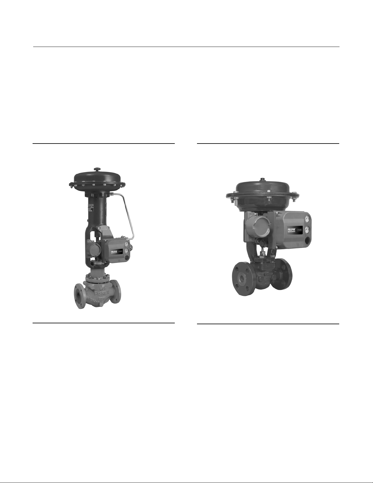
그림 1‐1. Fisher 슬라이딩-스템 밸브 액추에이터에
장착된 FIELDVUE DVC6200 디지털 밸브 컨트롤러
W9643
그림 1‐2. Fisher GX 컨트롤 밸브에 일체형으로
장착된 FIELDVUE DVC6200 디지털 밸브 컨트롤러
W9616
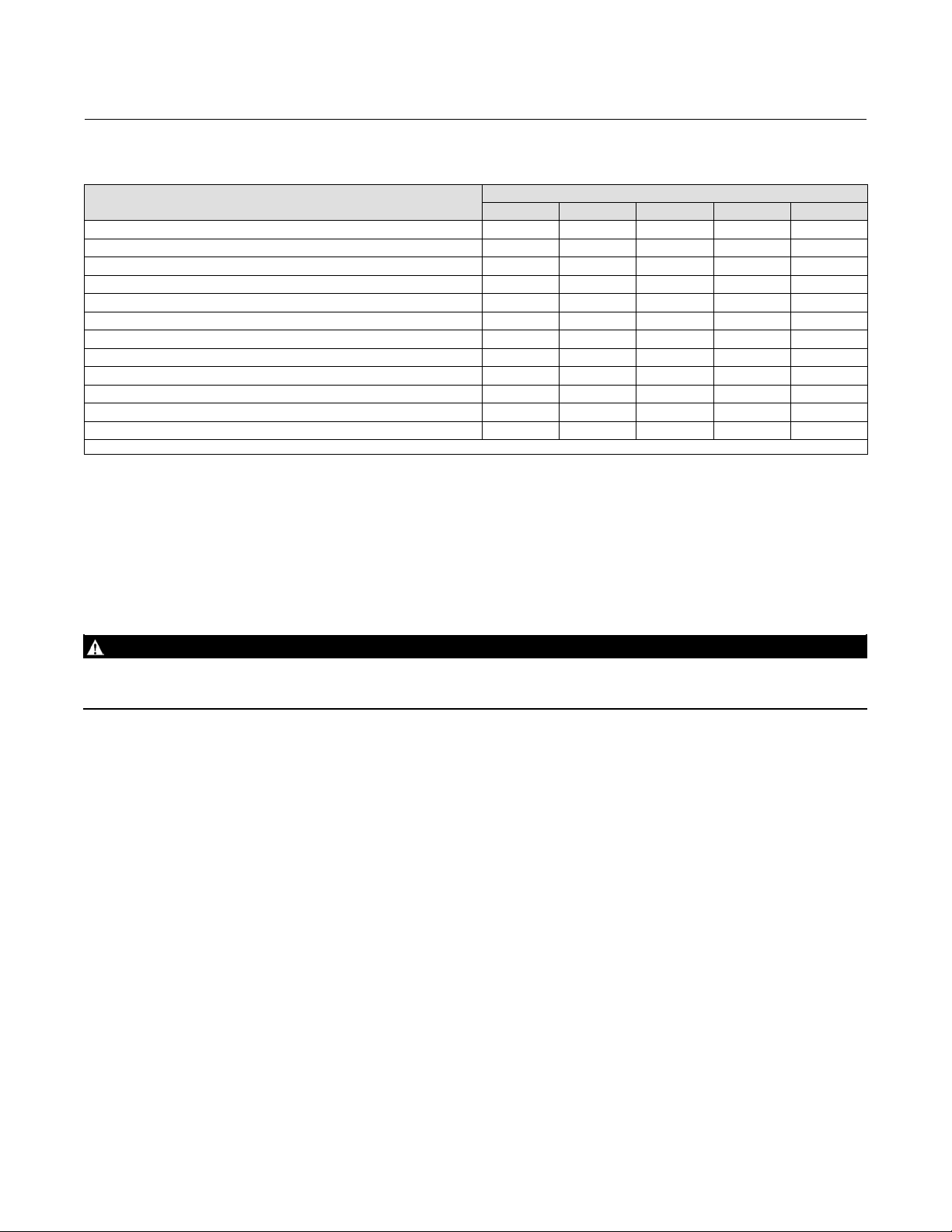
문제 해결 시 진단 정보를 활용할 수 있습니다. 입력 및 출력 구성 매개 변수를 설정하고 디지털 밸브 컨트롤러를 보정할 수
있습니다. 각 진단 계층의 기능에 대한 자세한 내용은 표 1‐1을 참조하십시오.
4
사용 설명서
D103409X0KR
표1‐1.기기레벨기능
기능
자동 보정 X X X X X
사용자 지정 특성화 X X X X X
버스트 통신 X X X X
Alerts X X X X
스텝 응답, 구동 신호 테스트 및 동적 오차폭 X X X
고급 진단(밸브 시그너처) X X X
성능 튜너 X X X
트래블 제어 - 압력 폴백 X X X
공급 압력 센서 X X X
성능 진단 X X
솔레노이드 밸브 테스트 X
선도/지연 기준점 필터
1. 컴프레서 서지 방지 애플리케이션용 Fisher 최적화 디지털 밸브에 대한 자세한 내용은 브로셔 부품 번호 D351146X012/D351146X412를 참조하십시오.
(1)
AC HC AD PD ODV
HART 프로토콜을 사용하여 현장 정보를 컨트롤 시스템에 통합하거나 단일 루프 단위로 수신할 수 있습니다.
진단 레벨
2013년 12월
소개
X
DVC6200 디지털 밸브 컨트롤러는 밸브에 장착된 표준 공기식 및 전기-공기식 포지셔너를 대체하기 위해 디자인되었습니다.
규격
경고
자세한 규격은 표 1‐2를 참조하십시오. 포지셔닝 기기를 잘못 구성하면 제품 고장, 자산 손실이 발생하거나 상해를 입을 수
있습니다.
DVC6200 디지털 밸브 컨트롤러의 규격은 표 1‐2에 나와 있습니다. 필드 커뮤니케이터의 규격은 필드 커뮤니케이터의 제품
설명서에서 확인할 수 있습니다.
5

소개
격
2013년 12월
표1‐2.규
사용 설명서
D103409X0KR
가능한 장착
DVC6200 디지털 밸브 컨트롤러 또는 DVC6215 피드백
유닛: J Fisher GX 컨트롤 밸브에 일체형으로 장착 가능
J Fisher 로타리 액추에이터에 윈도우식 장착 가능
J 리니어(linear) 슬라이딩 스템 적용 J 쿼터-턴 로타리
적용
2인치 파이프스탠드 또는 wall mounting(원격 장착)용
DVC6205 베이스 유닛
DVC6200 디지털 밸브 컨트롤러 또는 DVC6215 피드백
유닛은 IEC 60534-6-1, IEC 60534-6-2, VDI/VDE 3845 및
NAMUR 장착 표준을 준수하는 다른 액추에이터에 장착할
수도 있습니다.
입력 신호
Point-to-Point:.
아날로그 입력 신호 :
4-20mA DC nominal : 분할 범위
가능 기기 단자에서 가용 최소 전압은 아날로그 제어의
경우 : 10.5 VDC HART 통신의 경우 : 11VDC
최소 제어 전류:
최소 전류(w/o Micro Processer Restart):
최대 전압:
Overcurrent protected
4.0mA
3.5mA
30VDC
,
Reverse Polarity protected
Multi-drop:
기기 전력:
11~30VDC @ 8mA
Reverse Polarity protected
공급 압력
(1)
권장 최소값: 최대 액추에이터 요구치보다 0.3bar(5psig)
높음
최대값: 10.0bar(145psig)와 액추에이터의 최대 압력
정격중낮은값
유체: 공기 또는 천연 가스
공기:
공급 압력은 ISA 표준 7.0.01 요건을 충족하는
깨끗하고 건조한 공기여야 합니다.
천연 가스:
oil-free, noncorrosive의 상태여야 합니다. H
천연가스는 반드시 깨끗하고 건조하며,
S 용량은
2
20ppm을 초과해서는 안 됩니다.
최대 허용치 40마이크로 미터 입자를 가진 에어
시스템에서 사용 가능합니다. 5마이크로 미터 수준의
입자 크기로 추가 여과하는 것을 권장합니다. 윤활제
함유가 1ppm(weight (w/w) 또는 volume (v/v)basis)을
초과해서는 안 됩니다. 공급 에어의 응축은 최소화되어야
합니다.
출력 신호
공압 신호, 완전 공급 압력까지
최소 스판: 0.4bar(6psig)
최대 스판: 9.5bar(140psig)
동작: J 더블 액팅, J 싱글 다이렉트 액팅, J 리버스 액팅
정상 상태 공기 소비
(2)(3)
표준 릴레이:
1.4bar(20psig)에서의 공급 압력:
0.38normal m3/hr(14scfh) 미만(기준 대기압)
5.5bar(80psig)에서의 공급 압력:
1.3normal m3/hr(49scfh) 미만(기준 대기압)
Low Bleed 릴레이
1.4bar(20psig)에서의공급압력:
평균값 0.056 normal m
5.5bar(80psig)에서의공급압력:
평균값 0.184 normal m
최대 출력 용량
(2)(3)
3
/hr(2.1 scfh)
3
/hr(6.9 scfh)
1.4bar(20psig)에서의 공급압력 : 10.0 normal m3/hr
(375scfh)
5.5bar(80psig)에서의 공급압력 : 29.5 normal m
(1100scfh)
작동 대기 온도
(1)(4)
-40~85_C(-40~185_F)
-52~85_C(-62~185_F) - 극한 온도 옵션을 사용하는
기기(fluorosilicone elastomers)
-52~125_C(-62~257_F) - 원격 장착 피드백 유닛
독립적 선형성
(5)
일반적인 값: 출력 스판의 +0.50%
전자기 적합성
EN 61326-1(초판)
내성-EN61326-1표준의표2에따른산업지역.
성능은 아래 표 1‐3에 나타나 있습니다.
방출 - 클래스 A
ISM 장비 등급: 그룹 1 클래스 A
낙뢰및서지방지-표 1‐3에 서지 내성으로 지정된 낙뢰
내성 수준입니다. 상용 과전류 방지 장치를 사용하면
서지를 더욱 철저히 방지할 수 있습니다.
-계속-
3
/hr
6
사용 설명서
D103409X0KR
표1‐2.규격(계속)
소개
2013년 12월
진동 테스트 방법
ANSI/ISA-S75.13.01 Section 5.3.5에 따라
테스트되었으며, 세 축 모두에 대해 공진 주파수 조사를
수행했습니다. 이 기기는 각 주요 공진에서 ISA에서
지정한 30분 내구 시험을 거쳤습니다.
입력 임피던스(impedance)
DVC6200 능동 전자 회로의 입력 임피던스(impedance)는
순수 저항이 아닙니다. 저항 부하 사양과 비교하여 동등한
550ohm 임피던스(impedance)를 사용할 수 있습니다. 이
값은 11V @ 20mA에 해당합니다.
습도 테스트 방법
IEC 61514-2에 따라 테스트되었습니다.
전기 분류
Hazardous Area Approvals:
CSA - Intrinsically Safe, Explosion‐proof,
Division 2, Dust Ignition‐proof
FM - Intrinsically Safe, Explosion‐proof, Non‐incendive,
Dust Ignition‐proof
ATEX - Intrinsically Safe, Flameproof, Type n
IECEx - Intrinsically Safe, Flameproof, Type n
Electrical Housing:
CSA - Type 4X, IP66
FM - NEMA 4X
ATEX -IP66
IECEx -IP66
기타 분류/인증
천연가스 인증, 싱글 씰 계기 - CSA, FM, ATEX 및 IECEx
FSETAN - Federal Service of Technological, Ecological
and Nuclear Inspectorate(생태환경기술원자력감독청)(러
시아)
GOST-R - 러시아 GOST-R
INMETRO - National Institute of Metrology, Quality and
Technology(국립도량형·표준화·산업품질인증원)(브라질)
KGS - 한국가스안전공사(대한민국)
NEPSI - National Supervision and Inspection Centre for
Explosion Protection and Safety of Instrumentation(폭발
방지및안전장치감독및조사센터)(중국)
PESO CCOE - Petroleum and Explosives Safety
Organisation - Chief Controller of Explosives(석유자원 및
폭발물 안전기구 - 폭발물 관리 사무국)(인도)
TIIS - Technology Institution of Industrial Safety(산업
안전 기술 협회)(일본)
분류/인증 관련 구체적 정보는 Emerson Process
Management 영업소에 문의하십시오.
연결부
공급 압력: 67CFR 레귤레이터(regulator) 장착용 1/4NPT
내부 및 필수 패드
출력 압력: 1/4NPT 내부
배관: 3/8인치 권장
압력 배출: 3/8NPT 내부
전기: 1/2NPT 내부, M20 어댑터(옵션)
액추에이터 호환성
스템 트래블(선형 슬라이딩 스템):
최소:
6.5mm(0.25인치)
최대:
606mm(23.875인치)
샤프트 회전(쿼터-턴 로타리):
최소:
45도
최대:
90도
무게
DVC6200: 3.5kg(7.7lbs)
DVC6205: 4.1kg(9lbs)
DVC6215: 1.4kg(3.1lbs)
구성 자재
하우징, 모듈 베이스 및 단자함: A03600 low copper
aluminum alloy(표준)
덮개: 열가소성 폴리에스터
Elastomers: Nitrile(표준)
Fluorosilicone(극한 온도)
옵션
J 공급및출력압력게이지또는
J 타이어 밸브 J 일체형 필터 레귤레이터(regulator)
J Low Bleed 릴레이 J 극한 온도 J 천연가스 인증, 싱글
씰계기
자세한 내용은 Emerson Process Management 영업소에
문의하거나 www.FIELDVUE.com을 참조하십시오.
-계속-
J 원격 장착
(6)
7

소개
2013년 12월
표1‐2.규격(계속)
사용 설명서
D103409X0KR
SEP 선언
Fisher Controls International LLC는 이 제품이
PED(Pressure Equipment Directive) 97/23/EC의 Article 3
paragraph 3에 적합함을 선언합니다. 이 제품은
SEP(Sound Engineering Practice)에 따라 설계 및
참고: 전문 기기 용어는 ANSI/ISA Standard 51.1 - Process Instrument Terminology. 에 정의되어 있습니다.
1. 이 문서와 그 밖의 모든 적용 가능한 코드 또는 표준에 명시된 압력/온도 제한을 초과해서는 안 됩니다.
2. Normal m
3. 다이렉트 싱글-액팅 기준 1.4bar(20psig)에서의 값, 더블-액팅 릴레이 기준 5.5bar(80psig)에서의 값.
4. 온도 제한은 위험 지역 인증에 따라 다릅니다.
5. 19mm(0.75인치) 미만의 트래블 또는 60도 미만의 샤프트 회전에는 적용되지 않습니다. 또한 스토로크가 긴 애플리케이션의 디지털 밸브 컨트롤러에도 적용되지 않습니다.
6. 베이스 유닛과 피드백 유닛을 연결하려면 최소 전선 크기가 18 ~ 22AWG인 4도체 쉴드 케이블과 금속 전선관 또는 가요 전선관이 필요합니다. 베이스 유닛 출력 연결과 액추에이터 사이의
3
/hour(기준 대기압) - 0_C 및 1.01325bar 절대 습도에서의 시간당 기준 대기압 입방미터 Scfh - 60_F 및 14.7psia에서의 시간당 표준 입방피트.
공압 튜빙 길이는 91m(300피트)에서 테스트되었습니다. 15m(50피트)에 설치했을 때에는 성능이 저하되지 않았습니다. 91m에 설치했을 때에는 공압 지연이 최소가 되었습니다.
제조되었으며, PED 적합성과 관련된 CE 마크를 부착할
수 없습니다.
기타
그러나
Directive에 적합함을 나타내는 CE 마크는 부착할
적용 가능한 European Community
수도
있습니다.
표 1‐3. EMC 요약 결과 - 내성
포트 현상 기본 표준 테스트 레벨
정전기 방전(ESD) IEC 61000-4-2
외장
I/O 신호/제어
성능 기준: +/- 1% 유효
1. A = 테스트 중에는 저하되지 않음. B = 테스트 중에 일시적으로 저하되지만 자동 복구됨
2. 보조 스위치 기능 제외 - 성능 기준 B 충족
방사되는 전자기장 IEC 61000-4-3
정격 전력 주파수 자기장 IEC 61000-4-8 50/60Hz에서 30A/m A A
버스트 IEC 61000-4-4 1kV A
서지 IEC 61000-4-5 1kV B B
전도성 RF IEC 61000-4-6 3Vrms에서 150kHz~80MHz A A
4kV 접촉
8kV 공중
80~1000MHz @ 10V/m(1kHz AM @ 80% 포함)
1400~2000MHz @ 3V/m(1kHz AM @ 80% 포함)
2000~2700MHz @ 1V/m (1kHz AM @ 80% 포함)
성능 기준
지점 간 멀티 드롭
(2)
A
A A
(2)
(1)
A
A
관련 문서
이 단원에는 DVC6200 디지털 밸브 컨트롤러와 관련된 정보가 포함된 다른 문서가 명시되어 있습니다. 이러한 문서는 다음과
같습니다.
D Bulletin 62.1:DVC6200 - Fisher FIELDVUE DVC6200 Digital Valve Controller (D103415X012)
D Bulletin 62.1:DVC6200 HC - Fisher FIELDVUE DVC6200 Digital Valve Controller (D103423X012)
D Bulletin 62.1:DVC6200(S1) Fisher FIELDVUE DVC6200 Digital Valve Controller Dimensions (D103543X012)
D Fisher FIELDVUE DVC6200 Series Digital Valve Controller Quick Start Guide (D103556X012)
D FIELDVUE Digital Valve Controller Split Ranging - Supplement to HART Communicating Fisher FIELDVUE Digital Valve
Controller Instruction Manuals (D103262X012)
D Using FIELDVUE Instruments with the Smart HART Loop Interface and Monitor (HIM) - Supplement to HART
Communicating Fisher FIELDVUE Instrument Instruction Manuals (D103263X012)
D Using FIELDVUE Instruments with the Smart Wireless THUMt Adapter and a HART Interface Module (HIM) - Supplement
to HART Communicating Fisher FIELDVUE Instrument Instruction Manuals
D Audio Monitor for HART Communications - Supplement to HART Communicating Fisher FIELDVUE Instrument Instruction
Manuals (D103265X012)
8

사용 설명서
D103409X0KR
D HART Field Device Specification - Supplement to Fisher FIELDVUE DVC6000 and DVC6200 HW1 Digital Valve Controller
Instruction Manuals (D103649X012)
D Using the HART Tri-Loop HART-to-Analog Signal Converter with FIELDVUE Digital Valve Controllers - Supplement to HART
Communicating FIELDVUE Instrument Instruction Manuals (D103267X012)
D Lock-in-Last Strategy - Supplement to Fisher FIELDVUE DVC6000 or DVC6200 Digital Valve Controller Instruction Manual
(D103261X012)
D Fisher HF340 Filter Instruction Manual (D102796X012)
D 475 Field Communicator User's Manual
D ValveLink Software Help or Documentation
모든 문서는 Emerson Process Management 영업소와 당사 웹 사이트 www.FIELDVUE.com에서 확인할 수 있습니다.
소개
2013년 12월
교육 서비스
DVC6200 디지털 밸브 컨트롤러 및 기타 다양한 제품에 대해 이용 가능한 교육 과정 정보는 다음 연락처로 문의하십시오.
Emerson Process Management
Educational Services - Registration
P.O. Box 190
Marshalltown, IA 50158‐2823
전화: 800‐338‐8158 또는 641‐754‐3771
팩스: 641‐754‐3431
이메일: education@emerson.com
9

소개
2013년 12월
사용 설명서
D103409X0KR
10

사용 설명서
D103409X0KR
설치
2013년 12월
단원 2 설치22
경고
프로세스 압력의 갑작스러운 배출 또는 부품 파열로 인한 상해나 자산 손실을 방지하십시오. 설치 절차를 진행하기 전에 다음
사항에 주의하십시오.
D 상해나 자산 손실을 방지하기 위해 항상 보호 의복, 장갑, 안경류를 착용하십시오.
D 기존 애플리케이션에 설치하기 전에 이 사용 설명서의 유지 관리 단원 시작 부분에 있는 경고를 참조하십시오.
D 프로세스 미디어에 대한 추가 보호 조치에 대해 프로세스 또는 안전 엔지니어를 통해 확인하십시오.
경고
가연성 가스나 분진이 있는 경우 플라스틱 덮개에서 발생하는 정전기를 방지하려고 덮개를 문지르거나 용제로 세척하지
마십시오. 그렇지 않으면 가연성 가스나 분진의 폭발을 유발할 수 있는 스파크가 발생하여 상해나 자산 손실을 입을 수
있습니다. 세척 시 순한 중성 세제와 물만 사용하십시오.
위험 지역 인증 및 위험 지역에서의 “안전한 사용”과 설치를 위한 특별 지침은 이 사용 설명서(D103556X012)와 함께 제공된
빠른 시작 가이드를 참조하십시오.
DVC6200 디지털 밸브 컨트롤러 장착
DVC6200 하우징은 액추에이터 장착 방법에 따라 두 가지 구성으로 사용할 수 있습니다. 그림 2‐1에 사용 가능한 구성이 나와
있습니다.
그림 2‐1. 하우징 구성
선형 및 로타리 액추에이터의 하우징 FISHER GX 액추에이터의 하우징
필수 출력 압력 포트
W9703
선형, M8
로타리 NAMUR, M6
W9704
장착 볼트용 슬롯
장착 볼트용 구멍
11

설치
2013년 12월
DVC6200 디지털 밸브 컨트롤러의 피드백 시스템은 연결이 없는 비접촉 포지션 측정에 마그네틱바를 사용합니다. 기기 작동시
의도하지 않은 스템의 움직임을 방지하기 위해 마그네틱 공구(끝부분에 자석이 달린 드라이버 등)를 사용해서는 안 됩니다.
참고
마그네틱바를 사용자 인터페이스 도구에서는 자기 배열이라고도 합니다.
사용 설명서
D103409X0KR
주의
장기적이고 안정적인 자기장을 제공하기 위해 마그네틱바 재료를 특별히 선택했습니다.
그러나 어떤 자석이든 마그네틱바를 다룰 때에는 주의를 기울여야 합니다. 가까운 거리(25mm 미만)에 위치한 또 다른 강력
자석이 영구적 손상을 일으킬 수 있습니다. 기기 손상을 일으킬 수 있는 잠재적 원인에는 다음이 포함될 수 있습니다. 변압기,
직류 모터, 다량의 마그네틱바 등.
주의
포지셔너가 있는 강력 자석 사용에 관한 일반 지침
프로세스를 가동 중인 포지셔너
포지셔너의 밸브 컨트롤 기능에 영향을 줄 수 있습니다. 기술자는 포지셔너 가까이에서 강력 자석 사용을 피해야 합니다.
DVC6200에서 자석 공구 사용
D 자석 팁 스크류 드라이버
중에 기기의 뒷면에 있는 마그네틱바에 가까이 가져가서는 안 됩니다.
D Calibrator
이러한 Calibrator는 기기가 프로세스를 컨트롤 중일 때는 사용되지 않습니다. 강력 자석은 DVC6200과
15cm(6인치) 이상 거리를 두어야 합니다.
참고
일반적으로 마그네틱바 길이 대비 실제 밸브 트래블 60% 미만에서는 사용하지 마십시오. 어셈블리의 범위가 줄어들면서
성능이 감소하게 됩니다.
선형 마그네틱바에는 화살표로 표시된 유효 트래블 범위가 있습니다. 이는 전체 밸브 트래블에 걸쳐 홀 센서(DVC6200
하우징의 뒷면에 있음)가 이 범위 내에 있어야 한다는 것을 의미합니다. 그림 2‐2를 참조하십시오. 리니어 마그네틱은 어셈블리
대칭입니다. 아무 쪽이나 위를 향해도 됩니다.
스트랩 자석 - 4-20mA Calibrator를 고정시키는 데 사용되는 강력 자석입니다. 일반적으로
가까이에서 강력 자석을 사용하지 않아야 합니다. 포지셔너 모델에 관계없이, 강력 자석은
- 자석 팁 스크류 드라이버를 사용하여 DVC6200에 작업을 할 수 있습니다. 그러나 프로세스 작업
12

사용 설명서
D103409X0KR
그림 2‐2. 트래블 범위
유효 트래블 범위
50mm(2인치) 나타냄
마그네틱바(밸브 스템에 부착)
설치
2013년 12월
W9706
인덱스 마크
참고
기기의 공기 공급을 통해 유입될 수 있는 수분의 배수를 위해 기기를 세로로 장착할 때는 벤트홀을 어셈블리 하단에 두고,
가로로 장착할 때는 벤트홀이 아래쪽으로 향하게 하는 것이 좋습니다.
DVC6200을 다른 액추에이터에 장착하는 데 사용하는 다양한 장착 브래킷과 키트가 있습니다. 액추에이터에 따라
패스너(fasteners), 브래킷 및 연결 링키지가 달라집니다.
각 장착 키트에는 그림 2‐3에 나와 있는 마그네틱바 중 하나가 포함됩니다.
그림 2‐3. 마그네틱바
Y
B
RSHAFT 단
어셈블리 90도
사용 가능한 구성:
SSTEM NO. 7 어셈블리(7mm/1/4인치)
SSTEM NO. 19 어셈블리(19mm/3/4인치)
SSTEM NO. 25 어셈블리(25mm/1인치)
사용 가능한 구성:
SSTEM NO. 38 어셈블리(38mm/1-1/2인치)
SSTEM NO. 50 어셈블리(50mm/2인치)
SSTEM NO. 100 어셈블리(100mm/4인치)
SSTEM NO. 210 어셈블리(210mm/8-1/4인치)
사용 가능한 구성:
SSTEM NO. 1 롤러 어셈블리
RSHAFT NO. 1 윈도우 어셈블리
(FISHER 2052 크기 2 및 3, 1051/1052
크기 40-70, 1061 크기 30-100,
SLIDING-STEM > 210mm(8.25인치)
RSHAFT NO. 2 윈도우 어셈블리
(2052 크기 1, 1051/1052 크기 20-33)
컨트롤 밸브 어셈블리의 부품으로 주문할 경우 공장에서 디지털 밸브 컨트롤러를 액추에이터에 장착하고 기기를 보정합니다.
디지털 밸브 컨트롤러를 별도로 구매한 경우 디지털 밸브 컨트롤러를 액추에이터에 장착하기 위한 장착 키트가 필요합니다. 각
장착 키트에는 디지털 밸브 컨트롤러를 특정 액추에이터에 장착하는 방법에 대한 자세한 정보가 포함되어 있습니다.
www.fisher.com 또는 Emerson Process Management 영업소에서 제공하는 보다 일반적인 Fisher 액추에이터 장착 지침은
표 2‐1을 참조하십시오.
13

설치
2013년 12월
사용 설명서
D103409X0KR
일반적인 장착 지침은 www.fisher.com 또는 Emerson Process Management 영업소에서 제공하는 DVC6200시리즈빠른시작
가이드(D103556X012)를 참조하십시오.
표 2‐1. DVC6200 장착 지침
장착 지침: 부품 번호
585C/585CR 크기 25 핸드잭 장착 또는 미장착의 액추에이터 D103439X012
585C/585CR 크기 50 핸드잭 장착 또는 미장착의 액추에이터 D103440X012
657 및 667 크기 30-60 액추에이터 D103441X012
657 및 667 크기 34-60 핸드휠 장착 액추에이터 D103442X012
657 및 667 크기 70, 76, 87 액추에이터(최대 2인치 트래블) D103443X012
657 및 667 크기 70, 76, 87 액추에이터(4인치 트래블) D103444X012
657 및 667 크기 80 액추에이터(최대 2인치 트래블) D103445X012
657 및 667 크기 80 액추에이터(4인치 트래블) D103446X012
1051 크기 33 및 1052 크기 20 및 33 액추에이터(윈도우형 장착) D103447X012
1051 및 1052 크기 33 액추에이터(단 장착) D103448X012
1051 및 1052 크기 40-70 액추에이터(윈도우형 장착) D103449X012
1051 및 1052 크기 40-70 액추에이터(단 장착) D103450X012
1052 크기 20 액추에이터(단 장착) D103451X012
1061 크기 30-68 액추에이터(윈도우형 장착) D103453X012
1061 크기 80-100 액추에이터(윈도우형 장착) D103452X012
2052 크기 1, 2, 3 액추에이터(단 장착) D103454X012
2052 크기 1, 2, 3 스페이서 장착 액추에이터(윈도우형 장착) D103455X012
Baumann슬라이딩스템액추에이터 D103456X012
GX 컨트롤 밸브 및 액추에이터 시스템 D103457X012
IEC60534-6-1(NAMUR) 슬라이딩 스템 액추에이터 D103458X012
IEC60534-6-2(NAMUR) 회전 액추에이터 D103459X012
DVC6205 베이스 유닛 장착
원격 장착 디지털 밸브 컨트롤러의 경우 DVC6205 베이스 유닛이 컨트롤 밸브와 별도로 배송되고 tubing, fittings 또는 wiring이
포함되어 있지 않습니다. 피드백 유닛을 특정 액추에이터 모델에 장착하는 것과 관련한 자세한 정보는 장착 키트와 함께
제공되는 지침을 참조하십시오.
DVC6205 베이스 유닛을 50.8mm(2인치) 파이프스탠드 또는 wall mounting으로 장착하십시오. 어떤 장착 방법을 사용하든
포함된 브래킷을 사용할 수 있습니다.
Wall mounting 장착
그림 2‐4 및 2‐5 를 참조하십시오. 그림 2‐4에 표시된 치수를 사용하여 벽면에 구멍을 두 개 뚫으십시오. 스페이서(spacers)
4개와 25.4mm(1인치) 1/4-20 헥스 헤드 나사를 사용하여 베이스 유닛에 장착 브래킷을 부착하십시오. 알맞은 나사 또는 볼트를
사용하여 베이스 유닛을 장착하십시오.
파이프스탠드 장착
그림 2‐6 을 참조하십시오. 베이스 유닛의 뒷면에 스탠드오프를 대고 장착 브래킷과 101.6mm(4인치) 1/4-20 헥스 헤드 나사
2개를 사용하여 베이스 유닛을 파이프스탠드에 느슨하게 연결하십시오. 두 번째 스탠드오프를 대고 나머지 101.6mm(4인치)
헥스 헤드 나사를 사용하여 파이프 스탠드에 베이스 유닛을 단단히 고정하십시오.
14

사용 설명서
D103409X0KR
그림 2‐4. 장착 브래킷이 장착된 FIELDVUE DVC6205 베이스 유닛(뒷면)
57
(2.25)
72
(2.82)
지름 8.6/0.34 장착 구멍 2개
10C1796-A
설치
2013년 12월
MM
(인치)
그림 2‐5. FIELDVUE DVC6205 베이스 유닛 파이프스탠드 장착
스페이서(spacer)
1인치1/4-20헥스헤드나사
장착 브래킷
X0428
15

설치
2013년 12월
그림 2‐6. FIELDVUE DVC6205 베이스 유닛 wall mounting 장착
스탠드오프
사용 설명서
D103409X0KR
4인치1/4-20헥스헤드나사
X0437
장착 브래킷
DVC6215 피드백 유닛 장착
컨트롤 밸브 어셈블리와 함께 주문한 경우 공장에서 액추에이터에 피드백 유닛을 탑재하고 액추에이터에 공압식 연결부를
만들고 기기를 보정한 상태로 출고됩니다. 피드백 유닛을 별도로 구매한 경우 피드백 유닛을 액추에이터에 장착하기 위한 장착
키트가 필요합니다. 피드백 유닛을 특정 액추에이터 모델에 장착하는 것과 관련한 자세한 정보는 장착 키트와 함께 제공되는
지침을 참조하십시오.
DVC6215 하우징은 액추에이터 장착 방법에 따라 두 가지 구성으로 사용할 수 있습니다. 그림 2‐7에 사용 가능한 구성이 나와
있습니다. DVC6215 피드백 유닛에 대한 피드백 시스템은 해당 비연계, 비접촉 위치 측정을 위한 마그네틱바를 사용합니다.
기기 작동 시 의도하지 않은 스템의 움직임을 방지하기 위해 마그네틱 공구(끝부분에 자석이 달린 드라이버 등)를 사용해서는
안 됩니다.
그림 2‐7. 피드백 유닛 하우징 구성
선형 및 로타리 액추에이터의 하우징
필수 출력 압력 포트
FISHER GX 액추에이터의 하우징
16
X0124
선형, M8
로타리 NAMUR, M6
X0125
장착 볼트용 구멍

사용 설명서
D103409X0KR
설치
2013년 12월
주의
장기적이고 안정적인 자기장을 제공하기 위해 마그네틱바 재료를 특별히 선택했습니다.
그러나 어떤 자석이든 마그네틱바를 다룰 때에는 주의를 기울여야 합니다. 가까운 거리(25mm 미만)에 위치한 또 다른 강력
자석이 영구적 손상을 일으킬 수 있습니다. 기기 손상을 일으킬 수 있는 잠재적 원인에는 다음이 포함될 수 있습니다. 변압기,
직류 모터, 다량의 마그네틱바 등.
주의
포지셔너와 마그네틱바 사용에 관한 일반 지침
프로세스를 가동 중인 포지셔너
포지셔너의 밸브 컨트롤 기능에 영향을 줄 수 있습니다. 기술자는 포지셔너 가까이에서 강력 자석 사용을 피해야 합니다.
DVC6215에서 자석 공구 사용
D 자석 팁 스크류 드라이버
중에 기기의 뒷면에 있는 마그네틱바에 가까이 가져가서는 안 됩니다.
D Calibrator
스트랩 자석 - 4-20mA Calibrator를 고정시키는 데 사용되는 강력 자석입니다. 일반적으로 이러한
Calibrator는 기기가 프로세스를 컨트롤 중일 때는 사용되지 않습니다. 강력 자석은 DVC6215와 15cm(6인치)
이상 거리를 두어야 합니다.
가까이에서 강력 자석을 사용하지 않아야 합니다. 포지셔너 모델에 관계없이, 강력 자석은
- 자석 팁 스크류 드라이버를 사용하여 DVC6215에 작업을 할 수 있습니다. 그러나 프로세스 작업
참고
일반적으로 마그네틱바 길이 대비 실제 밸브 트래블 60% 미만에서는 사용하지 마십시오. 어셈블리의 범위가 줄어들면서
성능이 감소하게 됩니다.
선형 마그네틱바에는 화살표로 표시된 유효 트래블 범위가 있습니다. 이는 전체 밸브 트래블에 걸쳐 홀 센서(DVC6215
하우징의 뒷면에 있음)가 이 범위 내에 있어야 한다는 것을 의미합니다. 그림 2‐8을 참조하십시오. 리니어 마그네틱바는
대칭입니다. 아무 쪽이나 위를 향해도 됩니다.
그림 2‐8. 트래블 범위
유효 트래블 범위
50mm(2인치) 나타냄
마그네틱바(밸브 스템에 부착)
X0126
인덱스 마크
17

설치
2013년 12월
사용 설명서
D103409X0KR
DVC6215를 다른 액추에이터에 장착하는 데 사용하는 다양한 장착 브래킷과 키트가 있습니다.
참고
DVC6215 피드백 유닛은 DVC6200 디지털 밸브 컨트롤러와 동일한 장착 부품을 사용합니다.
그러나 패스너(fasteners), 브래킷, 연결 링키지에 미세한 차이가 있지만 장착을 위한 절차는 다음과 같이 범주화할 수 있습니다.
D 슬라이딩 스템 선형 액추에이터
D Fisher 로타리 액추에이터
D GX 액추에이터
D 쿼터-턴 로타리 액추에이터
다른 트래블 피드백 마그네틱바의 예에 대해서는 그림 2‐3을 참조하십시오.
최대 210mm(8.25인치) 슬라이딩 스템 선형 액추에이터
DVC6215 피드백 유닛에는 최대 210mm(8.25인치) 슬라이딩 스템 액추에이터에 대한 물리적 연결이 없는 비접촉 피드백이
있습니다. 그림 2‐9에는 슬라이딩 스템 액추에이터의 일반적인 장착 방법이 나와 있습니다. 210mm(8.25인치) 트래블보다 큰
액추에이터의 경우 20페이지에서 지침을 확인하십시오.
1. 컨트롤 밸브의 모든 유체압력을 차단하고 밸브 전단과 후단의 압력을 배출하십시오. 액추에이터에 대한 모든 압력 선을
차단하여 액추에이터에서 모든 압력을 배출하십시오. 락아웃 절차를 사용하여 장비에 작업을 하는 동안 위에서 설명한
조치가 제대로 진행되고 있는지 확인하십시오.
2. 장착 브래킷을 액추에이터에 장착합니다.
그림 2‐9. 최대 210mm(8.25인치) 트래블 슬라이딩 스템 액추에이터용 부품 장착
X0127
3. 피드백 조각과 마그네틱바를 밸브 스템 연결부에 느슨하게 연결합니다. 미세 조정이 필요하므로 패스너를 조이지 마십시오.
18

사용 설명서
D103409X0KR
2013년 12월
주의
액추에이터의 물리적 트래블 거리보다 짧은 마그네틱바를 설치하지 마십시오. DVC6215 하우징의 피드백 슬롯에서 인덱스
마크 범위를 벗어나 트래블하는 마그네틱바로 인해 제어력을 잃게 됩니다.
4. 장착 키트와 함께 제공되는 정렬 템플릿을 사용하여 리테이닝 슬롯 안에 마그네틱바를 넣으십시오.
5. 마그네틱바를 다음과 같이 정렬하십시오.
설치
Air-to-Open 액추에이터의 경우(예: Fisher 667) 정렬 템플릿의 중앙선이 마그네틱바의 유효 트래블 범위 상한
에 최대한 가까이
오도록 마그네틱바를 세로로 정렬합니다. 마그네틱바는 DVC6215 하우징의 피드백 슬롯에 있는 인덱스 마크가 마그네틱바의
전체 트래블 범위에 걸쳐 유효 트래블 범위 내에 있게 배치해야 합니다. 그림 2‐10을 참조하십시오.
Air-to-Close 액추에이터의 경우(예: Fisher 657) 정렬 템플릿의 중앙선이 마그네틱바의 유효 트래블 범위 하한
에 최대한 가까이
오도록 마그네틱바를 세로로 정렬합니다. 마그네틱바는 DVC6215 하우징의 피드백 슬롯에 있는 인덱스 마크가 마그네틱바의
전체 트래블 범위에 걸쳐 유효 트래블 범위 내에 있게 배치해야 합니다. 그림 2‐11을 참조하십시오.
그림 2‐10. Air-to-Open 마그네틱바 정렬
리테이닝
슬롯
인덱스
마크
정렬 템플릿
그림 2‐11. Air-to-Close 마그네틱바 정렬
리테이닝
슬롯
인덱스
마크
정렬 템플릿
W9718
W9719
6. 패스너를 조이고 정렬 템플릿을 제거하십시오.
참고
4mm 나사의 경우 토크가 2.37Nm(21lbfin), 5mm 나사의 경우 5.08Nm(45lbfin)이 되도록 육각 볼렌치를 사용하여 장착
어셈블리 패스너를 조입니다. 패스너를 조일 때 육각 볼렌치를 충분히 돌려야 하며, 좀 더 안전하도록 파란색(중간) 나사
고정제를 사용할 수도 있습니다.
19

설치
2013년 12월
사용 설명서
D103409X0KR
7. 장착 볼트를 사용하여 피드백 유닛을 장착 브래킷에 장착합니다.
8. 마그네틱바와 DVC6215 피드백 슬롯 사이의 간격을 확인합니다.
참고
전체 트래블 범위에 걸쳐 마그네틱바와 DVC6215 하우징 슬롯 사이에 공간이 있는지 확인하십시오.
210mm(8.25인치) 트래블 이상 Fisher 로타리 액추에이터 및 슬라이딩 스템 선형
액추에이터
DVC6215 피드백 유닛은 선형 응답용으로 설계된 캠과 롤러를 피드백 메커니즘으로 사용합니다. 그림 2‐12 및 2‐13을
참조하십시오.
그림 2‐12. 로타리 액추에이터에 장착
로타리 장착
키트(DVC6215는
표시되지 않음)
W9708
그림 2‐13. 210mm(8.25인치) 트래블 이상 슬라이딩
스템(선형) 액추에이터에 장착
장착 어댑터
스트로크가 긴 장착
키트(DVC6215는
표시되지 않음)
W9709
참고
FIELDVUE 장착 키트에 제공되는 모든 캡은 선형 응답을 제공하는 것으로 분석되었습니다.
액추에이터 설계에 따라 세 가지 장착 어댑터가 있습니다(그림 2‐14 참조).
Fisher 로타리 액추에이터
로타리 액추에이터에 장착하는 경우 다음 지침을 참조하십시오.
1. 컨트롤 밸브의 모든 유체압력을 차단하고 밸브 전단과 후단의 압력을 배출하십시오. 액추에이터에 대한 모든 압력 선을
차단하여 공압식 액추에이터에서 모든 압력을 배출하십시오. 락아웃 절차를 사용하여 장비에 작업을 하는 동안 위에서
설명한 조치가 제대로 진행되고 있는지 확인하십시오.
20

사용 설명서
D103409X0KR
설치
2013년 12월
2. 장착 키트에 포함된 지침에 설명된 대로 액추에이터에 적절한 캠이 설치되었는지 확인하십시오.
3. 다음과 같이 액추에이터에 DVC6215를 장착하십시오.
D 필요할 경우 장착 키트에 장착 어댑터가 포함됩니다. 피드백 유닛에 어댑터를 장착한 후 피드백 유닛 어셈블리를
액추에이터에 장착하십시오. 피드백 암의 롤러가 장착될 때 액추에이터 캠에 닿게 됩니다.
D 장착 어댑터가 필요하지 않을 경우 피드백 유닛 및 장착 키트 어셈블리를 액추에이터에 장착하십시오. 피드백 암의 롤러가
장착될 때 액추에이터 캠에 닿게 됩니다.
그림 2‐14. 장착 변형
변형 A
2052 크기 2 및 3
A
B
C
롤러 암의 모양 및 길이 차이 확인
E1229
1051/1052 크기 40-70
1061 크기 30-100
슬라이딩 스템 > 210mm(8.25인치)
2052 크기 1
1052 크기 20-33
1051 크기 33
롤러 암
변형 B
액추에이터변형
롤러 암
변형 C
롤러 암
21

설치
2013년 12월
사용 설명서
D103409X0KR
210mm(8.25인치) 트래블 이상 슬라이딩 스템 선형 액추에이터
210mm(8.25인치) 트래블 이상 슬라이딩 스템 선형 액추에이터에 장착할 때(그림 2‐13 참조)는 다음 지침을 참조하십시오.
1. 컨트롤 밸브의 모든 유체압력을 차단하고 밸브 전단과 후단의 압력을 배출하십시오. 액추에이터에 대한 모든 압력 선을
차단하여 공압식 액추에이터에서 모든 압력을 배출하십시오. 락아웃 절차를 사용하여 장비에 작업을 하는 동안 위에서
설명한 조치가 제대로 진행되고 있는지 확인하십시오.
2. 장착 키트에 포함된 지침에 설명된 대로 밸브 스템 커넥터에 캠을 설치하십시오.
3. 장착 어댑터를 액추에이터에 설치하십시오.
4. 장착 어댑터에 피드백 유닛 및 장착 키트를 장착하십시오. 피드백 암의 롤러가 장착될 때 액추에이터 캠에 닿게 됩니다.
GX 액추에이터
DVC6215 피드백 유닛은 장착 브래킷이 없어도 GX 액추에이터에 바로 장착됩니다.
액추에이터 고장 모드에 따라 DVC6215 피드백 유닛을 장착해야 하는 요크 쪽을 확인하십시오. GX 컨트롤 밸브 및 액추에이터
시스템 사용 설명서(D103175X012)를 참조하십시오.
1. 컨트롤 밸브의 모든 유체압력을 차단하고 밸브 전단과 후단의 압력을 배출하십시오. 액추에이터에 대한 모든 압력 선을
차단하여 액추에이터에서 모든 압력을 배출하십시오. 락아웃 절차를 사용하여 장비에 작업을 하는 동안 위에서 설명한
조치가 제대로 진행되고 있는지 확인하십시오.
2. 피드백 조각과 마그네틱바를 밸브 스템 연결부에 느슨하게 연결합니다. 미세 조정이 필요하므로 패스너(fasteners)를 조이지
마십시오.
주의
액추에이터의 물리적 트래블 거리보다 짧은 마그네틱바를 설치하지 마십시오. DVC6215 하우징의 피드백 슬롯에서 인덱스
마크 범위를 벗어나 트래블하는 마그네틱바로 인해 제어력을 잃게 됩니다.
3. 장착 키트와 함께 제공되는 정렬 템플릿을 사용하여 리테이닝 슬롯 안에 피드백 어셈블리를 넣으십시오.
4. 마그네틱바를 다음과 같이 정렬하십시오.
Air-to-Open GX 액추에이터의 경우 정렬 템플릿의 중앙선이 마그네틱바의 유효 트래블 범위 상한
마그네틱바를 세로로 정렬합니다. 마그네틱바는 DVC6215 하우징의 피드백 슬롯에 있는 인덱스 마크가 마그네틱바의 전체
트래블 범위에 걸쳐 유효 트래블 범위 내에 있게 배치해야 합니다. 그림 2‐15를 참조하십시오.
Air-to-Close GX 액추에이터의 경우 정렬 템플릿의 중앙선이 마그네틱바의 유효 트래블 범위 하한
마그네틱바를 세로로 정렬합니다. 마그네틱바는 DVC6215 하우징의 피드백 슬롯에 있는 인덱스 마크가 마그네틱바의 전체
트래블 범위에 걸쳐 유효 트래블 범위 내에 있게 배치해야 합니다. 그림 2‐16을 참조하십시오.
에 최대한 가까이 오도록
에 최대한 가까이 오도록
22

사용 설명서
D103409X0KR
설치
2013년 12월
그림 2‐15. Air-to-Open Fisher GX 마그네틱바 정렬
정렬 템플릿
리테이닝 슬롯
인덱스 마크
W9218
그림 2‐16. Air-to-Close Fisher GX 마그네틱바 정렬
정렬 템플릿
리테이닝 슬롯
인덱스 마크
W9219
5. 패스너를 조이고 정렬 템플릿을 제거하십시오. 계속해서 아래 6단계를 진행하십시오.
참고
4mm 나사의 경우 토크가 2.37Nm(21lbfin), 5mm 나사의 경우 5.08Nm(45lbfin)이 되도록 육각 볼렌치를 사용하여 장착
어셈블리 패스너를 조입니다. 패스너를 조일 때 육각 볼렌치를 충분히 돌려야 하며, 좀 더 안전하도록 파란색(중간) 나사
고정제를 사용할 수도 있습니다.
Air-to-Open GX 액추에이터
6. DVC6215의 공기 출력 포트는 통합 GX 액추에이터 공압식 포트와 나란히 정렬됩니다. 그림 2‐17을 참조하십시오.
7. 5mm 헥스 렌치를 사용하여 공압식 포트가 열려 있는 쪽의 GX 액추에이터 장착 패드에 피드백 유닛을 장착하십시오. 피드백
유닛 공기 출력 및 액추에이터 장착 패드 사이에 O-링을 놓으십시오. 액추에이터 내부에서 공기가 통과하므로 피드백 유닛과
액추에이터 사이에 공기 배관이 필요하지 않습니다.
8. 그림 2‐17에 나와 있는 것처럼 DVC6215의 전면에 있는 피드백 유닛 공기 포트에 DVC6205의 공기 배관을 연결하십시오.
9. 마그네틱바와 DVC6215 피드백 슬롯 사이의 간격을 확인합니다.
10. 벤트홀이 아직 설치되지 않은 경우 액추에이터 요크 다리에서 상단 다이어프램 케이스의 공기 공급 연결부에 있는 포트에
설치하십시오.
23

설치
2013년 12월
그림 2‐17. Fisher GX 액추에이터 조작(Air-to-Open 구성만 해당)
DVC6205의 공기 배관
공기 포트
O-링 설치
X0128
Air-to-Close GX 액추에이터
사용 설명서
D103409X0KR
6. 5mm 헥스 렌치를 사용하여 GX 액추에이터 장착 패드에 피드백 유닛을 장착하십시오.
7. 마그네틱바와 DVC6215 피드백 슬롯 사이의 간격을 확인합니다.
8. 액추에이터 케이스와 해당하는 DVC6215 공기 출력 포트 사이에 배관을 설치하십시오.
9. 벤트홀이 아직 설치되지 않은 경우 하단 다이어프램 케이스의 포트에 설치하십시오.
참고
D Air-to-Open으로 전환하려면 피드백 유닛 공기 출력과 액추에이터 장착 패드 사이에 O-링을 설치하십시오. DVC6205의
공기 배관을 DVC6215에 연결하십시오. 그림 2‐17을 참조하십시오.
D Air-to-Close으로 전환하려면 피드백 유닛 공기 출력과 액추에이터 장착 패드 사이에 O-링을 제거하십시오. DVC6205의
공기 배관과 DVC6215의 연결을 해제하십시오. DVC6205의 공기 출력 연결부와 액추에이터 케이스 상단에 있는 공기 포트
사이에 배관을 설치하십시오.
24
 Loading...