

Instruction Manual
D103412X012
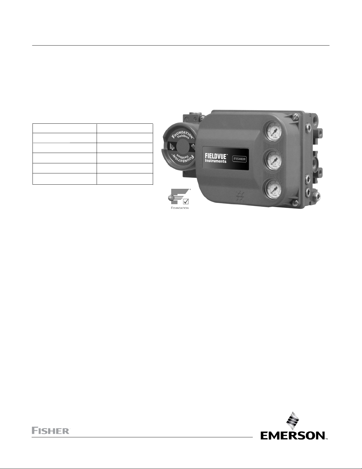
DVC6200f Digital Valve Controller
Fisher™ FIELDVUE™ DVC6200f Digital Valve
May 2022
Controller for F
This manual applies to:
Device Type 4602
Device Revision 4
Hardware Revision 8, 9
Firmware Revision 3.1
DD Revision 3
Instrument Level FD, PD, AD, PST
OUNDATION
™
Fieldbus
www.Fisher.com
1

DVC6200f Digital Valve Controller
May 2022
Instruction Manual
D103412X012
2

Instruction Manual
D103412X012
DVC6200f Digital Valve Controller
May 2022
Contents
Section 1 Introduction and
Specifications 5......................
Installation, Pneumatic and Electrical Connections,
and Initial Configuration 5.....................
Scope of Manual 5..............................
Instrument Description 5........................
Using this Manual 4.............................
Specifications 8................................
Related Information 12..........................
Educational Services 12..........................
Section 2 Wiring Practices 13.............
Quick Connect Cable Entry 13....................
Communication Connections 14..................
Simulate Enable Jumper 15.......................
Section 3 Basic Setup 17.................
Basic Setup 17.................................
Transducer Block Mode 17......................
Protection 17.................................
Device Setup 18...............................
Performance Tuner 22.........................
Section 4 Detailed Setup 23..............
Resource Block 23..............................
Configure/Setup 23.............................
Resource Block Mode 23.......................
Write Lock 23.................................
Communication Timeout 24....................
Options 24...................................
Alarm Handling 25............................
Identification 26..............................
Version 27...................................
Alert Handling 27.............................
Parameters Affected by Restart with Defaults 28.....
Resoure Block Parameter List 33..................
View Lists 45...................................
Transducer Block 47............................
Detailed Setup 47..............................
Transducer Block Mode 47......................
Protection 47.................................
Response Control 48...........................
Travel Tuning 48...........................
Pressure Tuning 50........................
Travel Pressure Control 51..................
Characterization 53........................
Custom Characterization Table 53............
Output Block Selection 54...................
Alerts 54......................................
Instrument Alert Conditions 54..................
Field Diagnostic Alerts 54.......................
Field Diagnostic Alert Category 55............
Alerts 55.....................................
Electronic Alerts 55........................
Configuration Alerts 57.....................
Sensor Alerts 58...........................
Environment Alerts 59......................
Travel Alerts 60............................
Proximity Alerts 61.........................
Travel History Alerts 62.....................
Performance Alerts 65......................
FST/PST Alerts 65..........................
Alert Handling 67.............................
Instrument 68................................
Valve and Actuator 69..........................
MAI Channel Map 72...........................
FST/PST 72...................................
Latch 78.....................................
Transducer Block Parameter List 79................
View Lists 114..................................
Section 5 Calibration 119................
Calibration Overview 119........................
Calibration 119.................................
Auto 120.....................................
Manual 120..................................
Relay 121....................................
Supply Pressure Sensor 122.....................
Pressure A or B Sensor 123......................
PST Calibration 124............................
Section 6 Viewing Device
Variables and Diagnostics 125..........
View Lists 125..................................
Resource Block 125.............................
Device Diagnostics 125.........................
Device Variables 129...........................
Transducer Block 131...........................
Device Diagnostics 131.........................
Device Variables 134...........................
Section 7 Maintenance and
Troubleshooting 137..................
Replacing the Magnetic Feedback Assembly 138.....
Module Base Maintenance 138....................
Tools Required 138............................
Component Replacement 139...................
Removing the Module Base 139.................
Replacing the Module Base 140..................
Submodule Maintenance 141.....................
I/P Converter 141..............................
Printed Wiring Board (PWB) Assembly 143.........
Pneumatic Relay 144...........................
Gauges, Pipe Plugs or Tire Valves 145.............
Terminal Box 145...............................
Removing the Terminal Box 145.................
Replacing the Terminal Box 146..................
Stroking the Digital Valve Controller Output 146.....
Instrument Troubleshooting 147..................
Technical Support Checklist 152..................
3

DVC6200f Digital Valve Controller
May 2022
Instruction Manual
D103412X012
Section 8 Parts 153.....................
Parts Ordering 153..............................
Parts Kits 153..................................
Parts List 154..................................
Housing 154..................................
Common Parts 154............................
Module Base 155..............................
I/P Converter Assembly 155.....................
Relay 155....................................
Terminal Box 155..............................
PWB Assembly 156............................
Pressure Gauges, Pipe Plugs, or
Tire Valve Assemblies 156....................
DVC6215 Feedback Unit 156....................
Appendix A Principle of Operation 163.....
Digital Valve Controller Operation 163.............
Appendix B Device Communicator
Menu Tree 165.......................
Appendix C Field Diagnostic Alerts 183.....
Instrument Alert Conditions 183..................
Field Diagnostic Alerts 183......................
Alert Handling 184............................
Alert Reporting 185............................
Field Diagnostic Alerts Set Block Status 185........
Setting Field Diagnostic Alerts 186................
Using Field Diagnostic Alerts 190..................
Appendix D FOUNDATION Fieldbus
Communication 197..................
Function Block Overview 197.....................
Function Blocks 197...........................
Instrument Specific Blocks 198..................
Resource Blocks 198...........................
Transducer Blocks 198.........................
Block Modes 199...............................
Explanation of Modes 200......................
Examples of Modes for Various
Operation Statuses 201......................
Device Descriptions 201.........................
Transducer Block Status and Limit Propagation 201..
Status Propagation 202........................
Limit Propagation 202..........................
Network Communication 203....................
Device Addressing 203.........................
Link Active Scheduler 203.......................
Device Communications 204....................
Scheduled Transfers 204....................
Unscheduled Transfers 205..................
Function Block Scheduling 206..................
Network Management 206.......................
Appendix E Function Blocks 207...........
Analog Output Function Block 209................
Proportional/Integral/Derivative
Function Block 223...........................
Control Selector Function Block 243...............
Input Selector Function Block 255.................
Output Splitter Function Block 271................
Analog Input Function Block 283..................
Mulitple Analog Input Function Block 295..........
Discrete Output Function Block 301...............
Discrete Input Function Block 315.................
Appendix F Device Description
Installation 327......................
Overview 327..................................
Device Descriptions and Methods 328.............
Installing DD on a DeltaV
ProfessionalPLUS Workstation 328................
Installing DDs on Other Fieldbus Host Systems 330...
Displaying the Device Description Revision 331......
Glossary 333...........................
Index 337.............................
4

DVC6200f Digital Valve Controller
Instruction Manual
D103412X012
Introduction and Specifications
Section 1 Introduction and Specifications
Installation, Pneumatic and Electrical Connections,
and Initial Configuration
May 2022
Refer to the DVC6200 Series Quick Start Guide (D103556X012) for DVC6200f
installation, connection, and initial configuration information. If a copy of this quick
start guide is needed contact your Emerson sales office
or visit our website at Fisher.com.
Scan or click
to access
field support
Scope of Manual
This instruction manual is a supplement to the quick start guide that ships with every instrument. This instruction
manual includes product specifications, supplementary installation information, reference materials, custom setup
information, maintenance procedures, and replacement part details for the DVC6200f digital valve controller.
Note
All references to the DVC6200f digital valve controller include the DVC6205f base unit unless otherwise indicated.
This manual describes device setup using an Emerson Device Communicator. For information on using Fisher
ValveLink
™
software with the instrument, refer to the appropriate user guide or help.
Do not install, operate, or maintain a DVC6200f digital valve controller without being fully trained and
qualified in valve, actuator, and accessory installation, operation, and maintenance. To avoid personal
injury or property damage, it is important to carefully read, understand, and follow all of the contents
of this manual, including all safety cautions and warnings. If you have any questions about these
instructions contact your Emerson sales office
before proceeding.
Instrument Description
DVC6200f digital valve controllers for FOUNDATION Fieldbus are communicating, microprocessor‐based instruments. In
addition to the traditional function of converting a digital signal to a pneumatic output pressure, the DVC6200f digital
valve controller, using F
process operation as well as process control. This can be done using a DeltaV console, another F
system console, or with ValveLink software version 13 or later.
Using a compatible fieldbus configuration device, you can obtain information about the health of the instrument, the
actuator, and the valve. You can also obtain asset information about the actuator or valve manufacturer, model, and
serial number. You can set input and output configuration parameters and calibrate the instrument.
Using the F
OUNDATION Fieldbus protocol, information from the instrument can be integrated into control systems.
OUNDATION Fieldbus communications protocol, gives easy access to information critical to
OUNDATION Fieldbus
5
DVC6200f Digital Valve Controller
Introduction and Specifications
May 2022
Instruction Manual
D103412X012
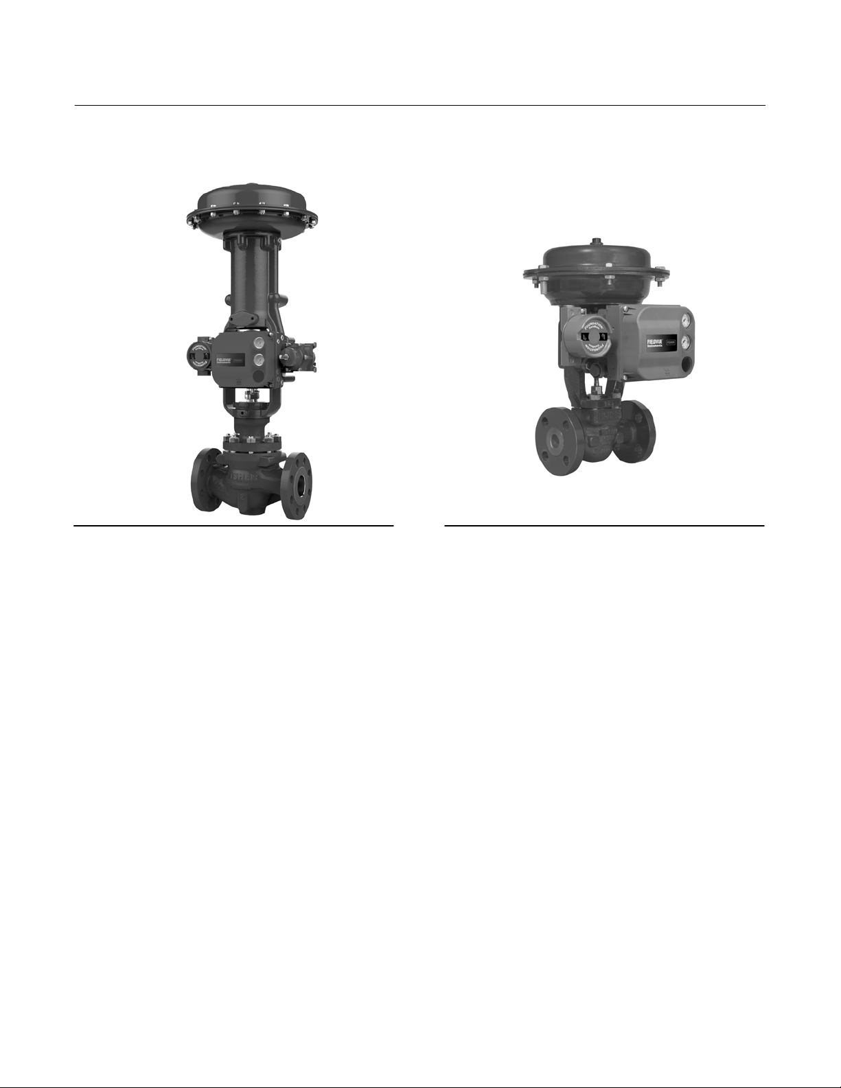
Figure 1‐1 FIELDVUE DVC6200f Digital Valve
Controller Mounted on a Fisher Sliding‐Stem Valve
Actuator
X1182-1_fieldbus
Figure 1‐2. FIELDVUE DVC6200f Digital Valve
Controller Integrally Mounted to a Fisher GX Control
Valve and Actuator System
W9616_fieldbus
DVC6200f digital valve controllers can be mounted on single or double‐acting sliding‐stem actuators, as shown in
figure 1‐1, or on rotary actuators. It can also be integrally mounted to Fisher 657/667 size 30i to 76i actuators or the
Fisher GX control valve and actuator system, as shown in figure 1‐2. The DVC6200f mounts on most Fisher and other
manufacturers' rotary and sliding‐stem actuators.
DVC6200f digital valve controllers are available with several selections of control and diagnostic capability. Control
selections include:
Standard Control (SC)— Digital valve controllers with Standard Control have the AO, PID, CSEL, ISEL, OS, AI, MAI,
DO, and four DI function blocks in addition to the resource and transducer blocks.
Fieldbus Control (FC)—Digital valve controllers with Fieldbus Control have the AO function block in addition to the
resource and transducer blocks.
Fieldbus Logic (FL)—Digital valve controllers with Fieldbus Logic have the DO, and four DI function blocks, in
addition to the resource and transducer block.
The diagnostic capabilities include:
Partial Stroke Test (PST)
Performance Diagnostics (PD)
Advanced Diagnostics (AD)
Fieldbus Diagnostics (FD)
Partial Stroke Test, Performance, and Advanced Diagnostics are available with ValveLink software. They provide
visibility to instrument alerts. Fieldbus Diagnostics can be viewed with any host system.
6

DVC6200f Digital Valve Controller
Instruction Manual
D103412X012
Introduction and Specifications
May 2022
Instrument Blocks
The digital valve controller is a block‐based device. For detailed information on the blocks within the digital valve
controller, see the Detailed Setup section of this manual.
The DVC6200f digital valve controller includes the resource and transducer block:
Resource Block—The resource block contains the hardware specific characteristics associated with a device; it has
no input or output parameters. The resource block monitors and controls the general operation of other blocks
within the device. For example, when the mode of the resource block is Out of Service, it impacts all function
blocks.
Transducer Block—The transducer block connects the analog output function block to the I/P converter, relay, and
travel sensor hardware within the digital valve controller.
Function Blocks
In addition to the resource and transducer block, the digital valve controller may contain the following function blocks,
Refer to Appendix E, Function Blocks ,for block specific information. For additional information on function blocks,
refer to Appendix D, F
OUNDATION fieldbus Communication.
Analog Output (AO) Function Block—The analog output function block accepts the output from another function
block (such as a PID block) and transfers it as an actuator control signal to the transducer block. If the DO block is
selected, the AO block is not functional.
Proportional‐Integral‐Derivative (PID) Function Block—The PID function block performs
proportional‐plus‐integral‐plus‐derivative control.
Control Select (CSEL) Function Block— The control select function block selects from two or three control signals in
a manner determined by the SEL_TYPE when the block is in Auto mode.
Input Selector (ISEL) Function Block—The input selector function block selects from up to four inputs and may
provide the selected signal as input to the PID block. The input selection can be configured to select the first good
input signal; a maximum, minimum or average value; or a hot spare.
Output Splitter (OS) Function Block—The output splitter function block accepts the output from another function
block (such as a PID block) and creates two outputs that are scaled or split, according to the user configuration. This
block is typically used for split ranging of two control valves.
Analog Input (AI) Function Block—The analog input function block monitors the signal from a DVC6200f sensor or
internal measurement and provides it to another block.
Multiple Analog Input (MAI) Function Block—The Multiple Analog Input (MAI) function block has the ability to
process up to eight DVC6200f measurements and make them available to other function blocks.
Discrete Output (DO) Function Block—The discrete output function block processes a discrete set point and sends it
to a specified output channel, which can be transferred to the transducer block for actuator control. In the digital
valve controller, the discrete output block provides both normal open/closed control and the ability to position the
valve in 5% increments for course throttling applications. If the AO block is selected, the DO block is not functional.
Discrete Input (DI) Function Block—The discrete input function block processes a single discrete input from a
DVC6200f and makes it available to other function blocks. In the digital valve controller, the discrete input function
block can provide limit switch functionality and valve position proximity detection.
7

DVC6200f Digital Valve Controller
Introduction and Specifications
May 2022
Instruction Manual
D103412X012
Using This Manual
Navigation paths and fast‐key sequences are included for procedures and parameters that can be accessed using a
Device Communicator.
For example, to access Resource Block Mode:
Device Communicator RB > Configure/Setup > Setup > Resource Block Mode
An overview of the resource and transducer block menu structures are shown in Appendix B. Menu structures for the
function blocks are included with each function block section in Detailed Setup.
Throughout this document, parameters are typically referred to by their common name or label, followed by the
parameter name and index number; for example, Write Priority (WRITE_PRI [39]). However, not all interface systems
support the use of the parameter label and instead use only the Parameter Name, followed by the index number, when
referring to the block parameters.
Specifications
Specifications for the DVC6200f digital valve controller are shown in table 1‐1.
8

Instruction Manual
D103412X012
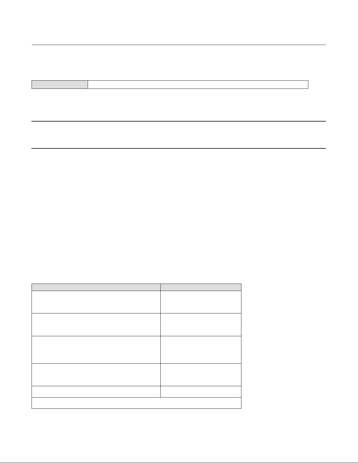
Table 1‐1. Specifications
DVC6200f Digital Valve Controller
Introduction and Specifications
May 2022
Available Mounting
DVC6200f digital valve controller and DVC6215
feedback unit:
GX actuators
actuators,
Quarter‐turn rotary applications
Integral mounting to 657/667 or
Integral mounting to Fisher rotary
Sliding‐stem linear applications
DVC6205f base unit for 2 inch pipestand or wall
mounting (for remote-mount)
The DVC6200f digital valve controller or DVC6215
feedback unit can also be mounted on other
actuators that comply with IEC 60534-6-1, IEC
60534-6-2, VDI/VDE 3845 and NAMUR mounting
standards.
Instrument Blocks
Resource Block
Transducer Block complies with F
OUNDATION Fieldbus
specification FF-906 for valve stroke testing
Function Block Suites
Standard Control (throttling control)
Includes AO, PID, CSEL, ISEL, OS, AI, MAI, DO,
and DI function block
Fieldbus Control (throttling control)
Contains the AO function block
Fieldbus Logic [discrete (on/off) connectivity]
Includes DO, and DI function blocks
Function Block
Instantiation
If a host system supports block instantiation, a
maximum of 20 function blocks can be instantiated in
the device at any given time from the available
function blocks, which may include AO (1), DO (1), AI
(4), DI (6), MAI (1), PID (4), OS (3), ISEL (2), CSEL (2)
Note: Only the function blocks available in the
function block suite can be instantiated by the host
system
Block Execution Times
Electrical Input
Voltage Level: 9 to 32 volts
Maximum Current: 19 mA
Reverse Polarity Protection: Unit is not polarity
sensitive
Termination: Bus must be properly terminated per
ISA SP50 guidelines
Digital Communication Protocol
F
OUNDATION fieldbus registered device
Physical Layer Type(s):
121—Low-power signaling, bus‐powered,
Entity Model I.S.
511—Low-power signaling, bus‐powered, FISCO I.S.
Fieldbus Device Capabilities
Backup Link Master capable
Supply Pressure
(1)
Minimum Recommended: 0.3 bar (5 psig) higher
than maximum actuator requirements
Maximum: 10.0 bar (145 psig) or maximum pressure
rating of the actuator, whichever is lower
Medium: Air or Natural Gas
Supply medium must be clean, dry and noncorrosive
Per ISA Standard 7.0.01
A maximum 40 micrometer particle size in the air
system is acceptable. Further filtration down to
5 micrometer particle size is recommended.
Lubricant content is not to exceed 1 ppm weight
(w/w) or volume (v/v) basis. Condensation in the air
supply should be minimized.
Per ISO 8573-1
Maximum particle density size: Class 7
Oil content: Class 3
Pressure Dew Point: Class 3 or at least 10C less than
the lowest ambient temperature expected
AO Block: 20 ms MAI BLock: 35 ms
PID Block: 20 ms DO Block: 20 ms
ISEL Block: 20 ms DI Block: 15 ms
OS Block: 20 ms CSEL Block: 15 ms
AI Block: 20 ms
-continued-
Output Signal
Pneumatic signal, up to full supply pressure
Minimum Span: 0.4 bar (6 psig)
Maximum Span: 9.5 bar (140 psig)
Action:
Double, Single Direct or Reverse
9

DVC6200f Digital Valve Controller
Introduction and Specifications
May 2022
Table 1‐1. Specifications (continued)
Instruction Manual
D103412X012
Steady-State Air Consumption
(2)(3)
Standard Relay
At 1.4 bar (20 psig) supply pressure:
Less than 0.38 normal m
At 5.5 bar (80 psig) supply pressure:
Less than 1.3 normal m
3
/hr (14 scfh)
3
/hr (49 scfh)
Low Bleed Relay
At 1.4 bar (20 psig) supply pressure:
Average value 0.056 normal m
At 5.5 bar (80 psig) supply pressure:
Average value 0.184 normal m
Maximum Output Capacity
At 1.4 bar (20 psig) supply pressure:
10.0 normal m
At 5.5 bar (80 psig) supply pressure:
29.5 normal m
3
/hr (375 scfh)
3
/hr (1100 scfh)
Operating Ambient Temperature Limits
3
/hr (2.1 scfh)
3
/hr (6.9 scfh)
(2)(3)
(1)(4)
-40 to 85C (-40 to 185F)
-52 to 85C (-62 to 185F) for instruments utilizing
the Extreme Temperature option (fluorosilicone
elastomers)
-52 to 125C (-62 to 257F) for remote‐mount
feedback unit
Independent Linearity
(5)
Typical Value: ±0.50% of output span
Electromagnetic Compatibility
Meets EN 61326-1:2013
Immunity—Industrial locations per Table 2 of
the EN 61326-1 standard. Performance is
shown in table 1‐2 below.
Emissions—Class A
ISM equipment rating: Group 1, Class A
Lightning and Surge Protection—The degree of
immunity to lightning is specified as Surge immunity
in table 1‐2. For additional surge protection
commercially available transient protection devices
can be used.
Vibration Testing Method
Tested per ANSI/ISA‐75.13.01 Section 5.3.5. A
resonant frequency search is performed on all three
axes. The instrument is subjected to the ISA specified
1/2 hour endurance test at each major resonance.
Humidity Testing Method
Tested per IEC 61514-2
Electrical Classification
Hazardous Area Approvals
CSA— Intrinsically Safe, FISCO, Explosion‐proof,
Division 2, Dust Ignition‐proof
FM— Intrinsically Safe, FISCO, Explosion‐proof,
Non‐Incendive, Dust Ignition‐proof
ATEX— Intrinsically Safe, FISCO, Flameproof, Type n,
Dust by intrinsic safety
IECEx— Intrinsically Safe, FISCO, Flameproof, Type n,
Dust by intrinsic safety or by enclosure
Electrical Housing
CSA— Type 4X, IP66
FM— Type 4X, IP66
ATEX— IP66
IECEx— IP66
Other Classifications/Certifications
Natural Gas Certified, Single Seal Device— CSA, FM,
ATEX, and IECEx
Lloyds Register— Marine Type Approval
CCC— China Compulsory Certification
CML— Certification Management Limited (Japan)
CUTR— Customs Union Technical Regulations
(Russia, Kazakhstan, Belarus, and Armenia)
DNV— Marine Type Approval
ESMA— Emirates Authority for Standardization and
Metrology - ECAS-Ex (UAE)
INMETRO— National Institute of Metrology, Quality
and Technology (Brazil)
KOSHA— Korean Occupational Safety & Health
Agency (South Korea)
KTL— Korea Testing Laboratory (South Korea)
NEPSI— National Supervision and Inspection Centre
for Explosion Protection and Safety of
Instrumentation (China)
PESO CCOE— Petroleum and Explosives Safety
Organisation - Chief Controller of Explosives (India)
SANS— South Africa National Standards
Contact your Emerson sales office
for
classification/certification specific information
10
-continued-

Instruction Manual
D103412X012
Table 1‐1. Specifications (continued)
DVC6200f Digital Valve Controller
Introduction and Specifications
May 2022
Connections
Supply Pressure: 1/4 NPT internal and integral pad for
mounting 67CFR regulator
Output Pressure: 1/4 NPT internal
Tubing: 3/8‐inch recommended
Optional: Stainless steel
Cover: Thermoplastic polyester
Elastomers
Standard: Nitrile
Extreme Temperature: Fluorosilicone
Vent: 3/8 NPT internal
Electrical: 1/2 NPT internal or M20
Actuator Compatibility
Sliding‐Stem Linear
Linear actuators with rated travel between 6.35 mm
(0.25 inch) and 606 mm (23.375 inches)
Quarter‐Turn Rotary
Rotary actuators with rated travel between
45 degrees and 180 degrees
(6)
Weight
DVC6200f
Aluminum: 3.5 kg (7.7 lbs)
Stainless Steel: 8.6 kg (19 lbs)
DVC6205f: 4.1 kg (9 lbs)
DVC6215: 1.4 kg (3.1 lbs)
Options
Supply and output pressure gauges or Tire
Integral mounted filter regulator
valves
Low‐Bleed Relay
(7)
Extreme Temperature
Natural Gas Certified, Single Seal Device Remote
(8)
Mount
Contact your Emerson sales office
Stainless Steel
or go to Fisher.com
for additional information.
Declaration of SEP
Fisher Controls International LLC declares this
product to be in compliance with Article 4 paragraph
3 of the PED Directive 2014/68/EU. It was designed
and manufactured in accordance with Sound
Engineering Practice (SEP) and cannot bear the CE
marking related to PED compliance.
Construction Materials
Housing, module base and terminal box
Standard: A03600 low copper aluminum alloy
NOTE: Specialized instrument terms are defined in ANSI/ISA Standard 51.1 - Process Instrument Terminology.
1. The pressure/temperature limits in this document and any other applicable code or standard should not be exceeded.
2. Normal m
3. Values at 1.4 bar (20 psig) based on a single-acting direct relay; values at 5.5 bar (80 psig) based on double-acting relay.
4. Temperature limits vary based on hazardous area approval. Lower temperature limit for CUTR Ex d approval with fluorosilicone elastomers is -53C (-63.4F).
5. Not applicable for travels less than 19 mm (0.75 inch) or for shaft rotation less than 60 degrees. Also not applicable for digital valve controllers in long-stroke applications.
6. Rotary actuators with 180 degree rated travel require a special mounting kit; contact your Emerson sales office for kit availability
7. The Quad O steady-state consumption requirement of 6 scfh can be met by a DVC6200f with low bleed relay A option, when used with up to 4.8 bar (70 psi) supply of
Natural Gas at 16C (60F). The 6 scfh requirement can be met by low bleed relay B and C when used with up to 5.2 bar (75 psi) supply of Natural Gas at 16C (60F).
8. 4‐conductor shielded cable, 18 to 22 AWG minimum wire size, in rigid or flexible metal conduit, is required for connection between base unit and feedback unit. Pneumat
ic tubing between base unit output connection and actuator has been tested to 91 meters (300 feet). At 15 meters (50 feet) there was no performance degradation. At
91 meters there was minimal pneumatic lag.
3
/hour - Normal cubic meters per hour at 0C and 1.01325 bar, absolute. Scfh - Standard cubic feet per hour at 60F and 14.7 psia.
However, the product may bear the CE marking to
indicate compliance with other applicable European
Community Directives.
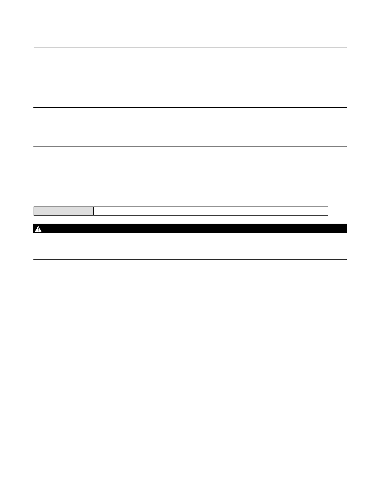
Table 1‐2. EMC Summary Results—Immunity
Port Phenomenon Basic Standard Test Level
Electrostatic discharge (ESD) IEC 61000‐4‐2
Enclosure
I/O signal/control
Performance criteria: +/- 1% effect.
1. A = No degradation during testing. B = Temporary degradation during testing, but is self‐recovering.
2. Excluding Simulate function, which meets Performance Criteria B.
Radiated EM field IEC 61000‐4‐3
Rated power frequency
magnetic field
Burst IEC 61000‐4‐4
Surge IEC 61000‐4‐5
Conducted RF IEC 61000‐4‐6
IEC 61000‐4‐8
4 kV contact
8 kV air
80 to 1000 MHz @ 10V/m with 1 kHz AM at 80%
1400 to 2000 MHz @ 3V/m with 1 kHz AM at 80%
2000 to 2700 MHz @ 1V/m with 1 kHz AM at 80%
30 A/m at 50/60 Hz
1 kV
1 kV
150 kHz to 80 MHz at 3 Vrms
Performance
Criteria
(2)
A
A
A
(2)
A
B
A
(1)
11

DVC6200f Digital Valve Controller
Introduction and Specifications
May 2022
Instruction Manual
D103412X012
Related Information
Fieldbus Installation and Wiring Guidelines
This manual describes how to connect the fieldbus to the digital valve controller. For a technical description, planning,
and installation information for F
Fieldbus Foundation and Fieldbus Installations in a DeltaV System, available from your Emerson sales office
Related Documents
Other documents containing information related to the DVC6200f digital valve controller include:
OUNDATION Fieldbus, refer to the Foundation Technology Overview, available from the
.
Bulletin 62.1:DVC6200f - DVC6200f Digital Valve Controller (D103399X012
Bulletin 62.1:DVC6200f FD - DVC6200f Digital Valve Controller (D103422X012
Bulletin 62.1:DVC6200f PST - DVC6200f Digital Valve Controller - PST Instrument Level (D104160X012
Bulletin 62.1:DVC6200(S1) - DVC6200 Digital Valve Controller Dimensions (D103543X012
Bulletin 62.1:Digital Valve Controller - Fisher FIELDVUE Digital Valve Controller Product Selection (D104363X012
FIELDVUE DVC6200 Series Quick Start Guide (D103556X012
CSA Hazardous Area Approvals - DVC6200 Series Digital Valve Controllers (D104203X012
FM Hazardous Area Approvals - DVC6200 Series Digital Valve Controllers (D104204X012
ATEX Hazardous Area Approvals - DVC6200 Series Digital Valve Controllers (D104205X012
IECEx Hazardous Area Approvals - DVC6200 Series Digital Valve Controllers (D104206X012
DVC6200f Digital Valve Controller PST Calibration and Testing using ValveLink Software (D104217X012
™
AMS Trex
ValveLink Software Help or Documentation
Device Communicator User Guide
)
)
)
)
)
)
)
)
)
)
)
All documents are available from your Emerson sales office or at Fisher.com.
Educational Services
For information on available courses for the DVC6200f digital valve controller, as well as a variety of other products,
contact:
Emerson Automation Solutions
Educational Services - Registration
Phone: +1-641-754-3771 or +1-800-338-8158
e‐mail: education@emerson.com
emerson.com/fishervalvetraining
12
DVC6200f Digital Valve Controller
Instruction Manual
D103412X012
Installation Information
May 2022
Section 2 Wiring Practices 2-2-
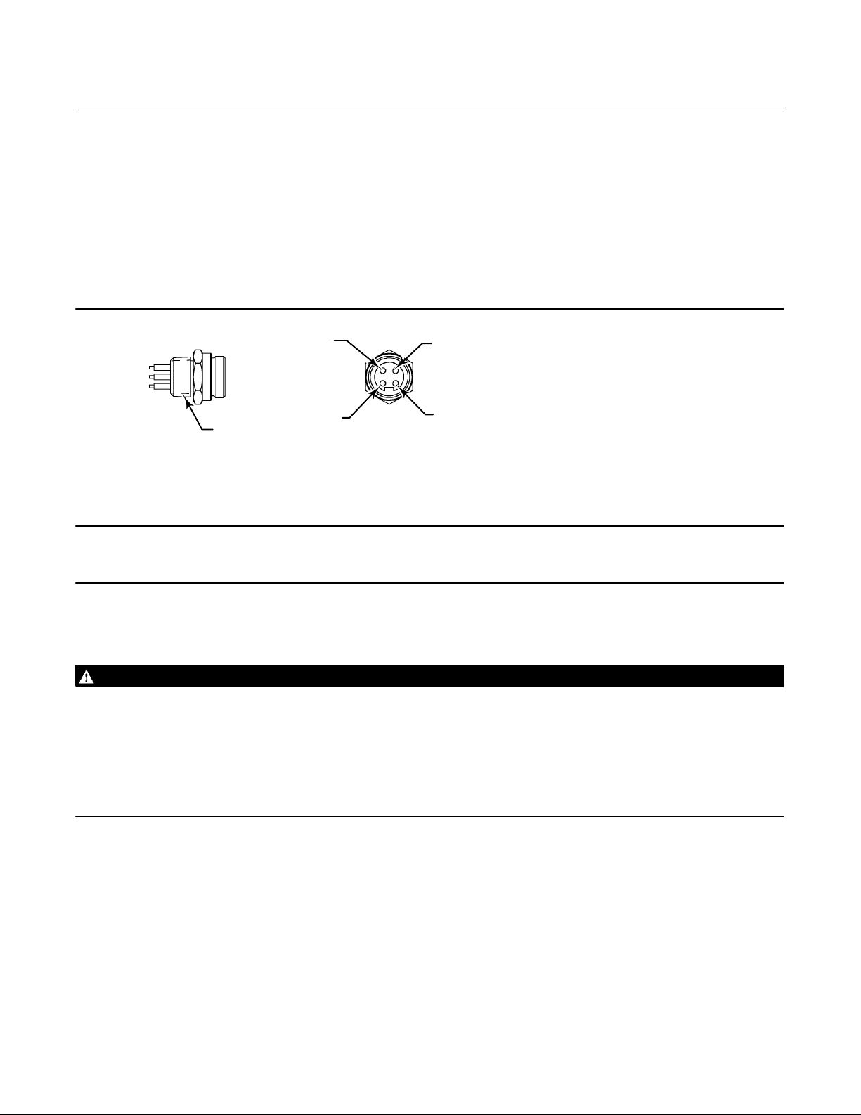
Quick Connect Cable Entry
The DVC6200f is offered with a quick connect cable entry option, shown in figure 2‐1, for the FOUNDATION Fieldbus
signal. The quick connect cable entry provides an easier and more reliable interface to fieldbus devices and support
modules by providing a standard connection.
Figure 2‐1. Quick Connect Connector
1 (BLUE)
3 (NC)
2 (BROWN)
1/2‐14 NPT
NOTES:
1. COLORS ARE WIRE COLORS.
2. NC=NO CONNECTION.
18B9424‐A
Note
The quick connect cable entry option is only available for intrinsically safe and non‐incendive installations.
4 (GREEN/YELLOW)
Refer to figure 8‐2 for identification of parts.
WARNING
Personal injury or property damage, caused by fire or explosion, can result from the discharge of static electricity. Connect
a 14 AWG (2.08 mm
gases are present. Refer to national and local codes and standards for grounding requirements.
To avoid static discharge from the plastic cover, do not rub or clean the cover with solvents. Clean with a mild detergent
and water only.
To avoid personal injury or property damage, do not use the Quick Connect option on instruments in explosion‐proof or
flameproof installations.
2
) ground strap between the digital valve controller and earth ground when flammable or hazardous
1. The quick connect cable entry should be installed on the digital valve controller at the factory. If it is, proceed to
step 3. If not continue with step 2.
2. To install the Quick Connect:
a. Remove the terminal box cap (key 4) from the terminal box (key 3).
b. Apply sealant to the threads of the quick connector.
c. Insert the wire pigtail into the desired conduit opening on the terminal box. Tighten the quick connector in the
conduit opening.
13

DVC6200f Digital Valve Controller
Installation Information
May 2022
Instruction Manual
D103412X012
d. The instrument is not polarity sensitive. Refer to figure 2‐2. Connect the blue wire to the negative (-) LOOP
terminals in the terminal box. Connect the brown wire to the positive (+) LOOP terminal. Isolate the green/yellow
wire inside of the DVC6200f and ensure that the shield is totally isolated at the instrument end.
Note
The green/yellow wire is isolated inside the DVC6200f to help prevent ground loop issues.
e. Replace the terminal box cap on the terminal box and tighten until no gap remains. Secure the terminal box cap
by engaging the lock screw.
3. Connect the field wiring connector to the installed quick connector.
Figure 2‐2. Loop Connections Terminal Box
SAFETY
GROUND
GE41456-A
TALK
TALK
EARTH
GROUND
LOOP
LOOP
Communication Connections
WARNING
Personal injury or property damage caused by fire or explosion may occur if this connection is attempted in a potentially
explosive atmosphere or in an area that has been classified as hazardous. Confirm that area classification and atmosphere
conditions permit the safe removal of the terminal box cap before proceeding.
A FOUNDATION Fieldbus communicating device, such as an Emerson Device Communicator or a personal computer
running ValveLink software, interfaces with the DVC6200f digital valve controller from any wiring termination point in
the segment. If you choose to connect the fieldbus communicating device directly to the instrument, attach the
device to the LOCAL connections inside the terminal box to provide local communications with the instrument.
14

DVC6200f Digital Valve Controller
Instruction Manual
D103412X012
Installation Information
May 2022
Simulate Enable Jumper
WARNING
Personal injury or property damage caused by fire or explosion may occur if this connection is attempted in a potentially
explosive atmosphere or in an area that has been classified as hazardous. Confirm that area classification and atmosphere
conditions permit the safe removal of the terminal box cap before proceeding.
Install a jumper across the SIMULATE ENABLE terminals to enable the instrument to accept a simulate command.
(These terminals are marked AUX on the terminal board, see figure 2‐2). With the jumper in place and the simulate
parameter in the AO or DO block set to enabled, the transducer block ignores the output of the AO or DO block. The
simulate value and status become the readback value and status to the AO or DO block and the transducer block is
ignored. For more information on running simulations, see the Detailed Setup section of this manual, the
Fieldbus specifications, and the host documentation.
WARNING
Removing the jumper will disable the simulate, which may cause the valve to move. To avoid personal injury and property
damage caused by the release of pressure or process fluid, provide some temporary means of control for the process.
FOUNDATION
15

DVC6200f Digital Valve Controller
Installation Information
May 2022
Instruction Manual
D103412X012
16
DVC6200f Digital Valve Controller
Instruction Manual
D103412X012
Basic Setup
May 2022
Section 3 Basic Setup3-3-
Basic Setup
Device Communicator TB > Configure/Setup > Basic Setup
WARNING
Changes to the instrument setup may cause changes in the output pressure or valve travel. Depending on the application,
these changes may upset process control, which may result in personal injury or property damage.
When the DVC6200f digital valve controller is ordered as part of a control valve assembly, the factory mounts the
digital valve controller and sets up the instrument as specified on the order. When mounting to a valve in the field, the
instrument needs to be setup to match the instrument to the valve and actuator.
Before beginning basic setup, be sure the instrument is correctly mounted as described in the Installation section.
Basic Setup includes the following procedures:
Device Setup
Performance Tuner (Optional)
Note
The DVC6200f may keep the Transducer Block Mode Out‐of‐Service if the instrument is not properly mounted.
To setup and calibrate the instrument, the Transducer Block Mode must be Manual, and the Protection must be None.
When using DD methods the method will request that you change the mode, but make changes in Protection automatically. If you
have a host system that overrides transducer block parameters ensure that the Protection setting is not
result in transducer block parameters being overwritten.
left as None. Doing so will
Transducer Block Mode
Device Communicator TB > Device Variables > TB Block Mode
To setup and calibrate the instrument, the transducer block mode must be in Manual. For more information about
transducer block mode, refer to page 47.
Protection
Device Communicator TB > Configure/Setup > Detailed Setup > Protection
To setup and calibrate the instrument, the protection must be set to None with the Device Communicator. For more
information about configuration protection refer to page 47.
17
DVC6200f Digital Valve Controller
Basic Setup
May 2022
Instruction Manual
D103412X012
Device Setup
Device Communicator TB > Configure/Setup > Basic Setup > Device Setup
Follow the prompts on the Device Communicator display to automatically setup the instrument using specified
actuator information. Table 3‐2 provides the actuator information required to setup and calibrate the instrument.
Note
If reverse‐acting relay B is used, you must manually set the Relay Type (BASIC_SETUP.RELAY_TYPE [42.5]) to B. This will not be set
during Device Setup.
1. Select whether Travel, Travel with Pressure fallback (auto recovery or manual recovery) or Pressure Control is
desired. Refer to page 51 for additional information.
2. Enter the pressure units: kPa, bar, psi, inHg, inH
3. Enter the maximum instrument supply pressure and output pressure range (if required).
4. Enter the manufacturer of the actuator on which the instrument is mounted. If the actuator manufacturer is not
listed, select Other.
5. Enter the actuator model or type. If the actuator model is not listed, select Other.
6. Enter the actuator size.
7. Indicate whether a Volume Booster is being used.
8. Specify if factory defaults should be used for basic setup. If you select YES for factory default, the Device
Communicator sets the setup parameters to the values listed in table 3‐1. If you select NO for the factory defaults,
the setup parameters listed in the table remain at their previous settings.
O, or kg/cm2.
2
Table 3‐1. Factory Default Settings
Setup Parameter
Travel Cutoff Hi
Travel Cutoff Lo
Travel Integral Gain
Travel Calibration Trigger
Travel Integral Enable
Travel Integral Limit Hi
Travel Integral Limit Lo
Travel Integral Deadzone
Pressure Cutoff Hi
Pressure Cutoff Lo
Pressure Integral Deadzone
Pressure Integral Hi Limit
Pressure Integral Lo Limit
Input Characterization
Shutdown Trigger
Shutdown Recovery
Output Block Timeout
STOP Hi Pos
STOP Lo Pos
1. For PST instruments, the PST prohibited configuration will be erased if the instrument is set to factory default
settings. These parameters will need to be re-configured if the PST prohibited configuration is desired.
18
(1)
99.5%
0.5%
9.4 repeats/min
No
On
30%
-30%
0.25%
99.5%
-0.5%
0.25%
50.0%
-50.0%
Linear
All Off
All Auto Recovery
600 sec
98%
2%
Default Setting
Instruction Manual
D103412X012
DVC6200f Digital Valve Controller
Basic Setup
May 2022
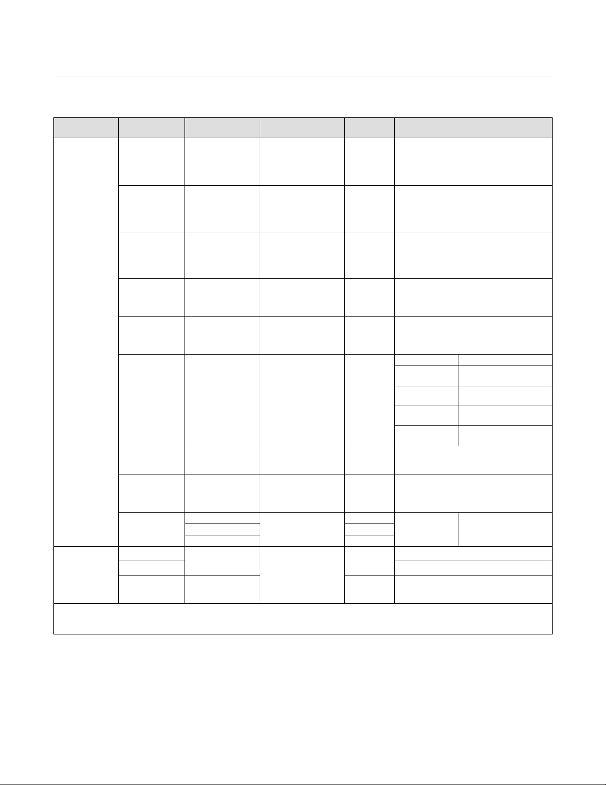
Table 3‐2. Actuator Information for Initial Setup
Actuator
Manufacturer
Fisher
Baumann
NOTE: Refer to table 4‐9 for feedback connection (magnet assembly) information.
1. X = Expert Tuning. Proportional Gain = 4.2; Velocity Gain = 3.0; Minor Loop Feedback Gain = 18.0
2. Travel Sensor Motion in this instance refers to the motion of the magnet assembly.
3. Values shown are for Relay A and C. Reverse for Relay B.
Actuator Model Actuator Size Actuator Style
25
585C & 585CR
657
667
1051 & 1052
1061
1066SR
2052
3024
GX
Air to Extend
Air to Retract Towards the top of the instrument
Rotary
50
60
68, 80
100, 130
30, 30i
34, 34i, 40, 40i
45, 45i, 50, 50i
46, 46i, 60, 60i, 70,
70i & 80‐100
30, 30i
34, 34i, 40, 40i
45, 45i, 50, 50i
46, 46i, 60, 60i, 70,
70i, 76, 76i & 80‐100
20, 30
33
40
60, 70
30
40
60
68, 80, 100, 130
20
27, 75
1
2
3
30, 30E
34, 34E, 40, 40E
45, 45E
225
750 K
1200 M
16
32
54
10
25
54
Piston Dbl w/ or w/o
Spring. See actuator
instruction manual and
nameplate.
Spring & Diaphragm
Spring & Diaphragm
Spring & Diaphragm
(Window-mount)
Piston Dbl w/o Spring
Piston Sgl w/Spring
Spring & Diaphragm
(Window-mount)
Spring & Diaphragm
Spring & Diaphragm
Spring & Diaphragm
Starting
Tuning Set
E
I
J
L
M
H
K
L
M
H
K
L
M
H
I
K
M
J
K
L
M
G
L
H
K
M
E
H
K
(1)
X
C
E
H
E
H
J
Travel Sensor Motion
Relay A or C
User Specified
Away from the top of the instrument
Towards the top of the instrument
Away from the top of the instrument
Depends upon pneumatic connections. See
description for Travel Sensor Motion
Mounting Style Travel Sensor Motion
A
B
C
D
Away from the top of the instrument
For Po operating mode (air opens):
Towards the top of the instrument
For P
operating mode (air closes):
s
Away from the top of the instrument
Air to Open
Towards the top
of the instrument
Away from the top of the instrument
Away from the top of the
Towards the top of the
Towards the top of the
Away from the top of the
Away from the top of the
Specify
(2)
(3)
instrument
instrument
instrument
instrument
Air to Close
instrument
19

DVC6200f Digital Valve Controller
Basic Setup
May 2022
Instruction Manual
D103412X012
Typically Device Setup determines the required setup information based upon the actuator manufacturer and model
specified. However, if you enter OTHER for the actuator manufacturer or the actuator model, then you will be
prompted for setup parameters such as:
Actuator Style—Select spring & diaphragm, piston double‐acting without spring, piston single‐acting with spring,
piston double‐acting with spring.
Valve Style—Select the valve style, rotary or sliding‐stem.
Zero Power Condition—this identifies whether the valve is fully open or fully closed when the input is 0%. If you are
unsure how to set this parameter, disconnect the instrument from the segment. (With double‐acting and
single‐acting direct digital valve controllers, disconnecting the instrument from the segment is the same as setting
the output A pressure to zero. For single‐acting reverse digital valve controllers, disconnecting the instrument from
the segment is the same as setting the output B pressure to supply.)
WARNING
If you answer YES to the prompt for permission to move the valve when setting the Travel Sensor Motion, the instrument
will move the valve through its full travel range. To avoid personal injury and property damage caused by the release of
pressure or process fluid, isolate the valve from the process and equalize pressure on both sides of the valve or bleed off the
process fluid.
Travel Sensor Motion—Device Setup asks if it can move the valve to determine travel sensor motion. If you answer
Yes, the instrument will stroke the valve the full travel span to determine travel sensor motion. If you answer No,
then you must specify the direction of travel movement. For quarter‐turn actuators determine rotation by viewing
the rotation of the magnet assembly from the back of the instrument.
Note
Travel Sensor Motion in this instance refers to the motion of the magnet assembly. Note that the magnet assembly may be
referred to as a magnetic array in user interface tools.
For instruments with relay A or C If increasing air pressure at output A causes the magnet assembly to move up, or
the actuator shaft to rotate counterclockwise, enter “Towards Top of Instrument/CCW.” If it causes the magnet
assembly to move down, or the actuator shaft to rotate clockwise, enter “Away From Top of Instrument/CW.” For
instruments with relay B.
For instruments with relay B If decreasing air pressure at output B causes the magnet assembly to move up, or the
actuator shaft to rotate counterclockwise, enter “Towards Top of Instrument/CCW.” If it causes the magnet
assembly to move down, or the actuator shaft to rotate clockwise, enter “Away From Top of Instrument/CW.”
Note
Relay A adjustment may be required before Device Setup can determine travel sensor motion. Follow the prompts on the Device
Communicator display if relay adjustment is necessary.
Table 3‐2 lists the required Travel Sensor Motion selections for Fisher and Baumann actuators.
20

DVC6200f Digital Valve Controller
Instruction Manual
D103412X012
Basic Setup
May 2022
Tuning Set—There are twelve tuning sets to choose from. Each tuning set provides a preselected value for the digital
valve controller gain settings. Tuning set C provides the slowest response and M provides the fastest response. For
smaller actuators use tuning set C or D. For larger actuators using tuning set F or G. Table 3‐3 lists the values for
preselected tuning sets.
Note
Tuning set B is only available in Pressure Control Mode.
Table 3‐3. Gain Values for Preselected Tuning Sets
Travel Pressure
Tuning Set
B
C
D
E
F
G
H
I
J
K
L
M
X (Expert) User Adjusted User Adjusted User Adjusted User Adjusted User Adjusted User Adjusted
Proportional Gain Velocity Gain
‐ ‐ ‐
4.4
4.8
5.5
6.2
7.2
8.4
9.7
11.3
13.1
15.5
18.0
‐ ‐ ‐
3.0
3.0
3.0
3.1
3.6
4.2
4.8
5.6
6.0
6.0
6.0
Minor Loop
Feedback Gain
‐ ‐ ‐
35
35
35
35
34
31
27
23
18
12
12
Proportional Gain Integrator Gain
0.5
2.2
2.4
2.8
3.1
3.6
4.2
4.8
5.6
6.6
7.8
9.0
0.3
0.1
0.1
0.1
0.1
0.1
0.1
0.1
0.1
0.1
0.1
0.1
Minor Loop
Feedback Gain
35
35
35
35
35
34
31
27
23
18
12
12
WARNING
Changes to the tuning set may cause the valve/actuator assembly to stroke. To avoid personal injury or property damage
caused by moving parts, keep hands, tools, and other objects away from the valve/actuator assembly.
In addition, you can select Expert, which allows you to individually set the proportional gain, velocity gain, and minor
loop feedback gain for travel tuning and pressure proportional gain, pressure integrator gain, and pressure minor loop
feedback gain for pressure tuning. Refer to page 48 for additional information on travel tuning and page 50 for
pressure tuning.
Note
Use Expert tuning only if standard tuning has not achieved the desired results.
Stabilize/Optimize or Performance Tuner may be used to achieve the desired results more rapidly than expert tuning.
Table 3‐2 provides tuning set selection guidelines for Fisher and Baumann actuators. These tuning sets are only
recommended starting points. After you finish setting up and calibrating the instrument, use Stabilize/Optimize to
adjust the tuning set to get the desired response.
21
DVC6200f Digital Valve Controller
Basic Setup
May 2022
Instruction Manual
D103412X012
When Device Setup is complete you are asked if you wish to run Auto Calibration now. Select yes to automatically
calibrate instrument travel at this time. Follow the prompts on the Device Communicator display. The calibration
procedure uses the valve and actuator stops as the 0% and 100% calibration points. For additional information, refer to
Auto Calibration in the Calibration section.
Note
Single‐acting relay B and C are not user‐adjustable. However, it is recommended that you check the relay adjustment for
double‐acting relay A in new installations before proceeding with travel calibration.
Refer to page 121 for relay adjustment instructions.
If after completing setup and calibration the valve cycles or overshoots (unstable), or is unresponsive (sluggish), you
can improve operation by running Performance Tuner or Stabilize/Optimize.
Performance Tuner
Device Communicator TB > Configure/Setup > Detailed Setup > Response Control > Travel Tuning > Performance Tuner
WARNING
During performance tuning the valve may move, causing process fluid or pressure to be released. To avoid personal injury
and property damage caused by the release of process fluid or pressure, isolate the valve from the process and equalize
pressure on both sides of the valve or bleed off the process fluid.
The Performance Tuner is used to determine digital valve controller tuning. It will move the valve slightly and monitor
the effects of small tuning changes until an optimum control response is achieved. Because the Performance Tuner
can detect internal instabilities before they become apparent in the travel response, it can generally optimize tuning
more effectively than manual tuning. Typically, the Performance Tuner takes 3 to 5 minutes to tune an instrument,
although tuning instruments mounted on larger actuators may take longer.
22

DVC6200f Digital Valve Controller
Instruction Manual
D103412X012
Detailed Setup - Resource Block
May 2022
Section 4 Detailed Setup 4-4-
Resource Block
The resource block contains the hardware specific characteristics associated with a device; it has no input or output
parameters. The resource block monitors and controls the general operation of other blocks within the device. Most of
the resource block parameters are operational parameters that provide information about the instrument such as
identification, hardware information, available options, etc. and are read only. Configuration of the resource block
involves selecting features from those that are available, setting the mode, setting write lock, and setting up alert
reporting details.
The following procedures address only the key resource block parameters; however, all resource block parameters are
listed in table 4‐2.
Configure/Setup
Device Communicator RB > Configure/Setup
Resource Block Mode
Modes
The resource block can be in one of two modes (MODE_BLK [5]):
Automatic (Auto) is the operational mode for this block. When the resource block is in the Auto mode, all other
function blocks are allowed to function normally.
Out of Service (OOS)—Placing the resource block in Out of Service mode stops all function block execution, by
setting their modes to Out of Service as well. The actual mode of the function blocks is changed to Out of Service, but
the function block target modes are retained. Placing the resource block in the Out of Service mode does not affect
the mode of the transducer block.
Write Lock
Write Lock (WRITE_LOCK [34]) determines if writes are permissible to other device parameters. The write lock feature
must be selected to be able to use Write Lock (see Features Available). When Write Lock is set to Locked, no writes are
permitted to any parameters within the device except to set Write Lock to Not Locked. When locked, the device
functions normally, updating inputs and outputs and executing algorithms. When Write Lock is set to Not Locked, the
Write Alarm (WRITE_ALM [40]) alert is active.
Write Priority (WRITE_PRI [39]) sets the priority for Write Alarm. The lowest priority is 0. The highest is 15.
23

DVC6200f Digital Valve Controller
Detailed Setup - Resource Block
May 2022
Instruction Manual
D103412X012
Communication Timeout
Shed Remote Cascade
Note
Typically this parameter does not need to be changed. The unit will be operational using the default values assigned by the factory.
Perform this procedure only if a remote computer is sending setpoints from your “advanced” control.
Default value for RCas Timeout is 20 seconds.
Shed Remote Cascade (SHED_RCAS [26]) determines how long function blocks in the DVC6200f should wait before
giving up on remote computer writes to RCas parameters. When the timeout is exceeded, the block sheds to the next
mode as defined by the block shed options. If Shed Remote Cascade is set to 0, the block will not shed from RCas.
Enter a positive value in the Shed Remote Cascade field. Time duration is in 1/32 milliseconds (640000
Shed Remote Out
= 20 secs).
Note
Typically this parameter does not need to be changed. The unit will be operational using the default values assigned by the factory.
Perform this procedure only if a remote computer is sending setpoints from your “advanced” control.
Default value for Shed Remote Out is 20 seconds.
Shed Remote Out (SHED_ROUT [27]) determine how long function blocks in the DVC6200f should wait before giving
up on computer writes to ROut parameters. When the timeout is exceeded, the block sheds to the next mode as
defined by the block shed options. If Shed Remote Out is set to 0, the block will not shed from ROut. Enter a positive
value in the Shed Remote Out field. Time duration is in 1/32 milliseconds (640000
= 20 secs).
Options
Diagnostic Tier (DIAG_OPTIONS [103]) show which diagnostic options are available in the instrument.
Function Block Options (FB_OPTIONS [102]) show which function blocks are available in the instrument.
Miscellaneous Options (MISC_OPTIONS [104]) indicate which miscellaneous licensing options are enabled.
Features Available (FEATURES [17]) indicates which feature options are available in the resource block.
Reports enables alert and event reporting. Reporting of specific alerts may be suppressed. See Alerts on page 54.
Fault State enables the ability of the output block to react to various abnormal conditions by shedding mode. See
parameter descriptions for Set Fault State (SET_FSTATE [29]) and Clear Fault State (CLR_FSTATE [30]) in table 4‐2
and “Action on Fault Detection”.
Write Lock permits using Write Lock (WRITE_LOCK [34]) to prevent any external change to parameter values. Block
connections and calculation results will proceed normally, but the configuration is locked. Also see Write Lock, on
page 23.
24

DVC6200f Digital Valve Controller
Instruction Manual
D103412X012
Detailed Setup - Resource Block
May 2022
Multi‐bit Alarm (Bit‐Alarm) Support permits the instrument to treat each Field Diagnostic alert separately when
broadcast to the Host. Without Multi‐Bit Alarm Support, an individual Field Diagnostic alert must be acknowledged
before another Field Diagnostic alert can be broadcast to the Host.
Features Selected
Note
Typically this parameter does not need to be changed. The unit will be operational using the default values assigned by the factory.
Fault State, Software Write Lock, and Output Readback are set by default.
Features Selected (FEATURE_SEL [18]) indicates which Resource Block Options features have been selected and is used
to select the desired features.
Reports—Selecting reports enables alert and event reporting. Reporting of specific alerts may be suppressed. See
Alerts on page 54.
Fault State—Selecting fault state enables the ability of the output block to react to various abnormal conditions by
shedding mode. See parameter descriptions for Set Fault State (SET_FSTATE [29]) and Clear Fault State
(CLR_FSTATE [30]) in table 4‐2 and “Action on Fault Detection”.
Soft Write Lock—When selected, permits using Write Lock (WRITE_LOCK [34]) to prevent any external change to
parameter values. Block connections and calculation results will proceed normally, but the configuration is locked.
Also see Write Lock, on page 23.
Multi‐bit Alarm (Bit‐Alarm) Support— When selected, the instrument will allow the instrument to treat each Field
Diagnostic alert separately when broadcast to the Host.
Alarm Handling
Alert Key (ALERT_KEY [4]) is a number that permits grouping alerts. This number may be used to indicate to the
operator the source of the alert, such as the instrument, plant unit, etc. Enter a value between 1 and 255.
Confirm Time (CONFIRM_TIME [33]) determines the time, in 1/32 of a millisecond, the instrument waits for
confirmation of receipt of a report before trying again. If Confirm Time is 0, the instrument does not retry to send the
report. Enter 0 or a value between 320000 (10 secs) and 640000 (20 secs).
Limit Notify (LIM_NOTIFY [32]) is the number of alert reports that the device can send without getting a confirmation
up to the maximum permitted in Maximum Notify (MAX_NOTIFY [31]). If Limit Notify is set to zero, no alerts are
reported. Enter a value between 0 and 4.
To have the instrument report alerts without having the host poll the alerts parameters, select the Reports feature (see
Feature Select).
Maximum Notify (MAX_NOTIFY [31]) indicates the maximum number of alert reports that the device can send without
getting a confirmation. This limit is determined by the amount of memory available for alert messages. The number
can be set lower, to control alert flooding, by adjusting Maximum Alerts Allowed (LIM_NOTIFY [32]).
Block Alarm Disabled The Block Alarm (BLOCK_ALM [36]) is used for all configuration, hardware, connection failure or
system problems in the block. Alarm Summary (ALARM_SUM [37]) determines if the Write Alarm (WRITE_ALM [40])
and Block Alarm [BLOCK_ALM [36]) are disabled.
25

DVC6200f Digital Valve Controller
Detailed Setup - Resource Block
May 2022
Block Alarm Auto Acknowledge (ACK_OPTION [38]) determines if the block alarm will be automatically
acknowledged.
Discrete Alarm Disabled The Write Alarm (WRITE_ALM [40]) is used to alert when parameters are writable to the
device. Alarm Summary (ALARM_SUM [37]) determines if the Discrete Alarm is disabled.
Discrete Alarm Auto Acknowledge (ACK_OPTION [38]) determines if the Write Alarm associated with the block will be
automatically acknowledged.
Instruction Manual
D103412X012
Identification
Device ID (DEVICE_ID [110]) is the 32 character Device ID.
Electronics Serial Number (ELECTRONICS_SN [106]) is set at the factory.
Factory Serial Number (FACTORY_SN [107]) is the instrument serial number set at the factory.
Field Serial Number (FIELD_SN [108]) is the serial number of instrument assigned in field.
Tag Description (TAG_DESC [2]) is used to assign a unique 32 character description to each block within the digital
valve controller to describe the intended application for the block.
Strategy (STRATEGY [3]) permits strategic grouping of blocks so the operator can identify where the block is located.
The blocks may be grouped by plant area, plant equipment, etc. Enter a value between 0 and 65535 in the Strategy
field.
Manufacturer (MANUFAC_ID [10]) identifies the manufacturer of the instrument. It is used by the host system to
locate the DD file for the device. For Fisher the Manufacturer ID is 0x5100.
Device Type (DEV_TYPE [11]) identifies the type of device. It is used by the host system to locate the DD file for the
device. For a DVC6200f digital valve controller the device type is 0x4602.
Diagnostic Options (DIAG_OPTIONS [45]) shows the diagnostic options available in the instrument.
26

DVC6200f Digital Valve Controller
Instruction Manual
D103412X012
Detailed Setup - Resource Block
May 2022
Version
Device Revision (DEV_REV [12]) is the manufacturer's revision number associated with the resource, used by an
interface device to locate the DD file for the resource.
Firmware Revision (FIRMWARE_REVISION [105]) identifies the revision of the firmware that is currently in use.
Standby Firmware Revision (STBY_FIRMWARE_REVISION [111]) identifies the revision of the alternative firmware.
Hardware Revision (HARDWARE_REVISION [83]) identifies the revision of the electronic hardware.
ITK Version (ITK_VER [41]) identifies the major version of the Interoperability Tester used by the Fieldbus Foundation
in certifying the device as interoperable. This device revision meets the requirements of version 6.
Alert Handling
Simulate Enabled/Disabled (FD_SIMULATE [73]), when enabled, allows the user to write to the following Field
Diagnostic and Instrument alert parameters; Failed Active, Maintenance Active, Offspec Active, and Check Active. This
provides a way to simulate these alerts for testing. In order to enable Field Diagnostic Alerts Simulate, the Aux
Terminal must be jumpered.
Simulate Active Alerts is cleared on a power cycle. It can also be cleared manually, or by removing the Aux terminal
jumper.
Refer to Alerts on page 54 for additional information setting Field Diagnostic and Instrument alerts.
Enable/Disable FD Simulation
All Diag Tiers FD Alerts
PST Diag Tier FD Alerts
27
DVC6200f Digital Valve Controller
Detailed Setup - Resource Block
May 2022
Parameters Affected by Restart with Defaults
Instruction Manual
D103412X012
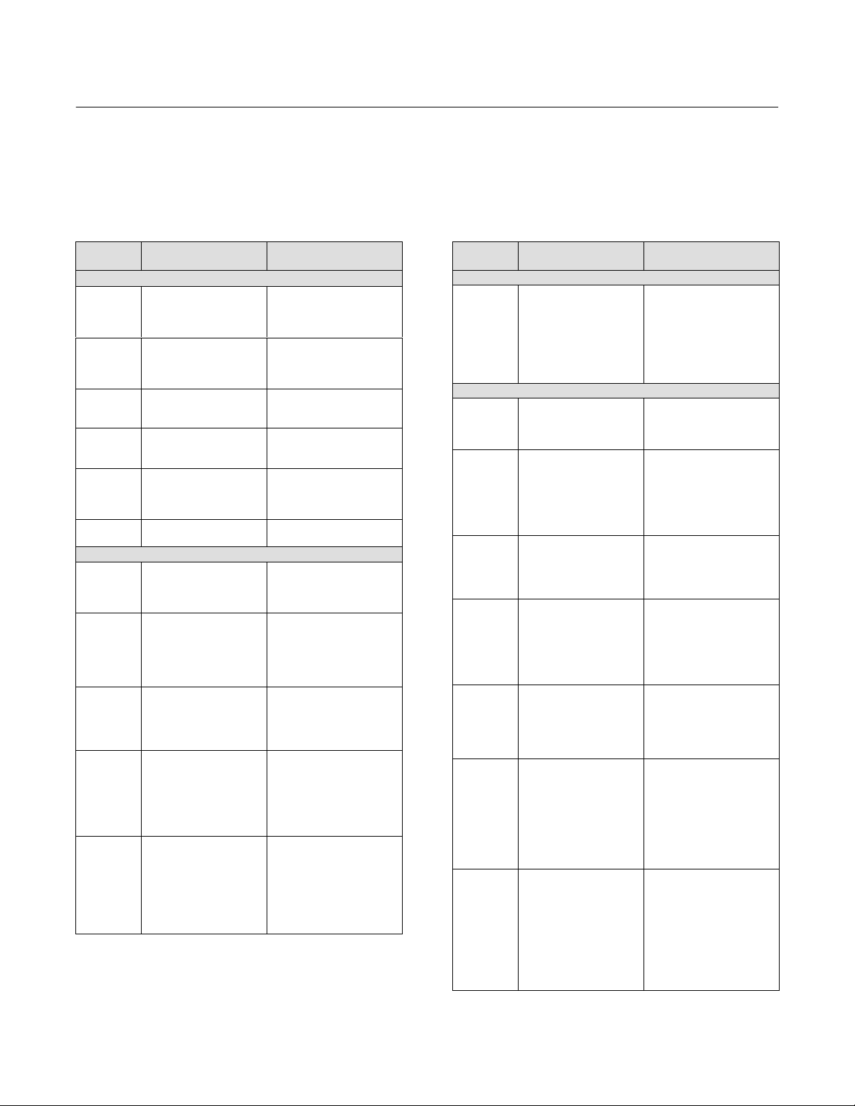
Table 4‐1. Parameters Affected by Restart with
Defaults
Index
Number
1
2
3
4
5 MODE_BLK
14
18
20
26
27
28
32
33
34
37
38
39
1
2
3
4
5
8
9
11 PV_SCALE
12
14
15
17
18
19
20
21
22
Parameter Name Initial Value
Resource Block
ST_REV
TAG_DESC
STRATEGY
ALERT_KEY
TARGET
PERMITTED
NORMAL
GRANT_DENY
FEATURE_SEL
CYCLE_SEL
SHED_RCAS
SHED_ROUT
FAULT_STATE
LIM_NOTIFY
CONFIRM_TIME
WRITE_LOCK
ALARM_SUM_DISABLED
ACK_OPTION
WRITE_PRI
AO Block
ST_REV
TAG_DESC
STRATEGY
ALERT_KEY
MODE_BLK
TARGET
PERMITTED
NORMAL
SP
OUT
EU 100%
EU 0%
Engineering Units
Decimal Places
XD_SCALE
EU 100%
EU 0%
Engineering Units
Decimal Places
IO_OPTS
STATUS_OPTS
CAS_IN
SP_RATE_DN
SP_RATE_UP
SP_HI_LIM
SP_LO_LIM
CHANNEL
-Continued-
0
spaces
0
0
OOS
AUTO or OOS
AUTO
All bits: 0
Set by mfgr.
0:0
640000
640000
1: Clear
MAX_NOTIFY
640000
1: Unlocked
All bits: 0
Disabled
0
0
spaces
0
0
OOS
OOS+MAN+AUTO+CAS+RCAS
CAS+Auto
Dynamic
Dynamic
100
0
%
0
100
0
%
0
All off
All off
BAD
Not Connected
Not Limited
+INF
+INF
100
0
Setpoint
Table 4‐1. Parameters Affected by Restart with
Defaults
Index
Number
23
24
26
27
1
2
3
4
5
8
9
10 PV_SCALE
11
13
14
15
16
17
18
19
20
21
22
23
24
25
26
27
Parameter Name Initial Value
AO Block (continued)
FSTATE_TIME
FSTATE_VAL
RCAS_IN
Status
Value
SHED_OPT
PID Block Parameters
ST_REV
TAG_DESC
STRATEGY
ALERT_KEY
MODE_BLK
TARGET
PERMITTED
NORMAL
SP
OUT
EU 100%
EU 0%
Engineering Units
Decimal Places
OUT_SCALE
EU 100%
EU 0%
Engineering Units
Decimal Places
CONTROL_OPTS
STATUS_OPTS
IN
Status
Value
PV_FTIME
BYPASS
CAS_IN
Status
Value
SP_RATE_DN
SP_RATE_UP
SP_HI_LIM
SP_LO_LIM
GAIN
RESET
BAL_TIME
RATE
BKCAL_IN
Status
Value
-Continued-
0
0
BAD
Not Connected
Not Limited
0 Trk
Uninitialized
0
spaces
0
0
OOS
OOS+MAN+AUTO+CAS+
RCAS+ROUT
AUTO
Dynamic
Dynamic
100
0
%
0
100
0
%
0
0: Bypass enable
All off
BAD
Not Connected
Not Limited
0
0
Uninitialized
BAD
Not Connected
Not Limited
0
+INF
+INF
100
0
1
+INF
0
0
BAD
Not Connected
Not Limited
0
28

Instruction Manual
D103412X012
DVC6200f Digital Valve Controller
Detailed Setup - Resource Block
May 2022
Table 4‐1. Parameters Affected by Restart with
Defaults
Index
Number
28
29
30
32
33
34 SHED_OPTS Uninitialized
38
39
40
41
42
45
46
47
48
49
50
51
52
53
54
55
56
57
58
59
66
69
70
71
72
73
74
Parameter Name Initial Value
PID Block (continued)
OUT_HI_LIM
OUT_LO_LIM
BKCAL_HYS
RCAS_IN
Status
Value
ROUT_IN
Status
Value
TRK_IN_D
Status
Value
TRK_VAL
Status
Value
FF_VAL
Status
Value
FF_SCALE
EU 100%
EU 0%
Engineering Units
Decimal Places
FF_GAIN
ALARM_SUM
DISABLED
ACK_OPTION
ALARM_HYS
HI_HI_PRI
HI_HI_LIM
HI_PRI
HI_LIM
LO_PRI
LO_LIM
LO_LO_PRI
LO_LO_LIM
DV_HI_PRI
DV_HI_LIM
DV_LO_PRI
DV_LO_LIM
BIAS
SP_FTIME
MATHFORM
STRUCTURECONFIG
GAMMA
BETA
IDEABAND
-Continued-
100
0
0.5%
BAD
Not Connected
Not Limited
0 Trk
BAD
Not Connected
Not Limited
0 Trk
BAD
Not Connected
Not Limited
0
BAD
Not Connected
Not Limited
0
BAD
Not Connected
Not Limited
0
100
0
%
0
0
All Off
All Off
0.5%
0
Infinity
0
Infinity
0
- Infinity
0
- Infinity
0
+INF
0
-INF
0
Standard
Err on PI_D
1
0
Table 4‐1. Parameters Affected by Restart with
Defaults
Index
Number
1
2
3
4
5 MODE_BLK
8 OUT_RANGE
10
11
12
13
14
15
16
17
18
19
20
22
Parameter Name Initial Value
ISEL Block
ST_REV
TAG_DESC
STRATEGY
ALERT_KEY
TARGET
PERMITTED
NORMAL
EU_100
EU_0
UNITS_INDEX
DECIMAL
STATUS_OPTS
IN_1
Status
Value
IN_2
Status
Value
IN_3
Status
Value
IN_4
Status
Value
DISABLE_1
Status
Value
DISABLE_2
Status
Value
DISABLE_3
Status
Value
DISABLE_4
Status
Value
SELECT_TYPE
MIN_GOOD
OP_SELECT
Status
Value
-Continued-
0
spaces
0
0
OOS
OOS+MAN+AUTO
AUTO
BAD
100
0
%
0
All off
BAD
Not Connected
Constant
0
BAD
Not Connected
Constant
0
BAD
Not Connected
Constant
0
BAD
Not Connected
Constant
0
BAD
Not Connected
Constant
Use
BAD
Not Connected
Constant
Use
BAD
Not Connected
Constant
Use
BAD
Not Connected
Constant
Use
All off
0
BAD
Not Connected
Constant
0
29

DVC6200f Digital Valve Controller
Detailed Setup - Resource Block
May 2022
Instruction Manual
D103412X012
Table 4‐1. Parameters Affected by Restart with
Defaults
Index
Number
25
26
27
28
29
30
31
32
33
34
35
36
37
38
39
40
41
42
43
44
50
Parameter Name Initial Value
ISEL Block (continued)
IN_5
Status
Value
IN_6
Status
Value
IN_7
Status
Value
IN_8
Status
Value
DISABLE_5
Status
Value
DISABLE_6
Status
Value
DISABLE_7
Status
Value
DISABLE_8
Status
Value
AVG_USE
ALARM_SUM
DISABLED
ACK_OPTION
ALARM_HYS
HI_HI_PRI
HI_HI_LIM
HI_PRI
HI_LIM
LO_PRI
LO_LIM
LO_LO_PRI
LO_LO_LIM
ALM_SEL
-Continued-
BAD
Not Connected
Constant
0
BAD
Not Connected
Constant
0
BAD
Not Connected
Constant
0
BAD
Not Connected
Constant
0
BAD
Not Connected
Constant
Use
BAD
Not Connected
Constant
Use
BAD
Not Connected
Constant
Use
BAD
Not Connected
Constant
Use
8
All off
All off
0.5%
0
Infinity
0
Infinity
0
-Infinity
0
-Infinity
All off
Table 4‐1. Parameters Affected by Restart with
Defaults
Index
Number
1
2
3
4
5
10
11
13
14
15
16
20
21
22
23
1
2
3
4
5
10
11 OUT_2_RANGE
13
14
19 BKCAL_1_IN
20
21
Parameter Name Initial Value
DI Block
ST_REV
TAG_DESC
STRATEGY
ALERT_KEY
MODE_BLK
TARGET
PERMITTED
NORMAL
XD_STATE
OUT_STATE
IO_OPTS
STATUS_OPTS
CHANNEL
PV_FTIME
ALARM_SUM
DISABLED
ACK_OPTION
DISC_PRI
DISC_LIM
OS Block
ST_REV
TAG_DESC
STRATEGY
ALERT_KEY
MODE_BLK
TARGET
PERMITTED
NORMAL
OUT_1_RANGE
EU_100
EU_0
UNITS_INDEX
DECIMAL
EU_100
EU_0
UNITS_INDEX
DECIMAL
STATUS_OPTS
CAS_IN
Status
Value
Status
Value
BKCAL_2_IN
Status
Value
BAL_TIME
-Continued-
0
spaces
0
0
OOS
OOS+MAN+AUTO
AUTO
0
0
All off
All off
0
0
All off
All off
0
0
0
spaces
0
0
OOS
OOS+AUTO+CAS
AUTO+CAS
100
0
%
0
100
0
%
0
All Off
Bad
Not Connected
Not Limited
0
Bad
Not Connected
Not Limited
0
Bad
Not Connected
Not Limited
0
0 seconds
30
 Loading...