


Instruction Manual
D103785X012
DVC6000 HW2 Digital Valve Controller
November 2019
Fisher™ FIELDVUE™ DVC6000 HW2 Digital Valve
Controller
This manual applies to
Instrument Level HC, AD, PD, ODV
Device Type 130b
Hardware Revision 2
Firmware Revision 7
Device Revision 13
DD Revision 71
Contents
Section 1 Introduction 3.................
Scope of Manual 3..............................
Conventions Used in this Manual 3................
Description 3..................................
Specifications 4................................
Related Documents 7...........................
Educational Services 8...........................
Section 2 Wiring Practices 9..............
Control System Requirements 9..................
HART Filter 9.................................
Voltage Available 9............................
Compliance Voltage 11........................
Auxiliary Terminal Wiring Length Guidelines 12....
Maximum Cable Capacitance 12.................
Remote Travel Sensor Connections 13.............
Installation in Conjunction with a Rosemountt
333 HART Tri‐Loopt HART‐to‐Analog
Signal Converter 17.........................
Section 3 Configuration 19...............
Guided Setup 19...............................
Manual Setup 19...............................
Mode and Protection 20........................
Instrument Mode 20.......................
Write Protection 20........................
Instrument 20................................
Identification 20...........................
Serial Numbers 21.........................
Units 21..................................
Terminal Box 21...........................
Input Range 21............................
Spec Sheet 22.............................
Edit Instrument Time 22....................
Travel/Pressure Control 23......................
Travel/Pressure Select 23...................
Cutoffs and Limits 23.......................
Pressure Control 24........................
Pressure Fallback 24........................
Control Mode 24..........................
Characterization 25........................
Dynamic Response 27......................
Tuning 28....................................
Travel Tuning 28...........................
Pressure Tuning 31........................
Travel/Pressure Integral Settings 31..........
Valve and Actuator 32..........................
Partial Stroke Test 34..........................
Outputs 40...................................
Output Terminal Configuration 40............
Switch Configuration 40....................
HART Variable Assignments 41..............
Transmitter Output 41.....................
Burst Mode 41............................
Alert Setup 42.................................
Change to HART 5 / HART 7 42....................
www.Fisher.com

DVC6000 HW2 Digital Valve Controller
November 2019
Instruction Manual
D103785X012
Contents (continued)
Section 4 Calibration 43.................
Calibration Overview 43.........................
Travel Calibration 44...........................
Auto Calibration 44........................
Manual Calibration 46......................
Pushbutton Calibration 47..................
Sensor Calibration 48..........................
Pressure Sensors 48........................
Travel Sensor 49...........................
Analog Input Calibration 53.................
Relay Adjustment 54...........................
Double‐Acting Relay 54.....................
Single‐Acting Relays 55.....................
PST Calibration 56.............................
Section 5 Device Information, Alerts,
and Diagnostics 57.....................
Overview 57...................................
Status & Primary Purpose Variables 57............
Device Information 57.........................
Service Tools 58................................
Device Status 58..............................
Alert Record 58...............................
Alert Reporting 58.............................
Deadband Principle of Operation 61..............
Diagnostics 63................................
Stroke Valve 63............................
Partial Stroke Test 63.......................
Variables 65...................................
Section 6 Maintenance and
Troubleshooting 67.....................
Module Base Maintenance 68.....................
Tools Required 68.............................
Removing the Module Base 68..................
Replacing the Module Base 70...................
Submodule Maintenance 71......................
I/P Converter 71...............................
Printed Wiring Board (PWB) Assembly 73..........
Pneumatic Relay 75............................
Gauges, Pipe Plugs or Tire Valves 76..............
Terminal Box 76................................
Removing the Terminal Box 76..................
Replacing the Terminal Box 77...................
Travel Sensor 77................................
Disassembly 78...............................
DVC6015 Remote Feedback Unit 78..........
DVC6025 Remote Feedback Unit 79..........
DVC6035 Remote Feedback Unit 79..........
Assembly 79..................................
DVC6015 Feedback Unit 79.................
DVC6025 Feedback Unit 80.................
DVC6035 Feedback Unit 82.................
Troubleshooting 84.............................
Checking Voltage Available 84....................
DVC6000 HW2 Technical Support Checklist 87......
Section 7 Parts 89......................
Parts Ordering 89...............................
Parts Kits 89...................................
Parts List 90...................................
DVC6005 Base Unit 90.........................
Pressure Gauges, Pipe Plugs, or Tire
Valve Assemblies 92.........................
Remote Travel Sensor Parts 90..................
HART Filters 92...............................
Appendix A Principle of Operation 99......
HART Communication 99........................
DVC6200 Digital Valve Controller 99...............
Appendix B Device Communicator
Menu Tree 102.......................
Glossary 112...........................
Index 118.............................
2

Instruction Manual
D103785X012
Introduction
November 2019
Section 1 Introduction
Installation, Pneumatic and Electrical Connections, and Initial
Configuration
Refer to the DVC6005 Series Remote Mount quick start guide (D103784X012) for DVC6000 HW2 installation,
connection and initial configuration information. If a copy of this quick start guide is needed contact your Emerson
sales office or visit our website at Fisher.com.
Scope of Manual
This instruction manual is a supplement to the DVC6005 Series Remote Mount quick start guide (D103784X012) that
ships with every instrument. This instruction manual includes product specifications, reference materials, custom
setup information, maintenance procedures, and replacement part details.
This instruction manual describes using the AMS Trex
You can also use Fisher ValveLink
and instrument. For information on using ValveLink software with the instrument refer to ValveLink software help or
documentation.
Do not install, operate, or maintain a DVC6000 HW2 digital valve controller without being fully trained and qualified in
valve, actuator, and accessory installation, operation, and maintenance. To avoid personal injury or property damage,
it is important to carefully read, understand, and follow all of the contents of this manual, including all safety cautions
and warnings. If you have any questions about these instructions, contact your Emerson sales office before
proceeding.
™
software or ValveLink Mobile software to setup, calibrate, and diagnose the valve
™
Device Communicator to set up and calibrate the instrument.
Conventions Used in this Manual
Navigation paths and fast‐key sequences are included for procedures and parameters that can be accessed using the
Device Communicator.
For example, to access Device Setup:
Device Communicator Configure > Guided Setup > Device Setup (2‐1‐1)
Refer to Appendix B for Device Communicator menu trees.
Description
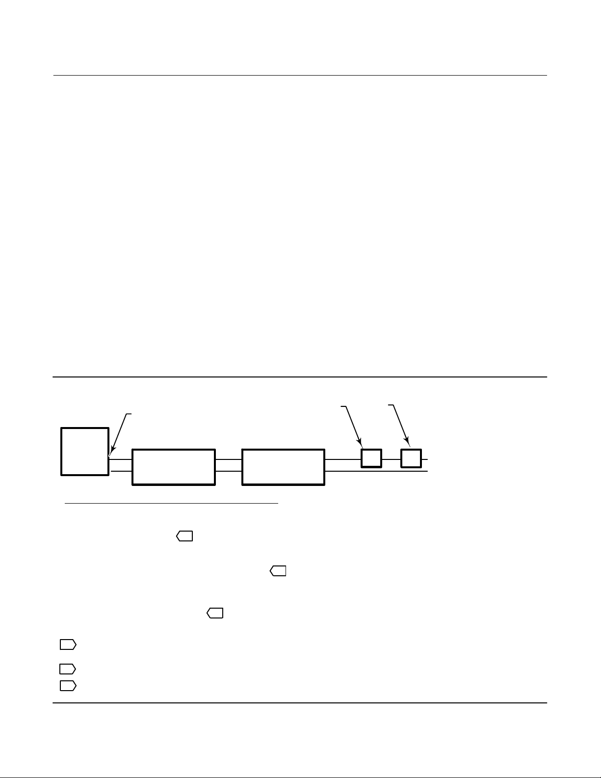
DVC6000 HW2 digital valve controllers (figures 1‐1) are communicating, microprocessor‐based current‐to‐pneumatic
instruments. In addition to the normal function of converting an input current signal to a pneumatic output pressure,
the DVC6000 HW2 digital valve controller, using the HARTr communications protocol, gives easy access to
information critical to process operation. You can gain information from the principal component of the process, the
control valve itself, using the Device Communicator at the valve, or at a field junction box, or by using a personal
computer or operator's console within the control room.
3

Introduction
(2)
(3)
(1)
November 2019
Instruction Manual
D103785X012
Using a personal computer and ValveLink software or
AMS Suite: Intelligent Device Manager, or a Device
Communicator, you can perform several operations with
Figure 1‐1. DVC6000 HW2 Digital Valve Controller
Mounted on Rotary Control Valve/Actuator
the DVC6000 HW2 digital valve controller. You can
obtain general information concerning software revision
level, messages, tag, descriptor, and date.
Diagnostic information is available to aid you when
troubleshooting. Input and output configuration
parameters can be set, and the digital valve controller can
be calibrated. Refer to table 1‐1 for details on the
capabilities of each diagnostic tier.
Using the HART protocol, information from the field can
be integrated into control systems or be received on a
single loop basis.
The DVC6000 HW2 digital valve controller is designed to
directly replace standard pneumatic and
electro‐pneumatic valve mounted positioners.
W8373
Table 1‐1. Instrument Level Capabilities
CAPABILITY
Auto Calibration X X X X
Custom Characterization X X X X
Burst Communication X X X X
Alerts X X X X
Step Response, Drive Signal Test & Dynamic Error Band X X X
Advanced Diagnostics (Valve Signature) X X X
Performance Tuner
Travel Control ‐ Pressure Fallback X X X
Supply Pressure Sensor X X X
Performance Diagnostics X X
Solenoid Valve Testing X X
Lead/Lag Set Point Filter
1. Refer to brochure part # D351146X012 for information on Fisher optimized digital valves for compressor antisurge applications.
2. HC = HART Communicating ; AD = Advanced Diagnostics ; PD = Performance Diagnostics ; ODV = Optimized Digital Valve.
3. Performance Tuner is only available in ValveLink software.
HC AD PD ODV
DIAGNOSTIC LEVEL
X X X
X
Specifications
WARNING
Refer to table 1‐2 for specifications. Incorrect configuration of a positioning instrument could result in the malfunction of
the product, property damage or personal injury.
Specifications for DVC6000 HW2 digital valve controllers are shown in table 1‐2. Specifications for the Device
Communicator can be found in the Device Communicator quick start guide
4
.

Instruction Manual
D103785X012
Table 1‐2. Specifications
Introduction
November 2019
Available Mounting
DVC6000 HW2 digital valve controllers can be
mounted on Fisher and other manufacturers rotary
and sliding‐stem actuators
(1)
DVC6005 HW2: Base unit for 2 inch pipestand or wall
mounting
J DVC6015: Remotely mounted feedback unit for
sliding‐stem applications
J DVC6025: Remotely mounted feedback unit for
rotary or long‐stroke sliding‐stem applications or
J DVC6035: Remotely mounted feedback unit for
quarter‐turn rotary applications
Mounting kit required for mounting feedback unit on
actuator
Mounting the instrument vertically, with the vent at
the bottom of the assembly, or horizontally, with the
vent pointing down, is recommended to allow
drainage of moisture that may be introduced via the
instrument air supply.
Communication Protocol
J HART 5 or J HART 7
Input Signal
Point-to-Point
Analog Input Signal: 4-20 mA DC, nominal; split
ranging available
Minimum Voltage Available at Instrument Terminals
must be 9.5 VDC for analog control, 10 VDC for HART
communication
Minimum Control Current: 4.0 mA
Minimum Current w/o Microprocessor Restart: 3.5 mA
Maximum Voltage: 30 VDC
Overcurrent protected
Reverse Polarity protected
Multi-drop
Instrument Power: 11 to 30 VDC at 10 mA
Reverse Polarity protected
Supply Pressure
(2)
Minimum Recommended: 0.3 bar (5 psig) higher
than maximum actuator requirements
Maximum: 10.0 bar (145 psig) or maximum pressure
rating of the actuator, whichever is lower
Medium: Air or Natural Gas
Supply medium must be clean, dry and non-corrosive
-continued-
Per ISA Standard 7.0.01: A maximum 40 micrometer
particle size in the air system is acceptable. Further
filtration down to 5 micrometer particle size is
recommended. Lubricant content is not to exceed 1
ppm weight (w/w) or volume (v/v) basis.
Condensation in the air supply should be minimized.
Per ISO 8573-1:
Maximum particle density size: Class 7
Oil content: Class 3
Pressure Dew Point: Class 3 or at least 10_C less than
the lowest ambient temperature expected
Output Signal
Pneumatic signal as required by the actuator, up to
full supply pressure.
Minimum Span: 0.4 bar (6 psig)
Maximum Span: 9.5 bar (140 psig)
Action:
Steady‐State Air Consumption
J Double, J Single Direct or J Reverse
(3)(4)
Standard Relay
At 1.4 bar (20 psig) supply pressure:
Less than 0.38 normal m
At 5.5 bar (80 psig) supply pressure:
Less than 1.3 normal m
3
/hr (14 scfh)
3
/hr (49 scfh)
Low Bleed Relay
At 1.4 bar (20 psig) supply pressure:
Average value 0.056 normal m
At 5.5 bar (80 psig) supply pressure:
Average value 0.184 normal m
Maximum Output Capacity
At 1.4 bar (20 psig) supply pressure:
10.0 normal m
3
/hr (375 scfh)
3
/hr (2.1 scfh)
3
/hr (6.9 scfh)
(3)(4)
At 5.5 bar (80 psig) supply pressure:
29.5 normal m
Operating Ambient Temperature Limits
3
/hr (1100 scfh)
(2)(5)
-40 to 85_C (-40 to 185_F) for base unit
-52 to 85_C (-62 to 185_F) for base unit utilizing the
Extreme Temperature option (fluorosilicone
elastomers)
-52 to 125_C (-62 to 257_F) for remote‐mount
feedback unit
Independent Linearity
(6)
Typical Value: ±0.50% of output span
5

Introduction
November 2019
Table 1‐2. Specifications (continued)
Instruction Manual
D103785X012
Electromagnetic Compatibility
Meets EN 61326-1:2013
Immunity—Industrial locations per Table 2 of
the EN 61326-1 standard. Performance is
shown in table 1‐3 below.
Emissions—Class A
ISM equipment rating: Group 1, Class A
Lightning and Surge Protection—The degree of
immunity to lightning is specified as Surge immunity
in table 1‐3. For additional surge protection
commercially available transient protection devices
can be used.
Vibration Testing Method
Tested per ANSI/ISA-S75.13.01 Section 5.3.5. A
resonant frequency search is performed on all three
axes. The instrument is subjected to the ISA specified
1/2 hour endurance test at each major resonance.
Input Impedance
An equivalent impedance of 500 ohms may be used.
This value corresponds to 10V @ 20 mA.
Humidity Testing Method
Tested per IEC 61514‐2
Electrical Classification
Hazardous Area Approvals
CSA— Intrinsically Safe, Explosion‐proof,
Division 2, Dust Ignition-proof
FM— Intrinsically Safe, Explosion‐proof,
Dust Ignition-proof, Non-Incendive
ATEX— Intrinsically Safe, Flameproof, Type n
Dust by intrinsic safety
IECEx— Intrinsically Safe, Flameproof, Type n
Dust by intrinsic safety and enclosure
Electrical Housing
CSA— Type 4X, IP66
FM— Type 4X, IP66
ATEX— IP66
IECEx— IP66
-continued-
Other Classifications/Certifications
Lloyds Register—Marine Type Approval
CUTR—Customs Union Technical Regulations
(Russia, Kazakhstan, Belarus, and Armenia)
INMETRO— National Institute of Metrology, Quality,
and Technology (Brazil)
PESO CCOE— Petroleum and Explosives Safety
Organisation - Chief Controller of Explosives (India)
Contact your Emerson sales office
for
classification/certification specific information.
Connections
Supply Pressure: 1/4 NPT internal and integral pad for
mounting 67CFR regulator
Output Pressure: 1/4 NPT internal
Tubing: 3/8‐inch recommended
Vent: 3/8 NPT internal
Electrical: 1/2 NPT internal or M20
(8)
Actuator Compatibility
Stem Travel (Sliding‐Stem Linear)
Linear Actuators with rated travel between 6.35 mm
(0.25 inch) and 606 mm (23.375 inches)
Shaft Rotation (Quarter‐Turn Rotary)
Rotary Actuators with rated travel between 50
degrees and 180 degrees
Mounting
Weight
DVC6005 HW2 Base Unit: 4.1 kg (9 lbs)
DVC6015 Remote Feedback Unit: 1.3 kg (2.9 lbs)
DVC6025 Remote Feedback Unit: 1.4 kg (3.1 lbs)
DVC6035 Remote Feedback Unit: 0.9 kg (2.0 lbs)
Construction Materials
Housing, module base and terminal box:
A03600 low copper aluminum alloy
Cover: Thermoplastic polyester
Elastomers: Nitrile (standard)
Fluorosilicone (extreme temperature)
6

Instruction Manual
(1)
(2)
(2)
D103785X012
Table 1‐2. Specifications (continued)
Introduction
November 2019
Options
J Supply and output pressure gauges or
J Tire valves J Integral mounted filter regulator
J Low‐Bleed Relay
J Integral 4‐20 mA Position Transmitter
(7)
J Extreme Temperature
(9)
:
On State: up to 1 A
Supply Voltage: 30 VDC maximum
Reference Accuracy: 2% of travel span
Contact your Emerson sales office
or go to Fisher.com
for additional information
4‐20 mA output, isolated
Supply Voltage: 8‐30 VDC
Reference Accuracy: 1% of travel span
The position transmitter meets the requirements of
NAMUR NE43; selectable to show failure high
( > 22.5 mA) or failure low (< 3.6 mA). Fail high only
when the positioner is powered.
J Integral Switch
(9)
:
One isolated switch, configurable throughout the
calibrated travel range or actuated from a device alert
Off State: 0 mA (nominal)
NOTE: Specialized instrument terms are defined in ANSI/ISA Standard 51.1 - Process Instrument Terminology.
1. 4‐conductor shielded cable, 18 to 22 AWG minimum wire size, in rigid or flexible metal conduit, is required for connection between base unit and feedback unit. Pneumatic tubing between base
unit output connection and actuator has been tested to 91 meters (300 feet). At 15 meters (50 feet) there was no performance degradation. At 91 meters there was minimal pneumatic lag.
2. The pressure/temperature limits in this document and any other applicable code or standard should not be exceeded.
3. Normal m
4. Values at 1.4 bar (20 psig) based on a single-acting direct relay; values at 5.5 bar (80 psig) based on double-acting relay.
5. Temperature limits vary based on hazardous area approval.
6. Not applicable for travels less than 19 mm (0.75 inch) or for shaft rotation less than 60 degrees. Also not applicable for digital valve controllers in long‐stroke applications.
7. The Quad O steady-state consumption requirement of 6 scfh can be met by a DVC6000 with low bleed relay option, when used with up to 3.7 bar (53 psi) supply of Natural Gas at 16_C (60_F).
8. M20 electrical connection only available with ATEX approvals
9. The electronic output is available with either the position transmitter or the switch.
3
/hour - Normal cubic meters per hour at 0_C and 1.01325 bar, absolute. Scfh - Standard cubic feet per hour at 60_F and 14.7 psia.
Declaration of SEP
Fisher Controls International LLC declares this
product to be in compliance with Article 4 paragraph
3 of the PED Directive 2014/68/EU. It was designed
and manufactured in accordance with Sound
Engineering Practice (SEP) and cannot bear the CE
marking related to PED compliance.
However, the product may bear the CE marking to
indicate compliance with other applicable European
Community Directives.
Table 1‐3. EMC Summary Results—Immunity
Performance Criteria
Port Phenomenon Basic Standard Test Level
Electrostatic discharge (ESD) IEC 61000‐4‐2
Enclosure
I/O signal/control
Performance criteria: +/- 1% effect.
1. A = No degradation during testing. B = Temporary degradation during testing, but is self‐recovering.
2. Excluding auxiliary switch function, which meets Performance Criteria B.
Radiated EM field IEC 61000‐4‐3
Rated power frequency
magnetic field
Burst IEC 61000‐4‐4 1 kV A A
Surge IEC 61000‐4‐5 1 kV B B
Conducted RF IEC 61000‐4‐6 150 kHz to 80 MHz at 3 Vrms A A
IEC 61000‐4‐8 30 A/m at 50/60Hz A
4 kV contact
8 kV air
80 to 1000 MHz @ 10V/m with 1 kHz AM at 80%
1400 to 2000 MHz @ 3V/m with 1 kHz AM at 80%
2000 to 2700 MHz @ 1V/m with 1 kHz AM at 80%
Point-to-
Point Mode
A
A A
Multi-drop
Mode
A
A
Related Documents
This section lists other documents containing information related to the DVC6000 HW2 digital valve controller. These
documents include:
D Bulletin 62.1:DVC6000 HW2—Fisher FIELDVUE DVC6000 HW2 Digital Valve Controller (D103786X012
D Bulletin 62.1:DVC6005—Fisher FIELDVUE DVC6005 Series Digital Valve Controller and DVC6015, DVC6025, and
DVC6035 Feedback Unit Dimension (D103308X012
)
)
7

Introduction
November 2019
D DVC6005 Series Remote Mount Digital Valve Controller Quick Start Guide (D103784X012)
Instruction Manual
D103785X012
D CSA Hazardous Area Approvals—DVC6005 Series Remote Mount Digital Valve Controllers (D104209X012
D FM Hazardous Area Approvals—DVC6005 Series Remote Mount Digital Valve Controllers (D104210X012
D ATEX Hazardous Area Approvals—DVC6005 Series Remote Mount Digital Valve Controllers (D104211X012
D IECEx Hazardous Area Approvals—DVC6005 Series Remote Mount Digital Valve Controllers (D104212X012)
D FIELDVUE Digital Valve Controller Split Ranging (D103262X012
D Using FIELDVUE Instruments with the Smart HART Loop Interface and Monitor (HIM) (D103263X012
D Using FIELDVUE Instruments with the Smart Wireless THUM Adapter and a HART Interface Module (HIM)
(D103469X012
D Audio Monitor for HART Communications (D103265X012
D HART Field Device Specification - Fisher FIELDVUE DVC6000 HW2 Digital Valve Controller (D103782X012)
D Using the HART Tri‐Loop HART‐to‐Analog Signal Converter with FIELDVUE Digital Valve Controllers (D103267X012
D Implementation of Lock‐in‐Last Strategy (D103261X012
D Fisher HF340 Filter Instruction Manual (D102796X012)
D AMS Trex Device Communicator User Guide
)
)
)
)
)
)
)
)
)
D ValveLink Software Help or Documentation
All documents are available from your Emerson sales office or at Fisher.com.
Educational Services
For information on available courses for the DVC6000 HW2 digital valve controller, as well as a variety of other
products, contact:
Emerson Automation Solutions
Educational Services - Registration
Phone: + 1-641‐754‐3771 or +1-800‐338‐8158
Email: education@emerson.com
emerson.com/fishervalvetraining
8

Instruction Manual
D103785X012
Wiring Practices
November 2019
Section 2 Wiring Practices22
Control System Requirements
There are several parameters that should be checked to ensure the control system is compatible with the
DVC6000 HW2 digital valve controller.
HART Filter
Depending on the control system you are using, a HART filter may be needed to allow HART communication. The
HART filter is a passive device that is inserted in field wiring from the HART loop. The filter is normally installed near the
field wiring terminals of the control system I/O (see figure 2‐1). Its purpose is to effectively isolate the control system
output from modulated HART communication signals and raise the impedance of the control system to allow HART
communication. For more information on the description and use of the HART filter, refer to the appropriate HART
filter instruction manual.
To determine if your system requires a filter contact your Emerson sales office
Note
A HART filter is typically NOT required for any of the Emerson control systems, including PROVOXt, RS3t, and DeltaVt systems.
.
Figure 2‐1. HART Filter Application
NON‐HART BASED DCS
I/O I/O
HART
FILTER
4‐20 mA + HART
DIGITAL VALVE
CONTROLLER
Tx Tx
VALVE
A6188‐1
Voltage Available
The voltage available at the DVC6000 HW2 digital valve controller must be at least 10 VDC. The voltage available at
the instrument is not the actual voltage measured at the instrument when the instrument is connected. The voltage
measured at the instrument is limited by the instrument and is typically less than the voltage available.
9
Wiring Practices
November 2019
Instruction Manual
D103785X012
As shown in figure 2‐2, the voltage available at the instrument depends upon:
D the control system compliance voltage
D if a filter, wireless THUM adapter, or intrinsic safety barrier is used, and
D the wire type and length.
The control system compliance voltage is the maximum voltage at the control system output terminals at which the
control system can produce maximum loop current.
The voltage available at the instrument may be calculated from the following equation:
Voltage Available = [Control System Compliance Voltage (at maximum current)] - [filter voltage drop (if a HART filter is
used)] - [total cable resistance maximum current] - [barrier resistance x maximum current].
The calculated voltage available should be greater than or equal to 10 volts DC.
Table 2‐1 lists the resistance of some typical cables.
The following example shows how to calculate the voltage available for a Honeywellt TDC2000 control system with a
HF340 HART filter, and 1000 feet of Beldent 9501 cable:
Voltage available = [18.5 volts (at 21.05 mA)] - [2.3 volts] - [48 ohms 0.02105 amps]
Voltage available = [18.5] - [2.3] - [1.01]
Voltage available = 15.19 volts
Figure 2‐2. Determining Voltage Available at the Instrument
TOTAL LOOP
COMPLIANCE VOLTAGE
CONTROL
SYSTEM
+
-
Calculate Voltage Available at the Instrument as follows:
Control system compliance voltage
– Filter voltage drop (if used) 1
– Intrinsic safety barrier resistance (if used) x maximum loop current – 2.55 volts (121 ohms x 0.02105 amps)
– Smart Wireless THUM adapter voltage drop (if used) 2
– Total loop cable resistance x maximum loop current – 1.01 volts (48 ohms x 0.02105 amps for
= Voltage available at the instrument 3
NOTES:
1Obtain filter voltage drop. The measured drop will be different than this value. The measured filter voltage drop
depends upon control system output voltage, the intrinsic safety barrier (if used), and the instrument. See note 3.
2The voltage drop of the THUM adapter is linear from 2.25 volts at 3.5 mA to 1.2 volts at 25 mA.
HART FILTER
(if used)
CABLE RESISTANCE
INTRINSIC SAFETY
BARRIER
(if used)
THUM ADAPTER
(IF USED)
R
Example Calculation
18.5 volts (at 21.05 mA)
– 2.3 volts (for HF300 filter)
1000 feet of Belden 9501 cable)
= 15.19 volts, available—if safety barrier (2.55 volts)
is not used
VOLTAGE
AVAILABLE AT THE
+
INSTRUMENT
-
3The voltage available at the instrument is not the voltage measured at the instrument terminals. Once the
instrument is connected, the instrument limits the measured voltage to approximately 8.0 to 9.5 volts.
10

Instruction Manual
(1)
(1)
(2)
(2)
D103785X012
Wiring Practices
Table 2‐1. Cable Characteristics
Cable Type
BS5308/1, 0.5 sq mm 61.0 200 0.022 0.074
BS5308/1, 1.0 sq mm 61.0 200 0.012 0.037
BS5308/1, 1.5 sq mm 61.0 200 0.008 0.025
BS5308/2, 0.5 sq mm 121.9 400 0.022 0.074
BS5308/2, 0.75 sq mm 121.9 400 0.016 0.053
BS5308/2, 1.5 sq mm 121.9 400 0.008 0.025
BELDEN 8303, 22 awg 63.0 206.7 0.030 0.098
BELDEN 8441, 22 awg 83.2 273 0.030 0.098
BELDEN 8767, 22 awg 76.8 252 0.030 0.098
BELDEN 8777, 22 awg 54.9 180 0.030 0.098
BELDEN 9501, 24 awg 50.0 164 0.048 0.157
BELDEN 9680, 24 awg 27.5 90.2 0.048 0.157
BELDEN 9729, 24 awg 22.1 72.5 0.048 0.157
BELDEN 9773, 18 awg 54.9 180 0.012 0.042
BELDEN 9829, 24 awg 27.1 88.9 0.048 0.157
BELDEN 9873, 20 awg 54.9 180 0.020 0.069
1. The capacitance values represent capacitance from one conductor to all other conductors and shield. This is the appropriate value to use in the cable length calculations.
2. The resistance values include both wires of the twisted pair.
Capacitance
pF/Ft
Capacitance
pF/m
Resistance
Ohms/ft
Resistance
Ohms/m
November 2019
Compliance Voltage
If the compliance voltage of the control system is not known, perform the following compliance voltage test.
1. Disconnect the field wiring from the control system and connect equipment as shown in figure 2‐3 to the control
system terminals.
Figure 2‐3. Voltage Test Schematic
kW POTENTIOMETER
1
VOLTMETER
CIRCUIT
UNDER
TEST
A6192‐1
2. Set the control system to provide maximum output current.
3. Increase the resistance of the 1 kW potentiometer, shown in figure 2‐3, until the current observed on the
milliammeter begins to drop quickly.
4. Record the voltage shown on the voltmeter. This is the control system compliance voltage.
MILLIAMMETER
For specific parameter information relating to your control system, contact your Emerson sales office
.
11

Wiring Practices
November 2019
Instruction Manual
D103785X012
Auxiliary Terminal Wiring Length Guidelines
The Auxiliary Input Terminals of a DVC6000 HW2 with instrument level ODV can be used with a locally‐mounted
switch for initiating a partial stroke test. Some applications require that the switch be installed remotely from the
DVC6000 HW2.
The length for wiring connected to the Auxiliary Input Terminals is limited by capacitance. For proper operation of the
Auxiliary Input Terminals capacitance should not exceed 100,000 pF. As with all control signal wiring, good wiring
practices should be observed to minimize adverse effect of electrical noise on the Aux Switch function.
Example Calculation: Capacitance per foot or per meter is required to calculate the length of wire that may be
connected to the Aux switch input. The wire should not exceed the capacitance limit of 100,000 pF. Typically the wire
manufacturer supplies a data sheet which provides all of the electrical properties of the wire. The pertinent parameter
is the highest possible capacitance. If shielded wire is used, the appropriate number is the “Conductor to Other
Conductor & Shield” value.
Example — 18AWG Unshielded Audio, Control and Instrumentation Cable
Manufacturer's specifications include:
Nom. Capacitance Conductor to Conductor @ 1 KHz: 26 pF/ft
Nom. Conductor DC Resistance @ 20 Deg. C: 5.96 Ohms/1000 ft
Max. Operating Voltage - UL 200 V RMS (PLTC, CMG),150 V RMS (ITC)
Allowable Length with this cable = 100,000pF /(26pF/ft) = 3846 ft
Example — 18AWG Shielded Audio, Control and Instrumentation Cable
Manufacturer's specifications include:
Nom. Characteristic Impedance: 29 Ohms
Nom. Inductance: .15 μH/ft
Nom. Capacitance Conductor to Conductor @ 1 KHz: 51 pF/ft
Nom. Cap. Cond. to other Cond. & Shield @ 1 Khz: 97 pF/ft
Allowable Length with this cable = 100,000pF /(97pF/ft) = 1030 ft
The AUX switch input passes less than 1 mA through the switch contacts, and uses less than 5 V, therefore, neither the
resistance nor the voltage rating of the cable are critical. Ensure that switch contact corrosion is prevented. It is
generally advisable that the switch have gold‐plated or sealed contacts.
Maximum Cable Capacitance
The maximum cable length for HART communication is limited by the characteristic capacitance of the cable.
Maximum length due to capacitance can be calculated using the following formulas:
Length(ft) = [160,000 - Cmaster(pF)] [Ccable(pF/ft)]
Length(m) = [160,000 - Cmaster(pF)] [Ccable(pF/m)]
where:
160,000 = a constant derived for FIELDVUE instruments to ensure that the HART network RC time constant will be no
greater than 65 μs (per the HART specification).
Cmaster = the capacitance of the control system or HART filter
12

Instruction Manual
D103785X012
Wiring Practices
November 2019
Ccable = the capacitance of the cable used (see table 2‐1)
t
The following example shows how to calculate the cable length for a Foxboro
I/A control system (1988) with a C
master
of 50, 000 pF and a Belden 9501 cable with characteristic capacitance of 50pF/ft.
Length(ft) = [160,000 - 50,000pF] [50pF/ft]
Length = 2200 ft.
The HART communication cable length is limited by the cable characteristic capacitance. To increase cable length,
select a wire with lower capacitance per foot. Contact your Emerson sales office
for specific information relating to
your control system.
Remote Travel Sensor Connections
The DVC6005 HW2 base unit is designed to receive travel information via a remote sensor. The remote can be any of
the following:
D Emerson Automation Solutions supplied DVC6015, DVC6025 or DVC6035 remote feedback unit; refer to the
DVC6005 Series Remote Mount Digital Valve Controller quick start guide (D103784X012
product,
) that ships with the
D An under‐traveled 10 kOhm potentiometer used in conjunction with onboard 30 kOhm resistor, or
D A potentiometer used in conjunction with two fixed resistors (potentiometer travel is the same as actuator travel).
WARNING
Personal injury or property damage, caused by wiring failure, can result if the feedback wiring connecting the base unit
with the remote feedback unit shares a conduit with any other power or signal wiring.
Do not place feedback wiring in the same conduit as other power or signal wiring.
Note
3‐conductor shielded cable, 22 AWG minimum wire size, is required for connection between base unit and feedback unit.
Pneumatic tubing between base unit output connection and actuator has been tested to 91 meters (300 feet). At 15 meters (50
feet) there was no performance degradation. At 91 meters there was minimal pneumatic lag.
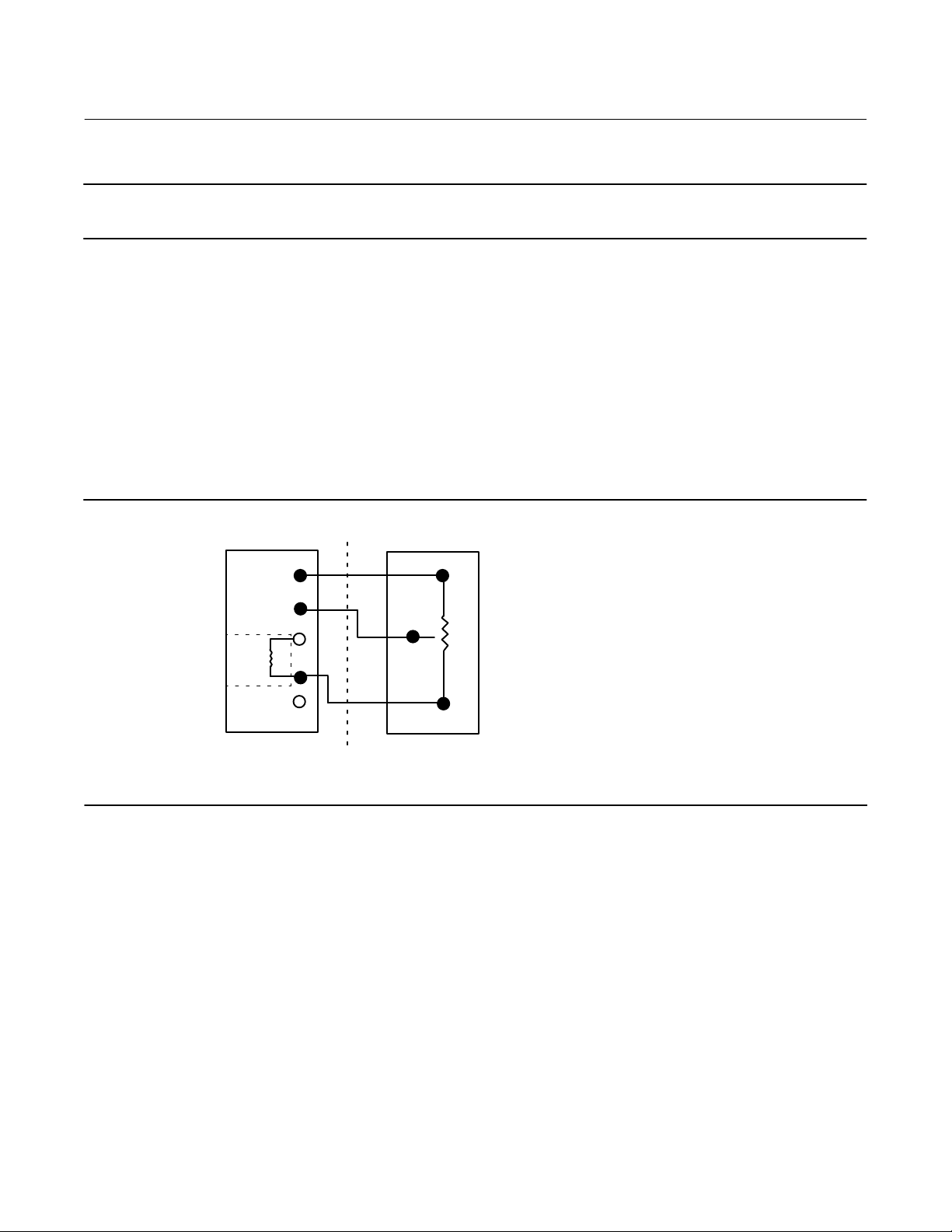
Using an External 10 kOhm External Potentiometer as a Remote Travel Sensor
Note
Potentiometer travel must be between 1.3 and 1.6 times greater than the actuator travel. For example: if an actuator has a travel
of 9 inches, then a linear potentiometer must be selected with a rated travel between 11.7 and 14.4 inches. The resistive element
must be tapered from 0 kOhm to 10 kOhm over rated travel of the potentiometer. The actuator will only use 63 to 76 % of the
potentiometer rated travel.
13
Wiring Practices
November 2019
Note
The digital valve controller must be configured using the SStem/Roller selection on the menu of the appropriate setup device.
Instruction Manual
D103785X012
The DVC6005 HW2 base unit was designed to work with a 40 kOhm potentiometer for travel feedback. However,
there are linear potentiometers that are readily available with a rated resistance of 10 kOhm. Therefore, the feedback
connections terminal box of the DVC6005 HW2 contains an additional 30 kOhm fixed resistor that may be added to
the circuit. This brings the total resistance up to the required 40 kOhm.
1. Mount the external 10 kOhm potentiometer to the actuator such that the mid‐travel position of the potentiometer
(5 kOhm) corresponds to the mid‐travel position of the actuator. This will leave an equal amount of unused resistive
element on both ends of the travel, which is required by the digital valve controller to function properly.
2. On the base unit, remove the feedback connections terminal box cap.
3. If necessary, install conduit between the potentiometer and the base unit following applicable local and national
electrical codes. Route the 3‐conductor shielded cable between the two units (refer to figure 2‐4).
Figure 2‐4. Terminal Details for Connecting a FIELDVUE DVC6005 HW2 Base Unit and a 10k Ohm External
Potentiometer
3
2
INTERNAL
(30k W)
BASE UNIT TERMINATION BOX
(DVC6005 HW2)
1
30k
3RD PARTY FEEDBACK ELEMENT
(WITH 10k W POTENTIOMETER)
"
10k W
4. Connect one wire of the 3‐conductor shielded cable between the terminal labeled “30kW” on the base unit and one
end lead of the potentiometer.
5. Connect the second wire of the 3‐conductor shielded cable between the middle lead (wiper) of the 10 kOhm
potentiometer to Terminal 2 on the base unit.
6. Connect the third wire of the 3‐conductor shielded cable between Terminal 3 on the base unit and the other
end‐lead of the 10 kOhm potentiometer.
7. Connect the cable shield or drain wire to the ground screw in the feedback connections terminal box of the base
unit. Do not connect the shield or drain wire to the external potentiometer.
8. Replace and tighten the base unit cover.
14

Instruction Manual
D103785X012
Wiring Practices
November 2019
Using a Potentiometer with Two Fixed Resistors as a Remote Travel Sensor
Perform the following procedure if a potentiometer is used with the same, or slightly longer travel than the actuator's
travel.
Note
The potentiometer must be capable of resistance close to 0 Ohms.
CAUTION
To prevent damage to the potentiometer, ensure that it is free to travel the entire length of the actuator's travel.
Note
The digital valve controller must be configured using the SStem/Roller selection on the menu of the appropriate setup device.
This procedure uses three resistors connected in series, two fixed resistors and one potentiometer. Three conditions
must be met for the resistor combination to correctly operate the digital valve controller:
D The maximum resistance of the potentiometer [Rpot(max)] must be between 3.9 kOhm and 10 kOhm.
D The resistance of R
D The resistance of R
is 4.25 times greater than Rpot(max).
1
is 4 times less than Rpot(max).
2
WARNING
To avoid personal injury or property damage from an uncontrolled process ensure that the R1 resistor is properly insulated
before installing it in the terminal box.
1. On the base unit, remove the feedback connections terminal box cap.
2. If necessary, install conduit between the two‐resistor series and the base unit following applicable local and national
electrical codes. Route the 3‐conductor shielded cable between the two units (refer to figure 2‐5).
15

Wiring Practices
November 2019
Instruction Manual
D103785X012
Figure 2‐5. Terminal Details for Connecting a FIELDVUE DVC6005 HW2 Base Unit and a Three‐Resistor Series
3
2
1
30kW
(R1)
BASE UNIT TERMINATION BOX
(DVC6005 HW2)
THREE‐RESISTOR SERIES
(R
)
2
"
(R
)
pot
3. Install the fixed resistor (R1) across the unlabeled bottom Terminal and Terminal #1. The bottom terminal does not
have a screw. The screw on the 30 kOhm terminal can be used. R1 must be properly insulated when installed in the
terminal box to prevent personal injury or property damage.
4. Connect one wire of the 3‐conductor shielded cable between the unlabeled bottom Terminal on the base unit and
an end‐lead of the external potentiometer (R
pot
).
5. Connect the second wire of the 3‐conductor shielded cable between the middle lead (wiper) of the external
potentiometer (R
6. Connect the third wire of the 3‐conductor shielded cable between between a lead on fixed resistor (R
) and Terminal 2 on the base unit.
pot
) and
2
terminal #3 of the base unit.
7. Connect the available end‐lead on the potentiometer (R
) with the available lead on fixed resistor (R2).
pot
8. Connect the cable shield or drain wire to the ground screw in the feedback connections terminal box of the base
unit. Do not connect the shield or drain wire to the two‐resistor series.
9. Replace and tighten the base unit cover.
Example: Using a linear potentiometer rated at 400 Ohms/inch on an actuator with 16” of travel.
16
D R
D R
D R
pot(max)
1
2
is 400 Ohms/in x 16” = 6.4 kOhm
= 6.4 kOhm x 4.25 = 27.2 kOhm
= 6.4 kOhm / 4 = 1.6 kOhm

Instruction Manual
D103785X012
Wiring Practices
November 2019
Installation in Conjunction with a Rosemount 333 HART Tri‐Loop
HART‐to‐Analog Signal Converter
Use the DVC6000 HW2 digital valve controller in operation with a Rosemount 333 HART Tri‐Loop HART‐to‐Analog
Signal Converter to acquire an independent 4‐20 mA analog output signal for the analog input, travel target, pressure,
or travel. The HART Tri‐Loop accepts any three of these digital signals and converts them into three separate 4‐20 mA
analog channels.
Refer to figure 2‐6 for basic installation information. Refer to the Refer to the 333 HART Tri‐Loop HART‐to‐Analog
Signal Converter Product Manual (00809-0100-4754
Figure 2‐6. HART Tri‐Loop Installation Flowchart
START HERE
) for complete installation information.
Unpack the
HART Tri‐Loop
Review the HART
Tri‐Loop Product
Manual
Digital valve
Set the digital
valve controller
Burst Option
Set the digital
valve controller
Burst Mode
E0365
controller
Installed?
Yes
No
Install the digital
valve controller.
Install the HART Tri‐
Loop; See HART Tri‐
Loop product manual
Mount the HART
Tri‐Loop to the
DIN rail
Wire the digital
valve controller to
the HART Tri‐Loop
Install Channel 1
wires from HART
Tri‐Loop to the
control room
(Optional) Install
Channel 2 and 3 wires
from HART Tri‐Loop to
the control room
Configure the HART
Tri‐Loop to receive
digital valve controller
burst commands
Pass system
test?
Yes
DONE
No
Check
troubleshooting
procedures in
HART Tri‐Loop
product manual
17

Wiring Practices
November 2019
Instruction Manual
D103785X012
Commissioning the Digital Valve Controller for use with the HART
Tri‐Loop Signal Converter
To prepare the digital valve controller for use with a 333 HART Tri‐Loop, you must configure the digital valve controller
to burst mode, and select Burst Command 3. In burst mode, the digital valve controller provides digital information to
the HART Tri‐Loop HART‐to‐Analog Signal Converter. The HART Tri‐Loop converts the digital information to a 4 to 20
mA analog signal. Each burst message contains the latest value of the primary (analog input), secondary (travel
target), tertiary (configured output pressure), and quaternary (travel) variables.
To commission a DVC6000 HW2 for use with a HART Tri‐Loop, perform the following procedures.
Enable Burst Operation
With I/O Package
Device Communicator
Select Burst Enable and follow the prompts to enable burst mode. Then select Burst Command and follow the prompts
to configure Loop Current/PV/SV/TV/QV.
Configure > Manual Setup > Outputs > Burst Mode (2‐2‐6‐6) HC, AD, PD or (2-2-7-6) ODV
Without I/O Package
Configure > Manual Setup > Outputs > Burst Mode (2‐2‐6‐2) HC, AD, PD or (2-2-7-2) ODV
Select the HART Variable Assignments
With I/O Package
Device Communicator
Configure the HART Variable Assignments. The Primary Variable (PV) is always Analog Input. The Secondary Variable
(SV), Tertiary Variable (TV) and Quaternary Variable (QV) can be configured to any of the following variables. The
variable assignments in the DVC6000 HW2 must correspond to the variable assignments in the Tri-Loop.
D Setpoint
D Travel (see note below)
D Pressure A
D Pressure B
D Pressure AB
D Supply Pressure
D Drive Signal
D Analog Input
Note
If the instrument is configured to operate in pressure control mode, or detects an invalid travel sensor reading, the Travel variable
will report pressure in percent of bench set range.
Configure > Manual Setup > Outputs > HART Variable Assignments (2-2-6-4) HC, AD, PD or (2-2-7-4) ODV
Without I/O Package
Configure > Manual Setup > Outputs > HART Variable Assignments (2-2-6-1) HC, AD, PD or (2-2-7-1) ODV
18

Instruction Manual
(1)
D103785X012
Configuration
November 2019
Section 3 Configuration
Guided Setup
Device Communicator Configure > Guided Setup (2‐1)
The following procedures will guide you through the instrument setup process.
Device Setup is used to configure actuator and valve information, calibrate the valve assembly, and assign the tuning
set for the valve assembly.
Auto Calibration is used to establish the limits of physical travel. During this process, the valve will fully stroke from
one travel extreme to the other. There are three calibration options to choose from:
d Autocalibrate – Standard runs the full calibration process (recommended).
d Autocalibrate – Without Biases establishes the travel end points, but does not adjust the Minor Loop Feedback
bias. This is for advanced use when manually setting the biases for large actuators.
d Advanced Settings allows additional custom configuration of calibration parameters. This is for advanced use
when calibrating large actuators.
Manual Setup33
Manual Setup allows you to configure the digital valve controller to your application. Table 3‐1 lists the default settings
for a standard factory configuration. You can adjust actuator response, set the various modes, alerts, ranges, travel
cutoffs and limits. You can also restart the instrument and set the protection.
Table 3‐1. Default Detailed Setup Parameters
Setup Parameter Default Setting
Control Mode Analog
Restart Control Mode Resume Last
Analog In Range Low 4 mA
Analog In Range High 20 mA
Instrument
Configuration
Dynamic Response and
Tuning
Analog Input Units mA
Local AutoCal Button Disabled
Polling Address 0
Burst Mode Enable No
Burst Command 3
Cmd 3 (Trending) Pressure A-B
Input Characterization Linear
Travel Limit High 125%
Travel Limit Low -25%
Travel/Pressure Cutoff High 99.46%
Travel/Pressure Cutoff Low 0.50%
Set Point Rate Open 0%/sec
Set Point Rate Close 0%/sec
Set Point Filter Time (Lag Time) 0 sec
Integrator Enable Yes
Integral Gain 9.4 repeats/minute
Integral Deadzone 0.26%
-continued on next page-
19

Configuration
(1)
(2)
November 2019
Instruction Manual
D103785X012
Table 3‐1. Default Detailed Setup Parameters (continued)
Setup Parameter Default Setting
Travel Deviation Alert Enable Yes
Travel Deviation Alert Point 5%
Travel Deviation Time 9.99 sec
Deviation & Other Alerts
1. The settings listed are for standard factory configuration. DVC6000 HW2 instruments can also be ordered with custom configuration
settings. Refer to the order requisition for custom settings (if specified) .
2. Adjust to bar, kPa, or Kg/cm
Pressure Deviation Alert Enable Yes
Pressure Deviation Alert Point 5 psi
Pressure Deviation Alert Time 5.0 sec
Drive Signal Alert Enable Yes
Supply Pressure Alert Enable Yes
2
if necessary
Mode and Protection
Device Communicator Configure > Manual Setup > Mode and Protection (2‐2‐1)
Instrument Mode
There are two instrument modes for the DVC6000 HW2; In Service or Out of Service. In Service is the normal operating
mode such that the instrument follows the 420 mA control signal. Out of Service is required in some cases to modify
configuration parameters or to run diagnostics.
Note
Some changes that require the instrument to be taken Out Of Service will not take effect until the instrument is placed back In
Service or the instrument is restarted.
Write Protection
There are two Write Protection modes for the DVC6000 HW2: Not Protected or Protected. Protected prevents
configuration and calibration changes to the instrument. The default setting is Not Protected. Write Protection can be
changed to Protected remotely. However, to change Write Protection to Not Protected, you must have physical access
to the instrument. The procedure will require you to press a button ( ) on the terminal box as a security measure.
Instrument
Device Communicator Configure > Manual Setup > Instrument (2‐2‐2)
Follow the prompts on the Device Communicator display to configure the following Instrument parameters:
Identification
D HART Tag—A tag name up to 8 characters is available for the instrument. The HART tag is the easiest way to
distinguish between instruments in a multi‐instrument environment. Use the HART tag to label instruments
electronically according to the requirements of your application. The tag you assign is automatically displayed
when the Device Communicator establishes contact with the digital valve controller at power‐up.
D HART Long Tag (HART Universal Revision 7 only)—A tag name up to 32 characters is available for the instrument.
20

Instruction Manual
D103785X012
D Description—Enter a description for the application with up to 16 characters. The description provides a longer
user‐defined electronic label to assist with more specific instrument identification than is available with the HART
tag.
D Message—Enter any message with up to 32 characters. Message provides the most specific user‐defined means for
identifying individual instruments in multi‐instrument environments.
D Polling Address—If the digital valve controller is used in point‐to‐point operation, the Polling Address is 0. When
several devices are connected in the same loop, such as for split ranging, each device must be assigned a unique
polling address. The Polling Address is set to a value between 0 and 63 for HART 7 and 0 and 15 for HART 5. To
change the polling address the instrument must be Out Of Service.
For the Device Communicator to be able to communicate with a device whose polling address is not 0, it must be
configured to automatically search for all or specific connected devices.
Configuration
November 2019
Serial Numbers
D Instrument Serial Number—Enter the serial number on the instrument nameplate, up to 12 characters.
D Valve Serial Number—Enter the serial number for the valve in the application, up to 12 characters.
Units
D Pressure Units—Defines the output and supply pressure units in either psi, bar, kPa, or kg/cm2.
D Temperature Units—Degrees Fahrenheit or Celsius. The temperature measured is from a sensor mounted on the
digital valve controller's printed wiring board.
D Analog Input Units—Permits defining the Analog Input Units in mA or percent of 4-20 mA range.
Terminal Box
D Calibration (CAL) Button—This button is near the wiring terminals in the terminal box and provides a quick means to
autocalibrate the instrument. The button must be pressed for 3 to 10 seconds. Autocalibration will move the valve
through the full range of travel whether the Instrument Mode is In Service or Out of Service. However, if the Write
Protection is Protected, this button will not be active. To abort, press the button again for 1 second. The calibration
button is disabled by default.
D Auxiliary Terminal Action—These wire terminals can be configured to initiate a partial stroke test upon detection of
a short across the (+) and (-) terminals. The terminals must be shorted for 3 to 10 seconds.
Note
Auxiliary Terminal Action is only available for instrument level ODV.
Analog Input Range
D Input Range Hi—Permits setting the Input Range High value. Input Range High should correspond to Travel Range
High, if the Zero Power Condition is configured as closed. If the Zero Power Condition is configured as open, Input
Range High corresponds to Travel Range Low. See figure 3‐1.
21

Configuration
November 2019
Instruction Manual
D103785X012
D Input Range Lo—Permits setting the Input Range Low value. Input Range Low should correspond to Travel Range
Low, if the Zero Power Condition is configured as closed. If the Zero Power Condition is configured as open, Input
Range Low corresponds to Travel Range High. See figure 3‐1.
Figure 3‐1. Calibrated Travel to Analog Input Relationship
TRAVEL
RANGE
HIGH
CALIBRATED TRAVEL, %
TRAVEL
RANGE
LOW
ZPC = OPEN
ZPC = CLOSED
THE SHAPE OF THESE LINES
DEPENDS ON THE INPUT
CHARACTERISTICS LINEAR
CHARACTERISTIC SHOWN
ANALOG INPUT
INPUT RANGE
NOTE:
ZPC = ZERO POWER CONDITION
A6531‐1
LOW
mA OR % OF 4‐20 mA
INPUT RANGE
HIGH
Spec Sheet
The Spec Sheet provides a means to store the entire control valve specifications on board the DVC6000 HW2.
Edit Instrument Time
Permits setting the instrument clock. When alerts are stored in the alert record, the record includes the time and date.
The instrument clock uses a 24‐hour format.
22

Instruction Manual
D103785X012
Configuration
November 2019
Travel/Pressure Control
Device Communicator Configure > Manual Setup > Travel/Pressure Control (2‐2-3)
Travel/Pressure Select
This defines the operating mode of the instrument as well as the behavior of the instrument should the travel sensor
fail. There are four choices:
D Travel Control—The instrument is controlling to a target travel. Fallback is not enabled.
D Pressure Control—The instrument is controlling to a target pressure. Fallback is not enabled.
D Fallback-Sensor Failure—The instrument will fallback to pressure control if a travel sensor failure is detected.
D Fallback-Sensor/Tvl Deviation—The instrument will fallback to pressure control if a travel sensor failure is detected,
or if the Tvl Dev Press Fallback setting is exceeded for more than the Tvl Dev Press Fallback Time.
Note
Travel / Pressure Select must be set to Travel for double‐acting actuators
Cutoffs and Limits
D Hi Limit/Cutoff Select—When the Hi Cutoff/Limit Select is configured for Cutoff, the Travel Target is set to 123%
when the Travel exceeds the Hi Cutoff Point. When the Hi Cutoff/Limit Select is configured for Limit, the Travel
Target will not exceed the Hi Limit Point.
D Hi Limit/Cutoff Point—This is the point within the calibrated travel range above which the Limit or Cutoff is in effect.
When using cutoffs, a Cutoff Hi of 99.5% is recommended to ensure valve goes fully open. The Hi Cutoff/Limit is
deactivated by setting it to 125%.
D Hi Soft Cutoff Rate—This setting allows the valve to ramp to the high travel extreme when the Cutoff Point is
reached at the configured rate. This provides a controlled ramp into the seat in order to minimize seat damage.
When set to 0%/sec, the Soft Cutoff rate is disabled.
D Lo Limit/Cutoff Select—When the Lo Cutoff/Limit Select is configured for Cutoff, the Travel Target is set to 23%
when the Travel is below the Lo Cutoff Point. When the Hi Cutoff/Limit Select is configured for Limit, the Travel
Target will not fall below the Lo Limit Point.
D Lo Limit/Cutoff Point—This is the point within the calibrated travel range below which the Limit or Cutoff is in effect.
When using cutoffs, a Cutoff Lo of 0.5% is recommended to help ensure maximum shutoff seat loading. The Lo
Limit/Cutoff is deactivated by setting it to 25%.
D Lo Soft Cutoff Rate—This setting allows the valve to ramp to the low travel extreme when the Cutoff Point is reached
at the configured rate. This provides a controlled ramp into the seat in order to minimize seat damage. When set to
0%/sec, the Soft Cutoff rate is disabled.
23

Configuration
November 2019
Instruction Manual
D103785X012
Pressure Control
D Pressure Range High—The high end of output pressure range. Enter the pressure that corresponds with 100% valve
travel when Zero Power Condition is closed, or 0% valve travel when Zero Power Condition is open. This pressure
must be greater than the Pressure Range Lo.
D Pressure Range Lo—The low end of the output pressure range. Enter the pressure that corresponds to 0% valve
travel when Zero Power Condition is closed, or 100% valve travel when Zero Power Condition is open. This pressure
must be less than the Pressure Range Hi.
Pressure Fallback
Note
Pressure Fallback is available for instrument level AD, PD, ODV.
D Tvl Dev Press Fallback—When the difference between the travel target and the actual travel exceeds this value for
more than the Tvl Dev Press Fallback Time, the instrument will disregard the travel feedback and control based on
output pressure.
D Tvl Dev Press Fallback Time—The time, in seconds, that the travel target and the actual travel must be exceeded
before the instrument falls back into pressure control.
D Fallback Recovery—If the instrument has fallen into pressure control and the feedback problem is resolved, recovery
to travel control can occur automatically or with manual intervention. To return to travel control when Manual
Recovery is selected, change the Fallback Recovery to Auto Recovery, and then back to Manual Recovery (if
desired).
Control Mode
D Control Mode—Displays the current control mode of the instrument. This will show Analog if the instrument is in
PointtoPoint mode and is using a 420 mA signal for its power and set point. This will show Digital if the
instrument is in Multidrop mode and is using 24 VDC for power and a digital set point for control.
Note
Another mode, Test, may be displayed. Normally the instrument should not be in the Test mode. The digital valve controller
automatically switches to this mode whenever it needs to stroke the valve during calibration or stroke valve, for example.
However, if you abort from a procedure where the instrument is in the test mode, it may remain in this mode. To take the
instrument out of the Test mode, select Change Control Mode and enter Analog or Digital.
D Change Control Mode—Allows you to configure the control mode to Analog or Digital.
D Restart Control Mode—Defines the Control Mode of the instrument after a restart (e.g. power cycle). Available
choices are Resume Last, Analog and Digital.
24

Instruction Manual
D103785X012
Configuration
November 2019
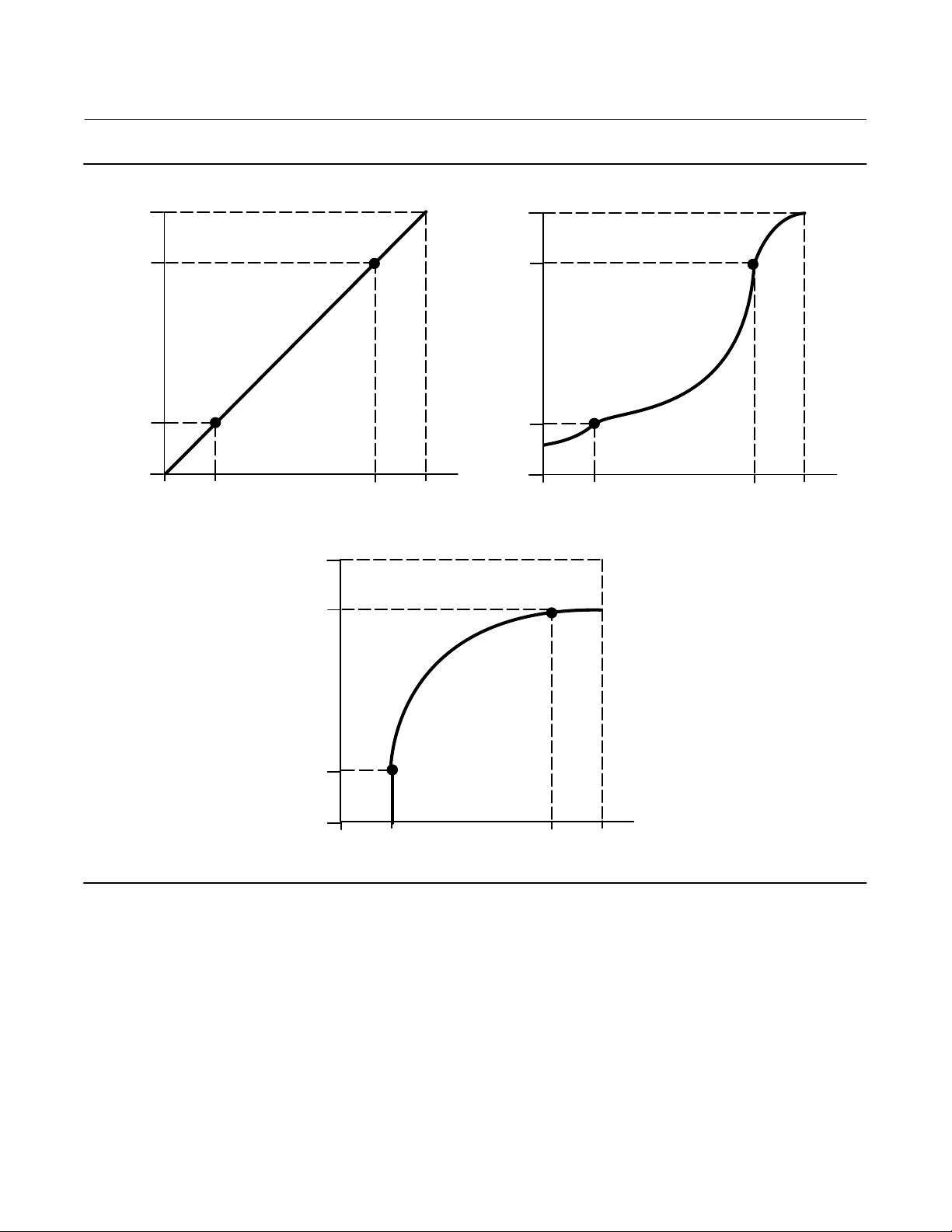
Characterization
D Input Characterization
Input Characterization defines the relationship between the travel target and ranged set point. Ranged set point is the
input to the characterization function. If the zero power condition equals closed, then a set point of 0% corresponds to
a ranged input of 0%. If the zero power condition equals open, a set point of 0% corresponds to a ranged input of 100%.
Travel target is the output from the characterization function.
To select an input characterization, select Input Characterization from the Characterization menu. You can select from
the three fixed input characteristics shown in figure 3‐2 or you can select a custom characteristic. Figure 3‐2 shows the
relationship between the travel target and ranged set point for the fixed input characteristics, assuming the Zero
Power Condition is configured as closed.
You can specify 21 points on a custom characteristic curve. Each point defines a travel target, in % of ranged travel, for
a corresponding set point, in % of ranged set point. Set point values range from -6.25% to 106.25%. Before
modification, the custom characteristic is linear.
D Custom Characterization
To define a custom input character, select Custom Characterization from the Characterization menu. Select the point
you wish to define (1 to 21), then enter the desired set point value. Press Enter then enter the desired travel target for
the corresponding set point. When finished, select point 0 to return to the Characterization menu.
With input characterization you can modify the overall characteristic of the valve and instrument combination.
Selecting an equal percentage, quick opening, or custom (other than the default of linear) input characteristic
modifies the overall valve and instrument characteristic. However, if you select the linear input characteristic, the
overall valve and instrument characteristic is the characteristic of the valve, which is determined by the valve trim
(i.e., the plug or cage).
25
Configuration
November 2019
Instruction Manual
D103785X012
Figure 3‐2. Travel Target Versus Ranged Set Point, for Various Input Characteristics (Zero Power Condition = Closed)
125
100
Travel Target, %
0
-25
-25 0 125100
Ranged Set Point, %
Input Characteristic = Linear
125
100
125
100
Travel Target, %
0
-25
-25 0 125100
Ranged Set Point, %
Input Characteristic = Equal Percentage
26
A6535‐1
Travel Target, %
0
-25
-25 0 125100
Ranged Set Point, %
Input Characteristic = Quick Opening

Instruction Manual
D103785X012
Configuration
November 2019
Dynamic Response
D SP Rate Open—Maximum rate (% of valve travel per second) at which the digital valve controller will move to the
open position regardless of the rate of input current change. A value of 0 will deactivate this feature and allow the
valve to stroke open as fast as possible.
D SP Rate Close—Maximum rate (% of valve travel per second) at which the digital valve controller will move to the
close position regardless of the rate of input current change. A value of 0 will deactivate this feature and allow the
valve to stroke close as fast as possible.
D Set Point Filter Time (Lag Time)—The Set Point Filter Time (Lag Time) slows the response of the digital valve
controller. A value ranging from 0.2 to 10.0 can be used for noisy or fast processes to improve closed loop process
control. Entering a value of 0.0 will deactivate the lag filter.
Note
Set Point Filter Time (Lag Time) is available for instrument level HC, AD, and PD.
D Lead/Lag Set Point Filter—ODV devices have access to a lead‐lag set point filter that can be used to improve a valve's
dynamic response. The lead‐lag filter is part of the set point processing routine that reshapes the input signal before
it becomes travel set point. Lead‐lag filters are characterized by lead and lag time constants.
Note
Lead/Lag is only available for instrument level ODV.
When the valve is in its active control region (off the seat), the lead‐lag filter improves small amplitude response by
momentarily overdriving the travel set point. This is useful when the actuator is large and equipped with accessories.
As a result, any volume boosters that are present will be activated. The longer the lag time, the more pronounced the
overdrive. Since the lead‐lag input filter is used to enhance the dynamic response of a control valve, filter parameters
should be set after the tuning parameters have been established.
When the valve is at its seat, the lead‐lag filter also has a boost function that sets the initial conditions of the filter
artificially low so that small amplitude signal changes appear to be large signal changes to the filter. The boost
function introduces a large spike that momentarily overdrives the instrument and activates any external volume
boosters that may be present. The lead‐lag boost function is normally disabled except for those cases where the valve
must respond to small command signals off the seat. By setting the lead/lag ratio in the opening and closing directions
to 1.0, the boost function can be enabled without introducing lead‐lag dynamics in the active control region. See table
3‐2 for typical lead‐lag filter settings.
Table 3‐2. Typical Lead/Lag Filter Settings for Instrument Level ODV
Parameter Description Typical Value
Lag Time First order time constant. A value of 0.0 will disable the lead‐lag filter. 0.2 sec
Opening Lead/Lag Ratio Initial response to the filter in the opening direction. 2.0
Closing Lead/Lag Ratio Initial response to the filter in the closing direction. 2.0
Lead‐Lag Boost Initial conditions of the lead‐lag filter when the lower travel cutoff is active. Off
27
Configuration
November 2019
Instruction Manual
D103785X012
Tuning
Device Communicator Configure > Manual Setup > Tuning (2‐2-4)
Travel Tuning
WARNING
Changes to the tuning set may cause the valve/actuator assembly to stroke. To avoid personal injury and property damage
caused by moving parts, keep hands, tools, and other objects away from the valve/actuator assembly.
D Travel Tuning Set
There are eleven tuning sets to choose from. Each tuning set provides a preselected value for the digital valve
controller gain settings. Tuning set C provides the slowest response and M provides the fastest response.
Table 3‐3 lists the proportional gain, velocity gain and minor loop feedback gain values for preselected tuning sets.
Table 3‐3. Gain Values for Preselected Travel Tuning Sets
Tuning Set Proportional Gain Velocity Gain Minor Loop Feedback Gain
C
D
E
F
G
H
I
J
K
L
M
X (Expert) User Adjusted User Adjusted User Adjusted
4.4
4.8
5.5
6.2
7.2
8.4
9.7
11.3
13.1
15.5
18.0
3.0
3.0
3.0
3.1
3.6
4.2
4.85
5.65
6.0
6.0
6.0
35
35
35
35
34
31
27
23
18
12
12
In addition, you can specify Expert tuning and individually set the proportional gain, velocity gain, and minor loop
feedback gain. Individually setting or changing any tuning parameter or running Stabilize/Optimize will automatically
change the tuning set to X (expert).
Note
Use Expert tuning only if standard tuning has not achieved the desired results.
Stabilize/Optimize, or Performance Tuner in ValveLink software, may be used to achieve the desired results more rapidly than
manual Expert tuning.
Table 3‐4 provides tuning set selection guidelines for Fisher and Baumann actuators. These tuning sets are only
recommended starting points. After you finish setting up and calibrating the instrument, you may have to select either
a higher or lower tuning set to get the desired response.
28
Instruction Manual
(1)
D103785X012
Table 3‐4. Actuator Information for Initial Setup
Actuator
Manufacturer
Fisher
Baumann
1. X = Expert Tuning. Proportional Gain = 4.2; Velocity Gain = 3.0; Minor Loop Feedback Gain = 18.0
2. Values shown are for Relay A and C. Reverse for Relay B.
Actuator
Model
585C & 585CR
657
667
1051 & 1052
1061
1066SR
2052
3024C
GX
Air to Extend
Air to Retract Counterclockwise
Rotary
Actuator Size Actuator Style
25
50
60
68, 80
100, 130
30
34, 40
45, 50
46, 60, 70, &
80‐100
30
34, 40
45, 50
46, 60, 70, 76, &
80‐100
20, 30
33
40
60, 70
30
40
60
68, 80, 100, 130
20
27, 75
1
2
3
30, 30E
34, 34E, 40, 40E
45, 45E
225
750 K
1200 M
16
32
54
10
25
54
Piston Dbl with or
w/out Spring. See
actuator instruction
manual and
nameplate.
Spring & Diaphragm
Spring & Diaphragm
Spring & Diaphragm
Piston Dbl w/o Spring
Piston Sgl w/Spring
Spring & Diaphragm
Spring & Diaphragm
Spring & Diaphragm
Spring & Diaphragm
Starting
Tuning
Set
E
I
J
L
M
H
K
L
M
H
K
L
M
H
I
K
M
J
K
L
M
G
L
H
J
M
E
H
K
X
C
E
H
E
H
J
Configuration
November 2019
Feedback
Connection
SStem-Standard
for travels up to
4 inches.
SStem-Roller for
longer travels
SStem-Standard Clockwise
SStem-Standard Counterclockwise
Rotary Clockwise
Rotary
Rotary
Rotary Clockwise
SStem-Standard
SStem-Standard
SStem-Standard
Rotary Specify
Counterclockwise Clockwise
Travel Sensor Motion
Relay A or C
Depends upon pneumatic connections.
See description for Travel Sensor Motion
Depends upon pneumatic connections.
See description for Travel Sensor Motion
Mounting Style Travel Sensor Motion
A Clockwise
B Counterclockwise
C Clockwise
D Counterclockwise
For Po operating mode (air opens):
Counterclockwise
For P
operating mode (air closes):
s
Clockwise
Air to Open Air to Close
Clockwise
(1)
29

Configuration
November 2019
Instruction Manual
D103785X012
D Proportional Gain—The proportional gain for the travel control tuning set. Changing this parameter will also change
the tuning set to Expert.
D Velocity Gain—The velocity gain for the travel control tuning set. Changing this parameter will also change the
tuning set to Expert.
D MLFB Gain—The minor loop feedback gain for the travel control tuning set. Changing this parameter will also
change the tuning set to Expert.
D Integral Enable—Yes or No. Enable the integral setting to improve static performance by correcting for error that
exists between the travel target and actual travel. Travel Integral Control is enabled by default.
D Integral Gain—Travel Integral Gain is the ratio of the change in output to the change in input, based on the control
action in which the output is proportional to the time integral of the input.
D Stabilize/Optimize
WARNING
During Stabilize/Optimize the valve may move, causing process fluid or pressure to be released. To avoid personal injury
and property damage caused by the release of process fluid or pressure, isolate the valve from the process and equalize
pressure on both sides of the valve or bleed off the process fluid.
Stabilize/Optimize permits you to adjust valve response by changing the digital valve controller tuning. During this
routine the instrument must be out of service, however, the instrument will respond to setpoint changes.
If the valve is unstable, select Decrease Response to stabilize valve operation. This selects the next lower tuning set
(e.g., F to E). If the valve response is sluggish, select Increase Response to make the valve more responsive. This selects
the next higher tuning set (e.g., F to G).
If after selecting Decrease Response or Increase Response the valve travel overshoot is excessive, select Decrease
Damping to select a damping value that allows more overshoot. Select Increase Damping to select a damping value that
will decrease the overshoot. When finished, select done.
30
 Loading...