

Instruction Manual
D103176X012
DVC2000 Digital Valve Controller
Fisher™ FIELDVUE™ DVC2000 Digital Valve
Controller
This manual applies to
Instrument Level HC, AD, PD AC
Device Type 05 F5
Device Revision 1 1
Hardware Revision 1 & 2 1 & 2
Firmware Revision 1, 2, 3, 4 & 5 1, 2, 3, 4 & 5
DD Revision 3 1
July 2020
Contents
Section 1 Introduction and Specifications 3.
Installation, Electrical and Pneumatic Connections,
and Basic Setup and Calibration 3...............
Scope of Manual 3..............................
Instrument Description 3........................
Terminology 4.................................
Specifications 4................................
Related Documents 7...........................
Educational Services 8...........................
Section 2 Detailed Setup and Calibration via
HART Communication 9.................
Detailed Setup 9...............................
Setting Modes 9..............................
Instrument Mode 9........................
Control Mode 9...........................
Restart Control Mode 10....................
Restarting the Instrument 10................
Burst Mode 10............................
Protection 12.................................
General Information 14........................
HART Tag
Message
Descriptor
Date
Valve Serial Number
Instrument Serial Number
Polling Address
LUI Language
W8755
Measured Variable Units and Ranges 15...........
Analog Input Units
Analog Input Range High and Low
Pressure Units
Temperature Units
Actuator and Valve Information 16...............
Maximum Supply Pressure
Actuator Style
Valve Serial Number
Valve Style
Zero Control Signal
Setting Response 16...........................
Tuning Set
Damping Factor
Expert Tuning Gains
Input Characteristic
Custom Characteristic Table
Set Point Filter Time
Limits and Cutoffs
Minimum Opening and Closing Time
Integral Settings
Setting Alerts 19..............................
Travel Alerts 20............................
Cycle Counter Alert 22......................
Other Alerts 23............................
Alert Record 23............................
www.Fisher.com

DVC2000 Digital Valve Controller
July 2020
Instruction Manual
D103176X012
Self-Test Failure for Instrument Shutdown 24......
Transmitter/Switches 25.......................
Tuning 26.....................................
Automatic 26.................................
Manual 26...................................
Calibration 27..................................
Analog Input Calibration 27.....................
Using the Field Communicator 27............
Using Local Operator Interface 28............
Auto Calibrate Travel 28........................
Manual Calibrate Travel 29......................
Analog Calibration Adjust 29................
Digital Calibration Adjust 29.................
Pressure Sensor Calibration 30..................
Output Pressure Sensor 30..................
Position Transmitter 31........................
Section 3 Viewing Device Variables and
Diagnostics 33.........................
Viewing Variables 33............................
Analog Input, Travel, Valve Set Point, Drive Signal
and Output Pressure 33......................
Additional Instrument Variables 33...............
Viewing Device Information 34...................
Viewing Instrument Status 35....................
Section 4 Maintenance and
Troubleshooting 39.....................
Stroking the Digital Valve Controller Output 39......
Replacing the Instrument 40.....................
Replacing the Magnetic Feedback Assembly 41......
Component Replacement 41.....................
Replacing the I/P Converter 41..................
Replacing the Pneumatic Relay 43...............
Troubleshooting 44.............................
Checking Available Voltage 46....................
Technical Support Checklist 47...................
Section 5 Parts 49......................
Parts Ordering 49...............................
Parts Kits 49...................................
Parts List 50...................................
Appendix A Principle of Operation 55......
DVC2000 Operation 55..........................
Appendix B Local Interface Flow Chart and
Field Communicator Menu Trees 57.......
Glossary 65............................
Index 73..............................
2
Instruction Manual
D103176X012
Introduction and Specifications
Section 1 Introduction and Specifications1‐1‐
Installation, Electrical and Pneumatic Connections, and Basic
Setup and Calibration using the Local Operator Interface
July 2020
Refer to the DVC2000 Quick Start Guide (D103203X012) for DVC2000 installation,
connection, and basic setup and calibration using the local operator interface. If a copy
of this quick start guide is needed scan or click the QR code at the right, contact your
Emerson sales office
or visit our website at Fisher.com.
Scan or click
to access
field support
Scope of Manual
This instruction manual is a supplement to the quick start guide that ships with every instrument. This instruction
manual includes specifications, detailed configuration and calibration using an Emerson Field Communicator,
maintenance and troubleshooting information, and replacement part details.
Notes
Fast-key sequences referenced in this manual are only applicable to the 475 Field Communicator. They do not apply to the Trex
Device Communicator.
™
ValveLink
tests. For information on using ValveLink software with the instrument, refer to the appropriate user guide or help.
software can also be used for detailed configuration and calibration, as well as performing diagnostic and performance
Do not install, operate, or maintain a DVC2000 digital valve controller without being fully trained and
qualified in valve, actuator, and accessory installation, operation, and maintenance. To avoid personal
injury or property damage, it is important to carefully read, understand, and follow all of the contents of
this manual, including all safety cautions and warnings. If you have any questions regarding these
instructions, contact your Emerson sales office before proceeding.
Instrument Description
The DVC2000 digital valve controller is a communicating, microprocessor-based current-to-pneumatic valve
positioner. It is designed to replace standard pneumatic and electro-pneumatic valve positioners.
In addition to the traditional function of converting an input current signal (4-20 mA) to a pneumatic output pressure,
the DVC2000 digital valve controller communicates via a local display panel and/or via the HART® protocol. An option
is available which provides isolated circuitry for two (2) integrated limit switches (for open/close valve indication) and a
valve position transmitter (for separate valve position feedback).
3

Introduction and Specifications
July 2020
Instruction Manual
D103176X012
Terminology
Instrument Level— There are four (4) levels of functionality available: AC, HC, AD and PD.
AC—This level provides the capability to setup and calibrate the positioner through the local user interface or the Field
Communicator.
HC—This level provides additional capability for advanced configuration of the positioner (such as travel limits/cutoffs,
custom characterization, and minimum open/closing time). Also, information is available through the HART protocol
for diagnostic alerts such as travel deviation, cycle count, and travel accumulation.
AD—This level provides advanced diagnostic capabilities for performance testing. When used with ValveLink software,
instrument health can be evaluated with tests such as Valve Signature, step response and dynamic error band. The
software program provides detailed analysis with graphics.
PD—This level provides automated, non-intrusive testing of the operating performance of the control valve assembly.
When used with ValveLink
affecting the process.
software, tests to isolate component degradation can be run on the valve assembly without
Local Interface— The DVC2000 comes standard with a Liquid Crystal Display (LCD) and four (4) pushbuttons. The local
interface provides the capability to setup and calibrate the positioner and view basic diagnostic messages.
Magnet Assembly—This is the feedback component that is mounted directly to the valve stem. It supplies a magnetic
field that is sensed by the digital valve controller.
Options Board—The DVC2000 digital valve controller is available with two (2) limit switches and a valve position
transmitter. The options board includes the additional circuitry and terminations that are required to support these
output signals.
Pole Piece—Inserted into the DVC2000 housing and protruding through the back of the instrument is a two-pronged
fork that houses the magnetic sensor for position feedback.
Specifications
Specifications for the DVC2000 digital valve controller are shown in table 1‐1.
WARNING
This product is intended for a specific range of application specifications. Incorrect configuration of a positioning
instrument could result in the malfunction of the product, property damage, or personal injury.
4

Instruction Manual
D103176X012
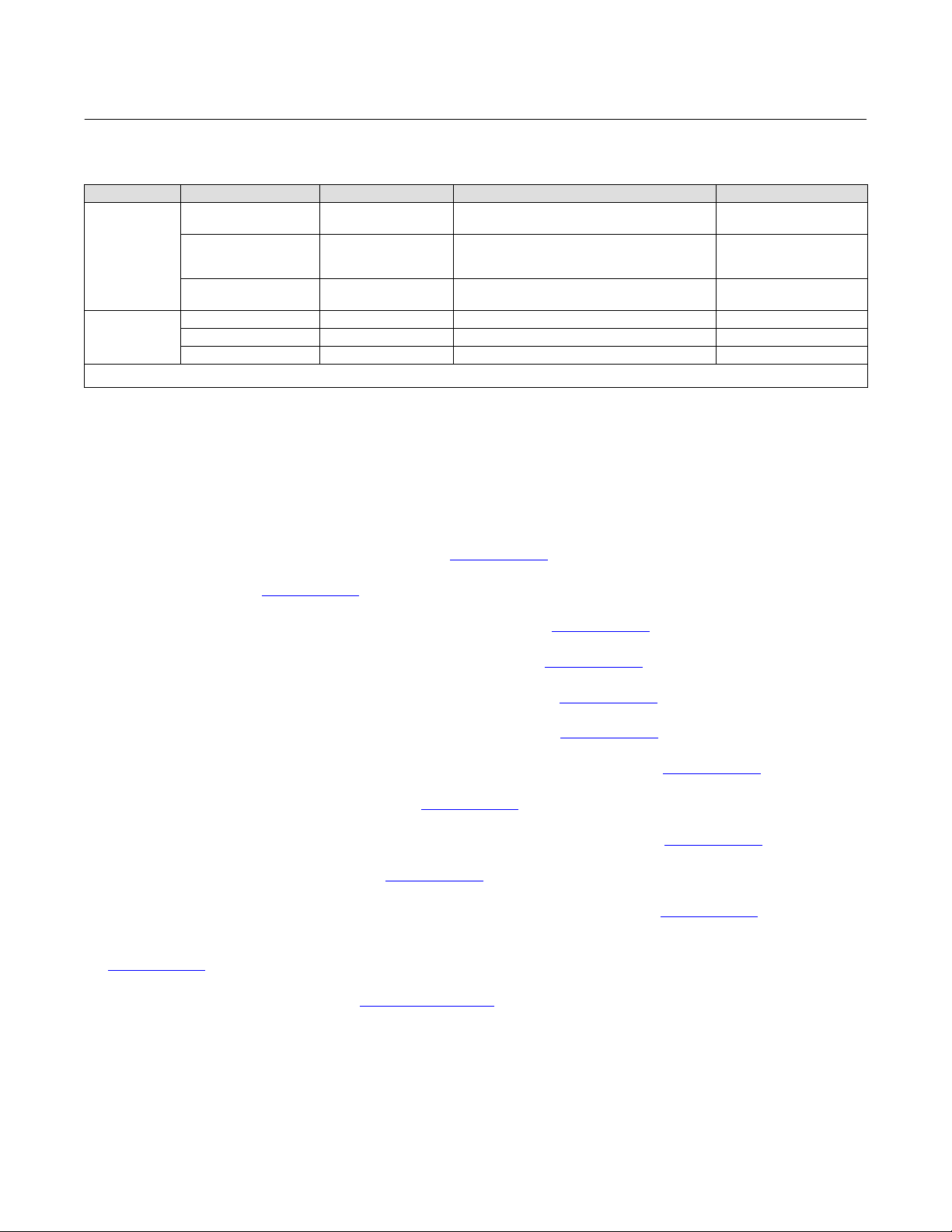
Table 1‐1. Specifications
Introduction and Specifications
July 2020
Available Configurations
J Integral mounting to the Fisher GX Control Valve
and Actuator System
J Quarter-turn rotary applications
J Sliding-stem applications
The DVC2000 digital valve controller can also be
mounted on other actuators that comply with IEC
60534-6-1, IEC 60534-6-2, VDI/VDE 3845 and
NAMUR mounting standards.
Input Signal
Analog Input Signal: 4-20 mA DC, nominal; split
ranging available
Minimum Voltage: Voltage available at instrument
terminals must be 8.5 volts for analog control, 9.0
volts for HART communication
Maximum Voltage: 30 volts DC
Minimum Control Current: 4.0 mA (below 3.5 mA
may cause microprocessor restart)
Overcurrent Protection: Input circuitry limits current
to prevent internal damage
Reverse Polarity Protection: No damage occurs from
reversal of loop current
Output Signal
Pneumatic signal as required by the actuator, up to
full supply pressure
Minimum Span: 0.5 bar (7 psig)
Maximum Span: 7 bar (101 psig)
Action: Single Acting, direct
Supply Pressure
(1)
Recommended: 0.5 bar (7 psig) greater than the
maximum actuator requirements
Maximum: 7 bar (101 psig)
Supply pressure medium must be clean, dry air or
noncorrosive gas
Per ISA Standard 7.0.01
A maximum 40 micrometer particle size in the air
system is acceptable. Further filtration down to 5
micrometer particle size is recommended. Lubricant
content is not to exceed 1 ppm weight (w/w) or
volume (v/v) basis. Condensation in the air supply
should be minimized
Per ISO 8573-1
Maximum particle density size: Class 7
Oil content: Class 3
Pressure Dew Point: Class 3 or at least 10_C less than
the lowest ambient temperature expected
-continued-
Temperature Limits
(1)
-40 to 85_C (-40 to 185_F). LCD may not be readable
below -20_C (-4 _F).
Air Consumption
Supply pressure:
At 1.5 bar (22 psig)
At 4 bar (58 psig)
Air Capacity
(2)
(3)
: 0.06 normal m3/h (2.3 scfh)
(4)
: 0.12 normal m3/h (4.4 scfh)
(2)
Supply pressure:
(3)
At 1.5 bar (22 psig)
At 4 bar (58 psig)
: 4.48 normal m3/h (167 scfh)
(4)
: 9.06 normal m3/h (338 scfh)
Independent Linearity
±0.5% of output span
Electromagnetic Compatibility
Meets EN 61326-1:2013
Immunity—Industrial locations per Table 2 of the
EN 61326-1 standard. Performance is shown
in table 1‐2 below
Emissions—Class A
ISM equipment rating: Group 1, Class A
Tested to NAMUR NE21 requirements.
Vibration Testing Method
Tested per ANSI/ISA 75.13.01 Section 5.3.5. A
resonant frequency search is performed on all three
axes. The instrument is subjected to the ISA specified
1/2 hour endurance test at each major resonance,
plus an additional two million cycles.
Input Impedance
The input impedance of the DVC2000 active
electronic circuit is not purely resistive. For
comparison to resistive load specifications, an
equivalent impedance of 450 ohms may be used. This
value corresponds to 9 V @ 20 mA.
Electrical Classification
Hazardous Area:
CSA—Intrinsically Safe and Non-incendive
FM—Intrinsically Safe and Non-incendive
ATEX—Intrinsically Safe
IECEx—Intrinsically Safe
5

Introduction and Specifications
July 2020
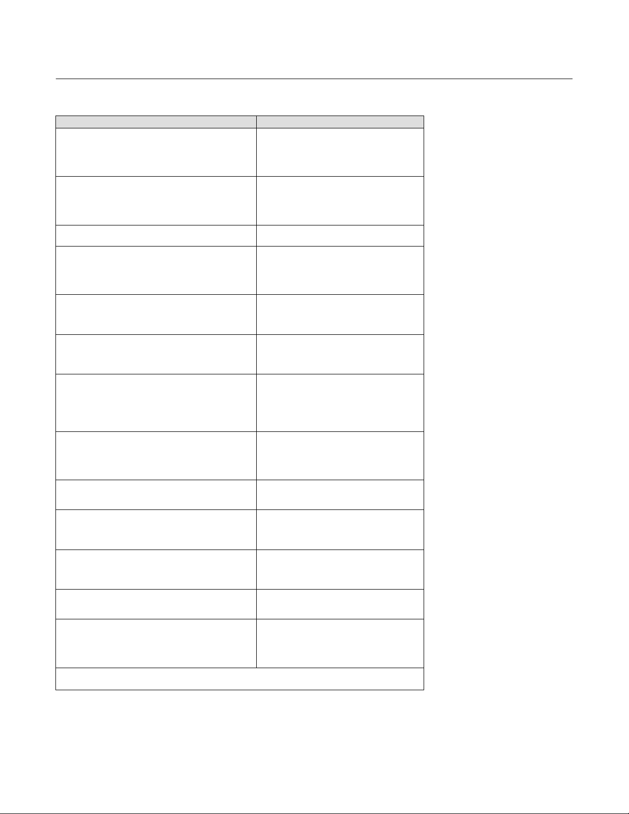
Table 1‐1. Specifications (continued)
Instruction Manual
D103176X012
Electrical Housing:
CSA—IP66 and Type 4X
FM, ATEX, IECEx—IP66
Other Classifications/Certifications
CUTR— Customs Union Technical Regulations
(Russia, Kazakhstan, Belarus, and Armenia)
ESMA— Emirates Authority for Standardization and
Metrology - ECAS-Ex (UAE)
INMETRO—National Institute of Metrology, Quality
and Technology (Brazil)
KGS— Korea Gas Safety Corporation (South Korea)
NEPSI—National Supervision and Inspection Centre
for Explosion Protection and Safety of
Instrumentation (China)
PESO CCOE— Petroleum and Explosives Safety
Organisation - Chief Controller of Explosives (India)
SABS— South African Bureau of Standards (South
Africa)
Contact your Emerson sales office
for
classification/certification specific information
Connections
Standard
Supply and Output Pressure: G1/4 internal
Electrical: M20 internal
Optional
Supply and Output Pressure: 1/4 NPT internal
Electrical: 1/2 NPT internal
Shaft Rotation
otary actuators with rated travel between 45
R
degrees and 180 degrees
Mounting
Designed for direct actuator mounting. For
weatherproof housing capability, the vent must be
positioned at the lowest point of the instrument.
Weight
1.5 kg (3.3 lbs)
Options
J Airset: 67CFR with filter
Language Packs:
J Standard: English, German, French, Italian, Spanish,
Japanese, Chinese, Portuguese, Russian, Polish, and
Czech
J Optional: English, German, French, Italian, Spanish,
Japanese, Chinese, and Arabic
J Pipe-away vent
J Limit Switches: Two isolated switches,
configurable throughout calibrated travel range
Supply Voltage: 5-30 VDC
OFF State: 0.5 to 1.0 mA
ON State: 3.5 to 4.5 mA (above 5 V)
Reference Accuracy: 2.5% of travel span
J Transmitter: 4-20 mA output, isolated
(5)
Supply Voltage: 8-30 VDC
Fault Indication: offrange high or low
Reference Accuracy: 1% of travel span
(5)
Materials of Construction
Declaration of SEP
Fisher Controls International LLC declares this
Housing and Cover: A03600 low copper aluminum
alloy
Elastomers: nitrile, fluorosilicone
product to be in compliance with Article 4 paragraph
3 of the PED Directive 2014/68/EU. It was designed
and manufactured in accordance with Sound
Engineering Practice (SEP) and cannot bear the CE
marking related to PED compliance.
Stem Travel
Linear actuators with rated travel between 6.35 mm
(0.25 inch) and 606 mm (23.375 inches)
1. The pressure/temperature limits in this document and any applicable standard or code limitation should not be exceeded. Note: Temperature limits vary based on hazardous area approval.
2. Normal m
3. Low pressure relay: 0 to 3.3 bar (0 to 49 psig).
4. High pressure relay: 3.4 to 7.0 bar (50 to 102 psig).
5. Typical values when calibrated at temperature.
6
3
/hour - Normal cubic meters per hour at 0_C and 1.01325 bar, absolute. Scfh - Standard cubic feet per hour at 60_F and 14.7 psia.
However, the product may bear the CE marking to
indicate compliance with other applicable European
Community Directives.
Instruction Manual
(1)
D103176X012
Introduction and Specifications
Table 1‐2. EMC Summary Results—Immunity
Port Phenomenon Basic Standard Test Level Performance Criteria
Electrostatic discharge
(ESD)
Enclosure
I/O signal/control
Performance criteria is + / - 1% effect.
1. A = No degradation during testing. B = Temporary degradation during testing, but is self-recovering.
Radiated EM field IEC 61000-4-3
Rated power frequency
magnetic field
Burst (fast transients) IEC 61000-4-4 $1 kV A
Surge IEC 61000-4-5 $1 kV (line to ground only, each) B
Conducted RF IEC 61000-4-6 150 kHz to 80 MHz at 10 Vrms A
IEC 61000-4-2
IEC 61000-4-8 30 A/m at 50 Hz, 60 sec A
6 kV contact
8 kV air
80 to 1000 MHz @ 10V/m with 1 kHz AM at 80%
1400 to 2000 MHz @ 3V/m with 1 kHz AM at 80%
2000 to 2700 MHz @ 1V/m with 1 kHz AM at 80%
Related Documents
Other documents containing information related to the DVC2000 digital valve controller include:
July 2020
B
A
D DVC2000 Digital Valve Controller Quick Start Guide (D103203X012
D Bulletin 62.1:DVC2000 (D103167X012
)
D CSA Hazardous Area Approvals - DVC2000 Digital Valve Controllers (D104224X012
D FM Hazardous Area Approvals - DVC2000 Digital Valve Controllers (D104225X012
D ATEX Hazardous Area Approvals - DVC2000 Digital Valve Controllers (D104226X012
D IECEx Hazardous Area Approvals - DVC2000 Digital Valve Controllers (D104227X012
D INMETRO Hazardous Area Approvals for FIELDVUE DVC2000 Digital Valve Controller (D103780X012
D FIELDVUE Digital Valve Controller Split Ranging (D103262X012
D Using FIELDVUE Instruments with the Smart HART Loop Interface and Monitor (HIM) (D103263X012
D Audio Monitor for HART Communications (D103265X012
)
D HART Field Device Specification - Fisher FIELDVUE DVC2000 Digital Valve Controller (D103783X012
)
)
)
)
)
)
)
)
)
D Using the HART Tri-Loop HART-to-Analog Signal Converter with Fisher FIELDVUE Digital Valve Controllers
(D103267X012
These documents are available from your Emerson sales office
)
or at Fisher.com.
7

Introduction and Specifications
July 2020
Instruction Manual
D103176X012
Educational Services
For information on available courses for the DVC2000 digital valve controller, as well as a variety of other products,
contact:
Emerson Automation Solutions
Educational Services - Registration
Phone: 1-641-754-3771 or 1-800-338-8158
E-mail: education@emerson.com
emerson.com/fishervalvetraining
8

Instruction Manual
D103176X012
Detailed Setup and Calibration
July 2020
Section 2 Detailed Configuration and Calibration via HART
Communication
2‐2‐
Detailed Setup
The DVC2000 digital valve controller has the capability to communicate via the HART protocol. This section describes
the advanced features that can be accessed with the Field Communicator. Table 2‐1 lists the default settings for a
standard factory configuration. Table 2‐2 provides the actuator information required to setup and calibrate the
instrument.
Setting Modes
Field Communicator Setup & Diag > Detailed Setup > Mode (1-2-1)
Instrument Mode
You can change the instrument mode by selecting Instrument Mode from the Mode menu, or press the Hot Key and
select Instrument Mode.
Instrument Mode allows you to either take the instrument Out Of Service or place it In Service. Taking the instrument
Out Of Service allows you to perform instrument calibration and also allows you to change setup variables that affect
control, provided the calibration/configuration protection is properly set. See Setting Protection.
Note
Some changes that require the instrument to be taken Out Of Service will not take effect until the instrument is placed back In
Service or the instrument is restarted.
Control Mode
You can change the control mode by selecting Control Mode from the Mode menu, or press the Hot Key and select
Control Mode.
Control Mode lets you define where the instrument receives its set point. Follow the prompts on the Field
Communicator display to choose one of the following control modes: Analog or Digital.
Choose Analog if the instrument is to receive its set point over the 4-20 mA loop. Normally the instrument control
mode is Analog.
Choose Digital if the instrument is to receive its set point digitally, via the HART communications link.
A third mode, Test, is also displayed. Normally the instrument should not be in the Test mode. The Field
Communicator automatically switches to this mode whenever it needs to stroke the valve, for example during
9

Detailed Setup and Calibration
July 2020
Instruction Manual
D103176X012
calibration or stroke valve. However, if you abort from a procedure where the instrument is in the Test mode, it may
remain in this mode. To take the instrument out of the Test mode, select Control Mode then select either Analog or
Digital.
Restart Control Mode
Restart Control Mode (Restart Cont Mode) lets you choose which operating mode you want the instrument to be in
after a restart. Follow the prompts on the Field Communicator display to define the restart control mode as Resume
Last, Analog, or Digital.
Restarting the Instrument
Restart resets the instrument in the same manner as when power to the instrument is interrupted. When Restart is
issued, all of the newly entered configuration variables become active. Otherwise, they may not take effect until the
instrument is placed In Service.
Burst Mode
Enabling burst mode provides continuous communication from the digital valve controller. Burst mode applies only to
the transmission of burst mode data (analog input, travel target, pressure, and travel) and does not affect the way
other data is accessed.
Access to information in the instrument is normally obtained through the poll/response of HART communication. The
Field Communicator or the control system may request any of the information that is normally available, even while
the instrument is in burst mode. Between each burst mode transmission sent by the instrument, a short pause allows
the Field Communicator or control system to initiate a request. The instrument receives the request, processes the
response message, and then continues “bursting” the burst mode data.
There are four burst mode commands. Command 3 is recommended for use with the Rosemount
Tri-Loop
™
HART-to-analog signal converter. The other three are not used at this time.
™
333 HART
Command 3 provides the following variables:
D Primary variable—analog input in % or mA,
D Secondary variable—travel target (valve set point) in % of ranged travel,
D Tertiary variable—output pressure in psig, bar, or kPa,
D Quaternary variable—travel in % of ranged travel.
To enable burst mode select Mode > Burst > Burst Enable. To send a burst mode command, select Burst Command.
Burst mode must be enabled before you can change the burst mode command.
10
Instruction Manual
(1)
(2)
(2)
D103176X012
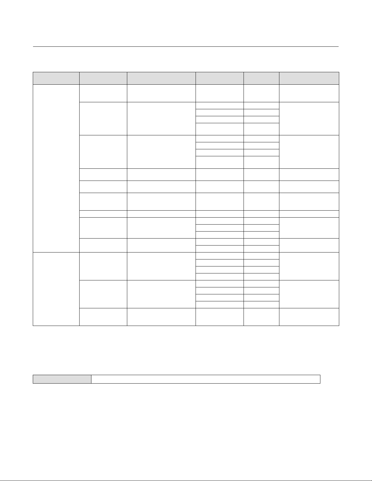
Table 2‐1. Factory Default Detailed Setup Parameters
Setup Parameter Default Setting
Control Mode
Restart Control Mode
Burst Mode Enabled
Burst Mode Command
HART Tag
Message
Description
Date
Valve Serial Number
Polling Address
Max Supply Pressure
Zero Control Signal
Analog Input Units
Analog In Range High
Analog In Range Low
Travel Range High
Travel Range Low
Pressure Units
Temperature Units
Input Characteristic
Setpoint Filter Time
Travel Limit High
Travel Limit Low
Travel Cutoff High
Travel Cutoff Low
Minimum Opening Time
Minimum Closing Time
Integral Gain
Integral Deadband
Travel Hi/Lo Alert Enabled
Travel Hi Hi/Lo Lo Alert Enabled
Travel Alert High Point
Travel Alert Low Point
Travel Alert High-High Point
Travel Alert Low-Low Point
Travel Alert Deadband
Travel Deviation Alert Enable
Travel Deviation Alert Point
Travel Deviation Time
Cycle Counter Alert Enable
Cycle Counter Alert Point
Cycle Counter Deadband
Cycle Counter
Travel Accumulator Alert Enable
Travel Accumulator Alert Point
Travel Accumulator Deadband
Travel Accumulator
Drive Alert Enable
Flash ROM Fail
Ref Voltage Fail
Drive Current Fail
Critical NVM Fail
Temperature Sensor Fail
Pressure Sensor Fail
Travel Sensor Fail
1. The settings listed are for standard factory configuration. DVC2000 instruments can also be ordered with custom configuration
settings. For the default custom settings, refer to the order requisition.
2. If the instrument is shipped mounted on an actuator, these values depend upon the actuator on which the instrument is mounted.
Analog
Resume Last
No
As specified on order
Factory Calibration Date
3
Blank
Blank
Blank
0
100
(2)
Open
mA
20 mA
4.0 mA
100%
0%
PSI
F
Linear
Filter Off
125%
-25%
99.5%
0.5%
0 secs
0 secs
1 repeat/minute
0.5%
No
No
125%
-25%
125%
-25%
1%
Yes
7%
5 secs
No
2,147,483,646
3%
0
No
2,147,483,646%
3%
0
No
No
No
No
No
No
No
No
Detailed Setup and Calibration
July 2020
11
Detailed Setup and Calibration
July 2020
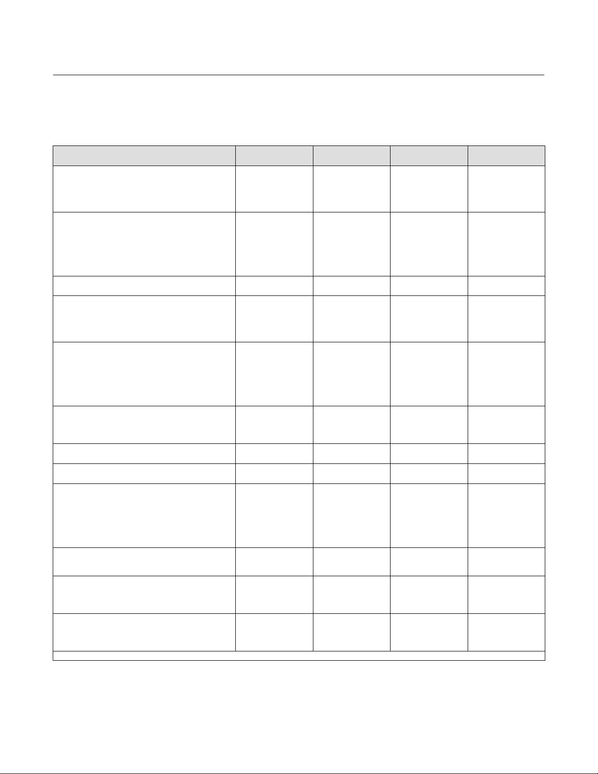
Table 2‐2. Actuator Information for Setup
Actuator
Manufacturer
Fisher
Baumann
Actuator Model Actuator Style Actuator Size
585C & 585CR
657 Spring & Diaphragm
667 Spring & Diaphragm
1051 & 1052 Spring & Diaphragm
1066SR Piston Sgl w/Spring
3024 Spring & Diaphragm
3025 Spring & Diaphragm P460, P462, P900 Undefined Rotary
GX Spring & Diaphragm
GX 3-Way Spring & Diaphragm
Air to Extend Spring & Diaphragm
Air to Retract Spring & Diaphragm
Rotary Spring & Diaphragm
Piston single w/spring. See
actuator instruction manual and
nameplate.
25, 50, 60, 68,
80, 100, 130
30, 30i G
34, 34i, 40, 40i I
45, 45i, 50, 50i J
46, 46i, 60, 60i, 70,
70i & 80-100
30, 30i G
34, 34i, 40, 40i I
45, 45i, 50, 50i J
46, 46i, 60, 60i, 70,
70i, 76, 76i & 80-100
20, 30, 33,
40, 60, 70
20
27, 75
GA 1.21
GA 1.31
GA 1.41
225 G
750 I
1200 K
225 G
750 I
16 C
32 D
54 Undefined
70 H
16 C
32 D
54 Undefined
70 H
10
25
54
Instruction Manual
D103176X012
Starting
Tuning Set
Undefined
Undefined
Undefined
Undefined Rotary
Undefined Rotary
Undefined SStem-Standard
Undefined
Undefined
G
Feedback Connection
SStem-Standard for travels
up to 4 inches. SStem-
Roller for longer travels
SStem-Standard
SStem-Standard
SStem-Standard
SStem-Standard
SStem-Standard
SStem-Standard
Rotary
Setting Protection
Field Communicator Setup & Diag > Detailed Setup > Protection (1-2-2)
Some setup parameters may require changing the protection with the Field Communicator.
Two levels of protection are available:
D None—Neither setup nor calibration is protected. Allows changing calibration and setup parameters.
D Config & Calib—Both setup and calibration are protected. Prohibits changing calibration and protected setup
parameters.
12
Instruction Manual
D103176X012
Detailed Setup and Calibration
July 2020
Table 2‐3 lists configurable parameters in the instrument and the requirements for modifying these parameters, in
terms of instrument mode and protection.
Table 2‐3. Conditions for Modifying FIELDVUE DVC2000 Digital Valve Controller Parameters
Parameters
Control Mode
Restart Ctrl Mode
Burst Mode Enable
Burst Mode Command
Protection
HART Tag
Message
Description
Date
Valve Serial Num
Inst Serial Num
Polling Address
Max Supply Pressure
Zero Ctrl Signal
Analog In Units
Input Range High
Input Range Low
Pressure Units
Temp Units
Tuning Set
Prop Gain
Velocity Gain
MLFB Gain
Input Char
Define Custom Char
Set Pt Filter Time
Tvl Limit High
Tvl Limit Low
Tvl Cutoff High
Tvl Cutoff Low
Min Opening Time
Min Closing Time
Integral Gain
Integral Deadband
Tvl Hi/Lo Enab
Tvl HH/LL Enab
Tvl Alert Hi Pt
Tvl Alert Lo Pt
Tvl Alert HiHi Pt
Tvl Alert LoLo Pt
Tvl Alrt DB
Tvl Dev Alrt Enab
Tvl Dev Alrt Pt
Tvl Dev Time
Cycl Cnt Alrt Enab
Cycl Count Alrt Pt
Cycl Count DB
Cycl Count
Tvl Acum Alrt Enab
Tvl Acum Alrt Pt
Tvl Acum DB
Tvl Acum
n—indicates parameter may be modified for instrument mode and protection shown.
In Service/
Config Protected
- - -
- - -
- - -
- - -
- - -
- - -
- - -
- - -
- - -
- - -
- - -
- - -
- - -
- - -
- - -
- - -
- - -
- - -
- - -
- - -
- - -
- - -
- - -
- - -
- - -
- - -
- - -
- - -
- - -
- - -
- - -
n
n
n
n
n
n
n
n
n
n
n
n
n
n
n
n
n
n
n
n
n
-Continued-
In Service/
Config Unprotected
- - -
- - -
n
- - -
n
n
n
n
n
n
- - -
- - -
- - -
- - -
- - -
- - -
- - -
- - -
n
n
n
n
n
- - -
- - -
- - -
- - -
- - -
- - -
- - -
- - -
- - -
n
n
n
n
n
n
n
n
n
n
n
n
n
n
n
n
n
n
n
n
Out of Service/
Config Protected
n
- - -
n
- - -
n
- - -
- - -
- - -
- - -
- - -
- - -
- - -
- - -
- - -
- - -
- - -
- - -
- - -
n
- - -
- - -
- - -
- - -
- - -
- - -
- - -
- - -
- - -
- - -
- - -
- - -
- - -
- - -
- - -
n
n
n
n
n
n
n
n
n
n
n
n
n
n
n
n
n
n
Out of Service/
Config Unprotected
n
n
n
n
n
n
n
n
n
n
n
n
n
n
n
n
n
n
n
n
n
n
n
n
n
n
n
n
n
n
n
n
n
n
n
n
n
n
n
n
n
n
n
n
n
n
n
n
n
n
n
n
13
Detailed Setup and Calibration
July 2020
Instruction Manual
D103176X012
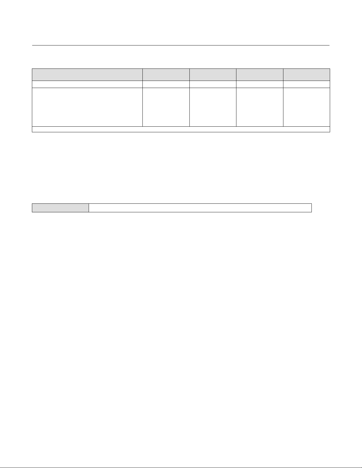
Table 2‐3. Conditions for Modifying FIELDVUE DVC2000 Digital Valve Controller Parameters
Parameters
Drive Alert Enable n n n n
Flash ROM Fail
Ref Voltage Fail
Drive Current Fail
Critical NVM Fail
Temp Sensor Fail
Press Sensor Fail
Tvl Sensor Fail
n—indicates parameter may be modified for instrument mode and protection shown.
In Service/
Config Protected
- - -
- - -
- - -
- - -
- - -
- - -
- - -
In Service/
Config Unprotected
- - -
- - -
- - -
- - -
- - -
- - -
- - -
Out of Service/
Config Protected
- - -
- - -
- - -
- - -
- - -
- - -
- - -
Out of Service/
Config Unprotected
n
n
n
n
n
n
n
To change an instrument's protection, press the Hot key on the Field Communicator display window and select
Protection or select Protection from the Detailed Setup menu. Select the desired level of protection. Follow the prompts
on the Field Communicator display to set the protection level.
General Information
Field Communicator Setup & Diag > Detailed Setup > General (1-2-3)
Follow the prompts on the Field Communicator to enter or view information in the following fields:
D HART Tag—Enter an up to 8 character HART tag for the instrument. The HART tag is the easiest way to distinguish
between instruments in a multi-instrument environment. Use the HART tag to label instruments electronically
according to the requirements of your application. The tag you assign is automatically displayed when the Field
Communicator establishes contact with the digital valve controller at power-up.
D Message—Enter any message with up to 32 characters. Message provides the most specific user-defined means for
identifying individual instruments in multi-instrument environments.
D Descriptor—Enter a descriptor for the application with up to 16 characters. The descriptor provides a longer
user-defined electronic label to assist with more specific instrument identification than is available with the HART
tag.
D Date—Enter a date with the format MM/DD/YY. Date is a user-defined variable that provides a place to save the date
of the last revision of configuration or calibration information.
D Valve Serial Num—Enter the serial number for the valve in the application with up to 12 characters.
D Inst Serial Num—Enter the serial number on the instrument nameplate, up to 12 characters.
D Polling Address—If the digital valve controller is used in point-to-point operation, the Polling Address is 0. When
several devices are connected in the same loop, such as for split ranging, each device must be assigned a unique
polling address. The Polling Address is set to a value between 0 and 15. To change the polling address the
instrument must be Out Of Service.
For the Field Communicator to be able to communicate with a device whose polling address is not 0, it must be
configured to automatically search for all or specific connected devices.
D LUI Language—Select the language to be displayed on the local user interface; English, French, German, Italian,
Spanish, Chinese and Japanese.
14
Instruction Manual
D103176X012
Detailed Setup and Calibration
July 2020
Measured Variable Units and Ranges
Field Communicator Setup & Diag > Detailed Setup > Measured Var (1-2-4)
Follow the prompts on the Field Communicator to define the following measured variables units and ranges:
D Analog In Units—Permits defining the Analog Input Units in mA or percent of 4-20 mA range.
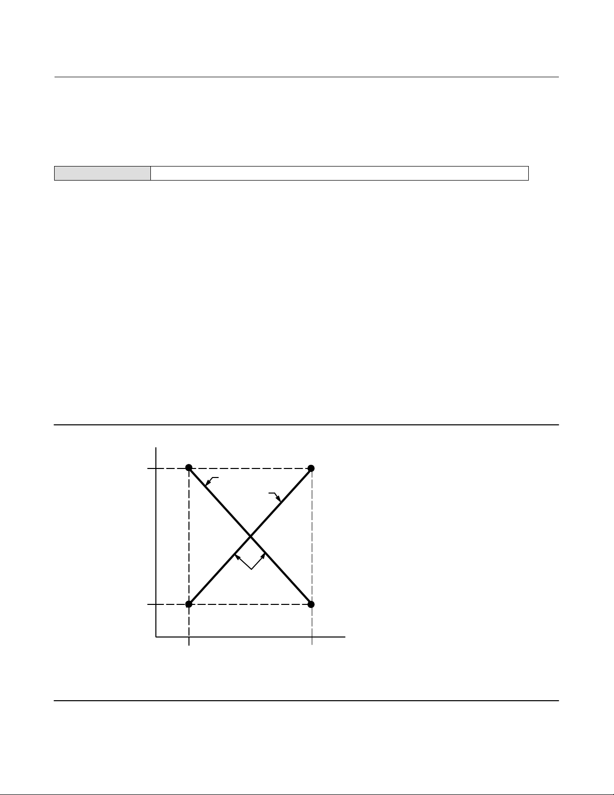
D Input Range Hi—Permits setting the Input Range High value. Input Range High should correspond to Travel Range
High, if the Zero Control Signal is configured as closed. If the Zero Control Signal is configured as open, Input Range
High corresponds to Travel Range Low. See figure 2‐1.
D Input Range Lo—Permits setting the Input Range Low value. Input Range Low should correspond to Travel Range
Low, if the Zero Control Signal is configured as closed. If the Zero Control Signal is configured as open, Input Range
Low corresponds to Travel Range High. See figure 2‐1.
D Pressure Units—Defines the output and supply pressure units in either psi, bar, or kPa.
D LUI Pressure Units—Enter the pressure units displayed on the local user interface; psi, bar, or kPa.
D Temp Units—Degrees Fahrenheit or Celsius. The temperature measured is from a sensor mounted on the digital
valve controller's printed wiring board.
Figure 2‐1. Calibrated Travel to Analog Input Relationship
TRAVEL
A6531-1
RANGE
HIGH
CALIBRATED TRAVEL, %
TRAVEL
RANGE
LOW
INPUT RANGE
LOW
NOTE:
ZCS = ZERO CONTROL SIGNAL
ZCS = OPEN
ZCS = CLOSED
THE SHAPE OF
THESE LINES DEPENDS ON
THE INPUT CHARACTERISTICS
LINEAR CHARACTERISTIC SHOWN
ANALOG INPUT
MA OR % OF 4-20 MA
INPUT RANGE
HIGH
15
Detailed Setup and Calibration
July 2020
Instruction Manual
D103176X012
Actuator and Valve Information
Field Communicator Setup & Diag > Detailed Setup > Actuator & Valve (1-2-5)
Follow the prompts on the Field Communicator to edit or view information in the following fields:
D Max Supply Press—Enter the maximum supply pressure in psi, bar, or kPa, depending on what was selected for
pressure units.
Note
If the actual measured pressure exceeds this setting by 25%, the Output A pressure measurement will not be displayed.
D Actuator Style—Enter the actuator style, spring and diaphragm, piston double-acting without spring, piston
single-acting with spring, or piston double-acting with spring.
D Valve Style—Enter the valve style, rotary or sliding-stem
D Zero Control Signal—Identifies whether the valve is fully open or fully closed when the input is 0%. If you are unsure
how to set this parameter, disconnect the current source to the instrument. The resulting valve travel is the Zero
Control Signal. (With direct-acting digital valve controllers, disconnecting the current source is the same as setting
the output pressure to zero.)
Setting Response
Field Communicator Setup & Diag > Detailed Setup > Response Control (1-2-6)
Follow the prompts on the Field Communicator to configure the following response control parameters:
WARNING
Changes to the tuning set may cause the valve/actuator assembly to stroke. To avoid personal injury and property damage
caused by moving parts, keep hands, tools, and other objects away from the valve/actuator assembly.
D Tuning Set—There are eleven tuning sets to choose from. Each tuning set provides a preselected value for the digital
valve controller gain settings. Tuning set C provides the slowest response and M provides the fastest response.
Table 2‐4 lists the proportional gain, velocity gain, and minor loop feedback gain values for preselected tuning sets.
16
Instruction Manual
D103176X012
Detailed Setup and Calibration
July 2020
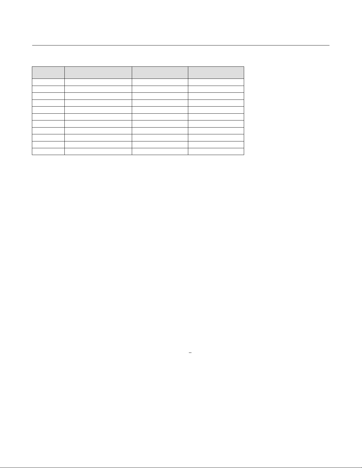
Table 2‐4. Gain Values for Preselected Turning Sets
Tuning Set Proportional Gain Velocity Gain
C 5 2 55
D 6 2 55
E 7 2 55
F 8 2 52
G 9 2 49
H 10 2 46
I 11 2 44
J 12 1 41
K 14 1 38
L 16 1 35
M 18 1 35
Minor Loop Feedback
Gain
D Damping Factor—If after selecting a tuning set the valve travel overshoot is excessive or unsatisfactory, the damping
factor allows you to either decrease damping to allow more overshoot, or increase damping to decrease the
overshoot.
D Expert Tuning Gains—With Expert Tuning, you can specify the proportional gain, velocity gain, and minor loop
feedback gain.
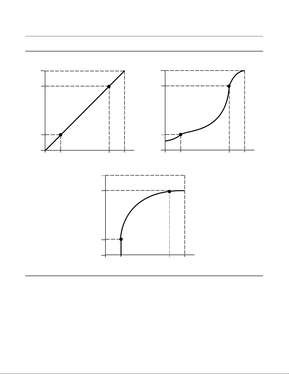
D Input Char—Defines the relationship between the travel target and ranged set point. Ranged set point is the input to
the characterization function. If the zero control signal equals closed, then a set point of 0% corresponds to a ranged
input of 0%. If the zero control signal equals open, a set point of 0% corresponds to a ranged input of 100%. Travel
target is the output from the characterization function.
You can select from the three fixed input characteristics shown in figure 2‐2 or you can select a custom
characteristic. Figure 2‐2 shows the relationship between the travel target and ranged set point for the fixed input
characteristics, assuming the Zero Control Signal is configured as closed.
You can specify 21 points on a custom characteristic curve. Each point defines a travel target, in % of ranged travel,
for a corresponding set point, in % of ranged set point. Set point values range from -6.25% to 106.25%. Before
modification, the custom characteristic is linear.
With input characterization you can modify the overall characteristic of the valve and instrument combination.
Selecting an equal percentage, quick opening, or custom (other than the default of linear) input characteristic
modifies the overall valve and instrument characteristic. However, if you select the linear input characteristic, the
overall valve and instrument characteristic is the characteristic of the valve, which is determined by the valve trim
(i.e., the plug or cage).
D Custom Char Table—To define a custom input characteristic, s
elect Custom Char Table. Select the point you wish to
define (1 to 21), then enter the desired set point value. Press Enter then enter the desired travel target for the
corresponding set point. When finished, select point 0 to return to the Response Control menu.
17
Detailed Setup and Calibration
July 2020
Instruction Manual
D103176X012
Figure 2‐2. Travel Target Versus Ranged Set Point, for Various Input Characteristics (Zero Control Signal = Closed)
125
100
Travel Target, %
0
-25
−25
Ranged Set Point, %
0 125
100
Input Characteristic = Linear
125
100
125
100
Travel Target, %
0
-25
−25
Ranged Set Point, %
0 125
100
Input Characteristic = Equal Percentage
Travel Target, %
0
A6535-1
-25
−25
Input Characteristic = Quick Opening
Ranged Set Point, %
0 125
100
D Setpt Filter Time—Time constant for the set point filter, in seconds. The set point filter slows the response of the
digital valve controller and is typically used with noisy or fast processes. The filter provides improved closed loop
process control. To disable the filter, set the time constant to 0 seconds.
D Limits and Cutoff
Travel Limit Hi—Defines the high limit for the travel in percent (%) of ranged travel. It is the maximum allowable
travel (in percent of ranged travel) for the valve. During operation, the travel target will not exceed this limit. When
a Travel Limit High is set, the Travel Cutoff High is deactivated, since only one of these parameters can be active.
Travel Limit High is deactivated by setting it to 125.0%.
18

Instruction Manual
D103176X012
Detailed Setup and Calibration
July 2020
Travel Limit Lo—Defines the low limit for the travel in percent (%) of ranged travel. It is the minimum allowable travel
(in percent of ranged travel) for the valve. During operation, the travel target will not exceed this limit. When a
Travel Limit Low is set, the Travel Cutoff Low is deactivated, since only one of these parameters can be active. Travel
Limit Low is deactivated by setting it to -25.0%.
Travel Cutoff Hi—Defines the high cutoff point for the travel in percent (%) of ranged travel. Above this cutoff, the
travel target is set to 123.0% of the ranged travel. When a Travel Cutoff High is set, the Travel Limit High is
deactivated, since only one of these parameters can be active. Travel Cutoff High is deactivated by setting it to
125.0%.
Travel Cutoff Lo—Defines the low cutoff point for the travel. Travel Cutoff Low can be used to ensure proper seat load
is applied to the valve. When below the travel cutoff low, the output is set to zero or to full supply pressure,
depending upon the zero control signal. A Travel Cutoff Low of 0.5% is recommended to help ensure maximum
shutoff seat loading.
When a Travel Cutoff Low is set, the Travel Limit Low is deactivated, since only one of these parameters can be
active. Travel Cutoff Low is deactivated by setting it to -25.0%.
D Min Open/Close
Min Opening Time—Minimum Opening Time is configured in seconds and defines the minimum time for the travel to
increase the entire ranged travel. This rate is applied to any travel increases. A value of 0.0 seconds deactivates this
feature and allows the valve to stroke open as fast as possible. This parameter should be set to 0 in firmware 1, 2, 3,
and 4.
Min Closing Time—Minimum Closing Time is configured in seconds and defines the minimum time for the travel to
decrease the entire ranged travel. This rate is applied to any travel decreases. A value of 0.0 seconds deactivates this
feature and allows the valve to stroke closed as fast as possible. This parameter should be set to 0 in firmware 1, 2,
3, and 4.
D Integral Settings
Enab Int Control—Select Yes or No
Integral Gain—By setting this value to 0.0 the positioner integrator is disabled. Any other value will provide reset
action to improve static performance.
Integral Dead Zone—When the travel target and actual target deviate by less than this amount, the integrator is
automatically disabled. This prevents the positioner integrator from fighting with the process controller integrator
which may result in valve oscillation.
Setting Alerts
Field Communicator Setup & Diag > Detailed Setup > Alerts (1-2-7)
The following menus are available for configuring Alerts. Items on the menus may be changed with the instrument In
Service. Protection does not need to be removed (no need to set to None). Alerts are not processed when a Diagnostic
is in progress. Follow the prompts on the Field Communicator display to configure alerts.
Note
Alerts are not available with instrument level AC.
19
Detailed Setup and Calibration
July 2020
Instruction Manual
D103176X012
Setting Travel Alerts
Setting High, High-High, Low and Low-Low Alerts
Follow the prompts on the Field Communicator to set the following travel alerts:
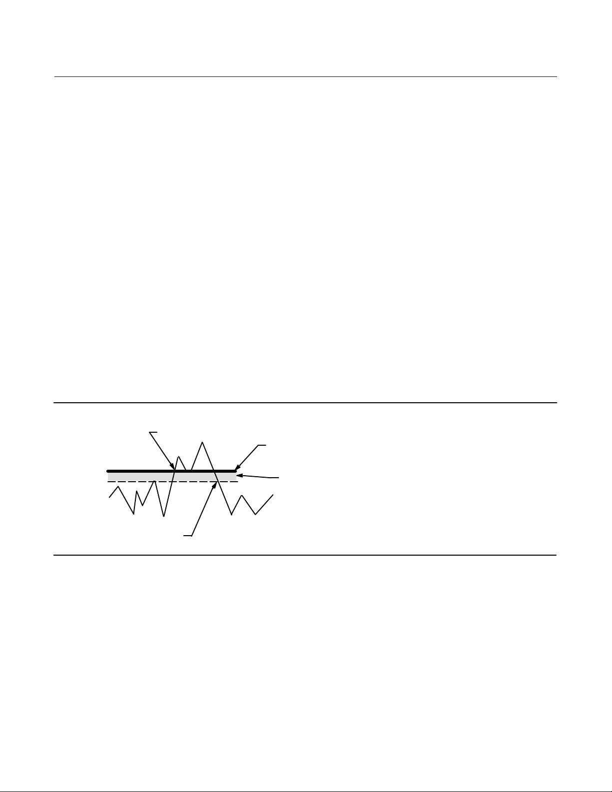
D Tvl Hi/Lo Enab—Yes or No. Travel Hi/Lo Enable activates checking of the ranged travel against the Travel Alert High
and Low Points. Travel Alert Hi is set if the ranged travel rises above the alert high point. Once the alert is set, the
ranged travel must fall below the alert high point by the Travel Alert Deadband before the alert is cleared. See figure
2‐3.
Travel Alert Lo is set if the ranged travel falls below the alert low point. Once the alert is set, the ranged travel must
rise above the alert low point by the Travel Alert Deadband before the alert is cleared. See figure 2‐3.
D Tvl HH/LL Enab—Yes or No. Travel HH/LL Enable activates checking of the ranged travel against the Travel Alert
High-High and Low-Low Points. Travel Alert Hi Hi is set if the ranged travel rises above the alert high-high point.
Once the alert is set, the ranged travel must fall below the alert high-high point by the Travel Alert Deadband before
the alert is cleared. See figure 2‐3.
Travel Alert Lo Lo is set if the ranged travel falls below the alert low-low point. Once the alert is set, the ranged travel
must rise above the alert low-low point by the Travel Alert Deadband before the alert is cleared. See figure 2‐3.
Figure 2‐3. Travel Alert Deadband
ALERT IS SET
TRAVEL ALERT
HIGH POINT
TRAVEL ALERT
DEADBAND
A6532
ALERT IS CLEARED
D Tvl Alert Hi Pt—Travel Alert High Point is the value of the travel, in percent (%) of ranged travel, which, when
exceeded, sets the Travel Alert High alert.
D Tvl Alert Lo Pt—Travel Alert Low Point is the value of the travel, in percent (%) of ranged travel, which, when
exceeded, sets the Travel Alert Low alert.
D Tvl Alert Hi Hi Pt—Travel Alert High-High Point is the value of the travel, in percent (%) of ranged travel, which, when
exceeded, sets the Travel Alert Hi Hi alert.
D Tvl Alert Lo Lo Pt—Travel Alert Low-Low Point is the value of the travel, in percent (%) of ranged travel, which, when
exceeded, sets the Travel Alert Lo Lo alert.
20

Instruction Manual
D103176X012
Detailed Setup and Calibration
July 2020
D Tvl Alrt DB—Travel Alert Deadband is the travel, in percent (%) of ranged travel, required to clear a travel alert, once it
has been set. The deadband applies to both Travel Alert Hi/Lo and Travel Alert Hi Hi/Lo Lo. See figure 2‐3.
Note
The Travel Alert Deadband applies to the Travel Deviation as well as Travel Alert Hi/Lo and Travel Alert Hi Hi/Lo Lo.
Setting Travel Deviation Alert
Follow the prompts on the Field Communicator to set the following travel deviation alerts:
D Tvl Dev Alrt Enab—Yes or No. When enabled, checks the difference between the travel target and the actual travel. If
the difference exceeds the Travel Deviation Alert Point for more than the Travel Deviation Time, the Travel
Deviation Alert is set. It remains set until the difference between the travel target and the actual travel is less than
the Travel Deviation Alert Point minus the Travel Alert Deadband.
D Tvl Dev Alrt Pt—Travel Deviation Alert Point is the alert point for the difference, expressed in percent (%), between
the travel target and the actual travel. When the difference exceeds the alert point for more than the Travel
Deviation Time, the Travel Deviation Alert is set.
D Tvl Dev Time—Travel Deviation Time is the time, in seconds, that the travel deviation must exceed the Travel
Deviation Alert Point before the alert is set.
Setting Travel Accumulation Alert
Follow the prompts on the Field Communicator to set the following travel accumulation alerts:
D Tvl Acum Alrt Enab—Yes or No. Travel Accumulator Alert Enable activates checking of the difference between the
Travel Accumulator value and the Travel Accumulator Alert Point. The Travel Accumulator Alert is set when the
Travel Accumulator value exceeds the Travel Accumulator Alert Point. It is cleared after you reset the Travel
Accumulator to a value less than the alert point.
D Tvl Accum Alrt Pt—Travel Accumulator Alert Point is the value of the Travel Accumulator, in percent (%) of ranged
travel, which, when exceeded, sets the Travel Accumulator Alert.
D Tvl Accum DB—Travel Accumulator Deadband is the area around the travel reference point, in percent (%) of ranged
travel, that was established at the last increment of the accumulator. This area must be exceeded before a change
in travel can be accumulated. See figure 2‐4.
D Tvl Accum—Travel Accumulator records the total change in travel, in percent (%) of ranged travel, since the
accumulator was last cleared. The value of the Travel Accumulator increments when the magnitude of the change
exceeds the Travel Accumulator Dead- band. See figure 2‐4. You can reset the Travel Accumulator by configuring it
to zero.
21

Detailed Setup and Calibration
July 2020
Figure 2‐4. Travel Accumulator Deadband (set at 10%)
DEADBAND EXCEEDED,
NEW REFERENCE POINT
ESTABLISHED
Instruction Manual
D103176X012
DEADBAND REFERENCE POINT
DEADBAND (+/- 5%)
A6534
THIS AMOUNT OF CHANGE IS
ADDED TO THE TRAVEL
ACCUMULATOR.
Cycle Counter Alert
Follow the prompts on the Field Communicator to set the following cycle counter alerts:
D Cycl Cnt Alrt Enab—Yes or No. Cycle Counter Alert Enable activates checking of the difference between the Cycle
Counter and the Cycle Counter Alert point. The Cycle Counter Alert is set when the value exceeds the Cycle Counter
Alert point. It is cleared after you reset the Cycle Counter to a value less than the alert point.
D Cycl Cnt Alrt Pt—Cycle Counter Alert Point is the value of the Cycle Counter, in cycles, which, when exceeded, sets the
Cycle Counter Alert.
D Cycle Count DB—Cycle Counter Deadband is the area around the travel reference point, in percent (%) of ranged
travel, that was established at the last increment of the Cycle Counter. This area must be exceeded before a change
in travel direction can be counted as a cycle. See figure 2‐5.
Figure 2‐5. Cycle Counter Deadband (set at 10%)
DEADBAND EXCEEDED, AND DIRECTION
CHANGED, NEW REFERENCE POINT
ESTABLISHED
22
A6533-1
POINT AT WHICH
CYCLE IS COUNTED.
DEADBAND REFERENCE POINT
DEADBAND (+/- 5%)

Instruction Manual
D103176X012
D Cycle Count—Cycle Counter records the number of times the travel changes direction. The change in direction must
occur after the deadband has been exceeded before it can be counted as a cycle. See figure 2‐5. You can reset the
Cycle Counter by configuring it as zero.
Detailed Setup and Calibration
July 2020
Other Alerts
Follow the prompts on the Field Communicator to configure Drive Alert Enable:
D Drive Alert Enab—Yes or No. Drive Alert Enable activates checking of the relationship between the Drive Signal and
the calibrated travel. If one of the following conditions exists for more than 20 seconds, the Drive Alert is set.
For the case where Zero Control Signal is defined as closed:
Drive Signal < 10% and Calibrated Travel > 3%
Drive Signal > 90% and Calibrated Travel < 97%
For the case where Zero Control Signal is defined as open:
Drive Signal < 10% and Calibrated Travel < 97%
Drive Signal > 90% and Calibrated Travel > 3%
Alert Record
The alert record can store up to 20 alerts from any of the enabled alert groups: Valve Alerts, Failure Alerts, or
Miscellaneous Alerts. Starting from a cleared database, the first 20 alerts that become active will be stored in memory.
Follow the prompts on the Field Communicator to set or display the following:
D Display Record—Displays all recorded alerts and the date and time the alerts were recorded.
D Clear Record—Clears the alert record. To clear the alert record, all alerts in enabled groups must be inactive.
D Inst Date & Time—Permits setting the instrument clock. When alerts are stored in the alert record, the date and time
(obtained from the instrument clock) that they were stored is also stored in the record. The instrument clock uses a
24-hour format. Enter the date and time in the form: MM/DD/YYYY HH:MM:SS, where MM is two digits for the
month (1 through 12), DD is two digits for the day (1 through 31), and YYYY is four digits for the year (1980 through
2040), HH is two digits for the hour (00 to 23), MM is two digits for the minutes (00 to 59), and SS is two digits for
the seconds (00 through 59).
D Record Group Enab—Permits enabling one or more alert groups. Table 3‐2 lists the alerts included in each of the
groups. When any alert from an enabled group becomes active, active alerts in all enabled groups are stored.
23

Detailed Setup and Calibration
July 2020
Instruction Manual
D103176X012
Self Test Failures for Instrument Shutdown
Field Communicator Setup & Diag > Detailed Setup > Self Test Shutdown (1-2-8)
Upon shutdown, the instrument attempts to drive its output pressure to the zero current condition and no longer
executes its control function. In addition, the appropriate failure statuses are set. Once the problem that caused the
shutdown has been fixed, the instrument can be restarted by cycling the power or selecting Restart from the Mode
menu of the Field Communicator. Also see the Viewing Instrument Status section on page 35 for further details about
failures.
Follow the prompts on the Field Communicator display to determine the self test shutdown criteria from the
following:
D Done—Select this if you are done modifying the self test shutdown criteria.
D Flash ROM Fail—When enabled, the instrument shuts down whenever there is a failure associated with flash ROM
(read only memory).
D Temp Comp Fail—When enabled, the instrument shuts down whenever this is a failure associated with Temperature
Compensation.
D Ref Voltage Fail—When enabled, the instrument shuts down whenever there is a failure associated with the internal
voltage reference.
D Drive Current Fail—When enabled, the instrument shuts down whenever the drive current does not read as expected.
D NVM Fail—When enabled, the instrument shuts down whenever there is a failure associated with NVM (non-volatile
memory).
D Temp Sensor Fail—When enabled, the instrument shuts down whenever there is a failure associated with the internal
temperature sensor.
D Press Sensor Fail—When enabled, the instrument shuts down whenever there is a failure associated with the pressure
sensor.
D Travel Sensor Fail—When enabled, the instrument shuts down whenever there is a failure associated with the travel
sensor.
24
 Loading...