

Instruction Manual
MCK-1185
March 2010
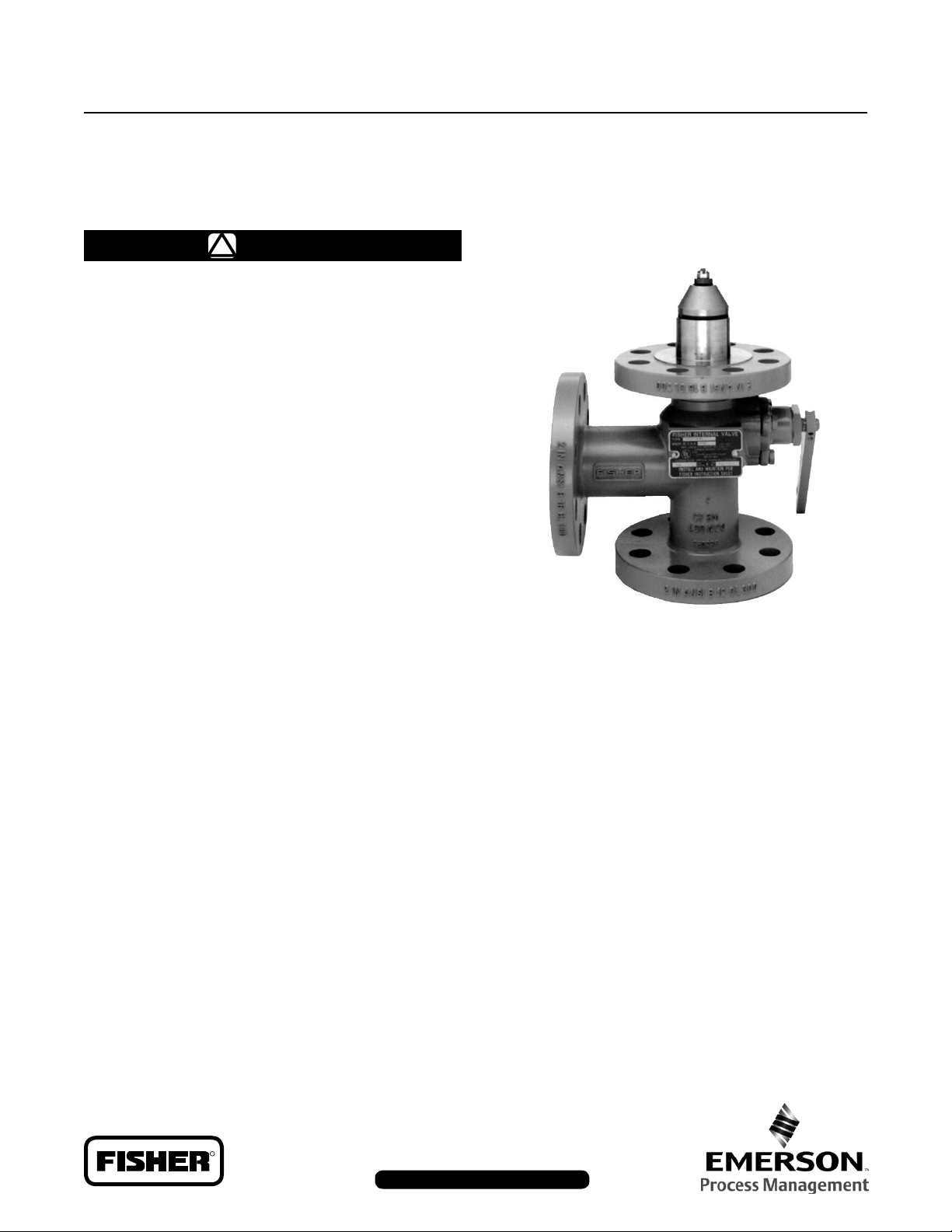
C831 Series Internal Valves
WARNING
!
Failure to follow these instructions or
to properly install and maintain this
equipment could result in an explosion,
re and/or chemical contamination
causing property damage and personal
injury or death.
Fisher equipment must be installed,
operated, and maintained in accordance
with federal, state, and local codes and
Fisher instructions.
Only personnel trained in the proper
procedures, codes, standards, and
regulations of the applicable industrial
service should install and service
this equipment.
C831 Series
The internal valve must be closed except
during product transfer. A line break
downstream of a pump may not actuate
the excess ow valve. If any break
occurs in the system or if the excess
ow valve closes, the system should be
shut down immediately.
Introduction
Scope of Manual
This manual covers instructions for the C831 Series 2
and 3-inch Class 300 Raised Face Flange internal valves.
These valves are serialized for the service specied with
the order. The valves can be used on other compressed
gases, but the user should check with the factory to
make sure the valve materials are suitable for the
intended service.
Description
The valves are typically used on the inlets and outlets of
transport trucks and on large stationary storage tanks.
Figure 1. C831 Series
Specications
The Specications table lists specications for C831 Series
internal valves.
DOT Internal Self-Closing Stop Valve Requirement
—U.S. Department of Transportation (DOT) regulations
49CFR§178.337-8(a)(4) require each liquid or vapor
discharge outlet on cargo tanks (except for cargo tanks used
to transport chlorine, carbon dioxide, refrigerated liquid, and
certain cargo tanks certied prior to January 1, 1995) to be
tted with an internal self-closing stop valve. Fisher’s “C”
series internal valves comply with the internal self-closing
stop valve requirement under the DOT regulations.
D450090T012
R
www.FISHERregulators.com/lp

C831 Series
Specications
Body Size and End Connection Style
Inlet: 2 or 3-inch
Class 300 ANSI Raised Face Flanged
Outlet: 2 or 3-inch
Class 300 ANSI Raised Face Flanged
Number of Outlets
C831 Series: 2 (side and straight through)
Maximum Allowable Inlet Pressure
500 psig (34,5 bar) WOG
Excess Flow Springs
2-Inch Size: 85, 110 and 160 GPM
(322, 416, 605 l/min) water
3-Inch Size: 110, 145,175, 270, and 345 GPM
(416, 549, 662, 1022, 1306 l/min) water
Temperature Capabilities
-20° to 150°F (-29° to 66°C)
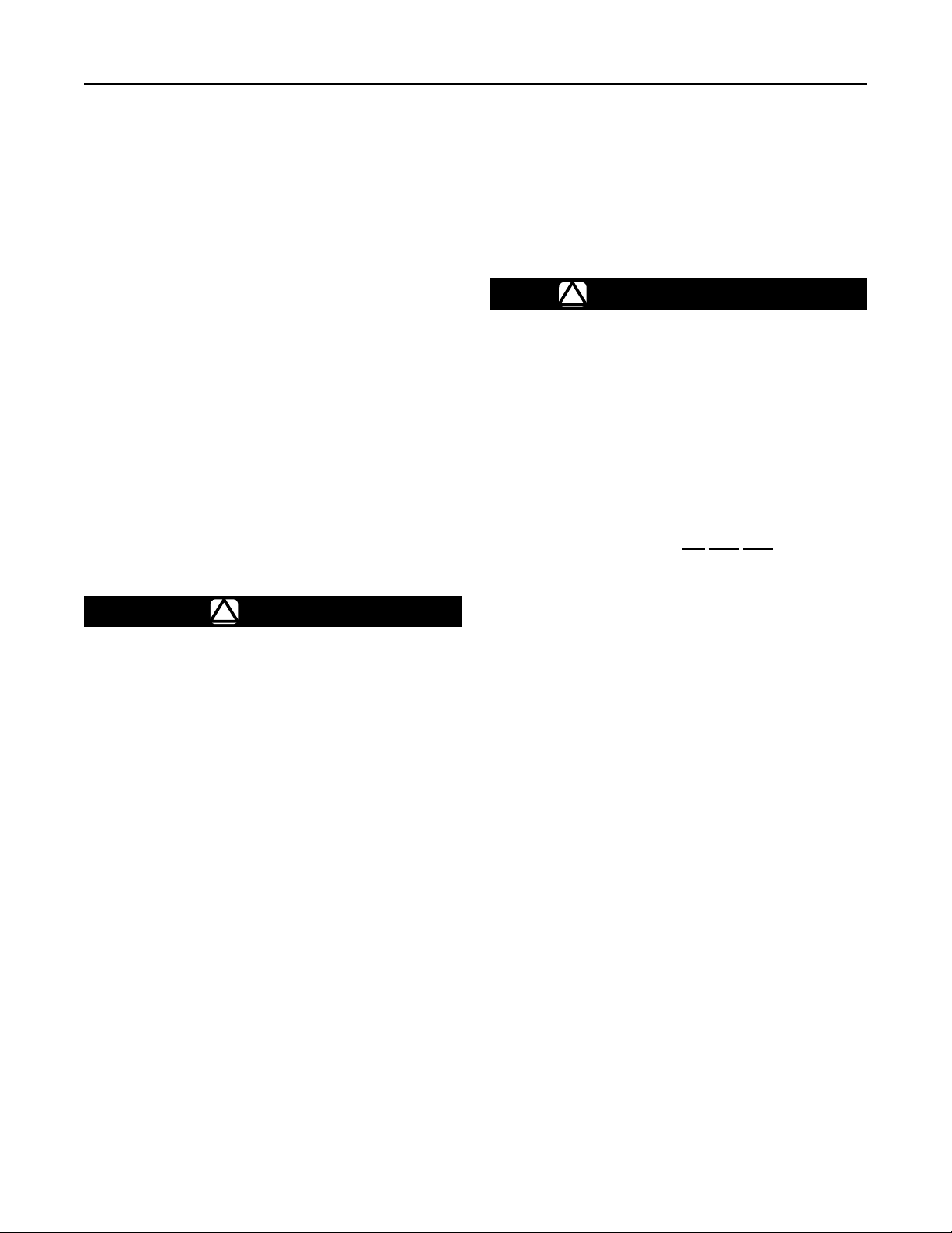
O.D AND THICKNESS TO SUIT CONTAINER
C
TANK CONNECTION FLANGES - DIMENSIONS ARE IN INCHES (mm)
300 LB
ANSI RF
FLANGE
2-inch
3-inch
A-BOLTING
DBC NO. Size
5.0
8
(127)
6.62
8
(168)
45°
SPECIFICATIONS
E
B
A
Figure 2
B RF C RF D E
5/8
3.62
(15,9)
(92)
3/4
5.75
(19,0)
(146)
D MAX
0.06
(1,5)
0.06
(1,5)
1.45
(36,8)
1.50
(38)
2.46
(62,5)
4.62
(117)
INCH (mm)
MATING
FLANGE O.D.
6.50 (165)
8.25 (210)
1 (25,4)
MINIMUM
3/4-IO UNC
Approximate Weight
2-Inch: 20 pounds (9 kg)
3-Inch: 32 pounds (14 kg)
Construction Materials
Stainless Steel: Lever, Cam, Disc Holder, Springs,
Hexagon Head Cap Screws, Cotter Pin, Stub Shaft,
Stem, Washers, Drive Screw, Plug Holder, Stop
Tube, Body, Gland, Web, Pins, Screws, Bolts, Nut
Washer, Spring Seat, Disc Retainer, Disc Holder,
and Retainer
Plated Steel: Nameplate, Drive Pin
Polyurethane: Rod Wiper
PTFE or Filled PTFE: Gland Packing, Liner Brushing,
Washer, Wear Plug
Nitrile (Standard Construction): Disc and O-Rings
Other Disc and O-Ring Trim Material Available
from Factory: TFE, Neoprene, Ethylene Propylene,
Viton, and Kalrez
Keep piping from the valve outlet to the pump full size and
as short as possible with a minimum number of bends.
Reduction in pipe size to suit smaller pump inlets should
be made as close to the pump as possible using forged
reducers (swage nipples) or venturi tapers rather than
bushings. This assures minimum ow resistance and
efcient pump operation.
The valves have a break off section below the inlet
ange which is intended to permit the lower valve body
to shear off in an accident, leaving the valve seat in the
tank. The break off section is designed for container
installations and will probably not provide shear
protection if the valve is installed in a pipeline.
A hydrostatic relief valve does not need to be installed
adjacent to the valve since the internal valve relieves
excessive line pressure into the tank.
Installation
Note
Installer must furnish 8 stud bolts,
8 ange nuts, and spiral wound gaskets
as these parts are not supplied with the
internal valves.
Coat both sides of the spiral wound gaskets with
Dow Corning #111 silicone grease or equivalent. An
appropriately sized tank ange, see Figure 2, must be
installed in the tank. The internal valve can then be
installed in the tank and outlet piping attached to the
internal valve.
2
Selectively Filling Manifolded Tanks
Fisher internal valves provide positive shutoff only in one
direction, from out of the tank to downstream of the valve.
The internal valves are designed to allow gas to ow into
a tank when the downstream line pressure exceeds tank
pressure. If you want to selectively ll one or more of the
other tanks in a tank manifold system, you must place a
positive shutoff valve downstream of the internal valve,
otherwise, all tanks will be lled at the same time and at
about the same rate.
C831 Series
Actuators
The remote operating control system for the valve is
extremely important, and it must be installed to conform
with the applicable codes. DOT MC331, for example,
most generally applies for trucks.
Fisher offers both cable controls and air cylinder
systems to operate the C831 Series internal valves. It
may also be possible to use cable controls from other
manufacturers or to fabricate a linkage mechanism.
Any control system requires thermal protection (fuse
links) at the valve, at the remote control point and, if
necessary, near the hose connections. The instruction
manuals for Fisher Controls actuator systems show how
to install the fuse links.
Installation instructions on Fisher Types P650, P163A,
and P164A cable controls, are in Form MCK-1083. Air
cylinder actuator installation is covered in Form
MCK-1137. Type P340 latch/remote release instructions
are on Form MCK-2048.
The operating linkage must allow the operating lever to
move from the fully closed position to within 2° of the fully
open position. The linkage should not apply strong force
to the lever past the fully open position or the valve could
be damaged.
CAUTION
The internal valve’s closing spring is
not designed to overcome drag in the
control linkage in order to close the valve.
Depending upon the control system
used, an external spring (such as Fisher
drawing number 1K4434) or positive
closing linkage may be needed. Be sure
the control system is installed to prevent
binding that could cause the valve to stick
in the open position.
Excess Flow Operation
Likewise, if the internal valve is installed on a stationary
tank or in the related downstream piping system, the
integral excess ow valve can provide protection against
an unintentional release of hazardous materials in the
event that a pump or piping attached directly to the
internal valve is sheared off before the rst valve, pump,
or tting downstream of the internal valve, provided that
the ow of product through the internal valve reaches the
rated ow specied by Fisher.
!
EXPLOSION HAZARD
Restrictions incorporated in the discharge
system of a bobtail truck or transport or of
a stationary tank (due to pumps, pipe and
hose length and dimensions, branching,
elbows, reductions in pipe diameter, or a
number of other in-line valves or ttings),
low operating pressure as a result of
ambient temperature, or a partially closed
valve downstream from the integral excess
ow valve, can restrict the rate of ow
through the internal valve below the level
necessary to actuate the integral excess
ow valve. Therefore, DO NOT USE the
excess ow function of the internal valve
for the purpose of providing protection
against the discharge of hazardous
materials in the event of a rupture of hose
or piping at a point in the discharge system
downstream from the rst valve, pump, or
tting downstream of the internal valve.
The internal valve is designed with an
internal bleed feature for equalization of
pressure. After the integral excess ow
valve closes, the leakage through the
bleed must be controlled or a hazard can
be created. For this reason the operator
must be familiar with the closure controls
for the internal valve and must close
the internal valve immediately after the
integral excess ow valve closes.
The internal valve contains an excess ow function, or
“integral excess ow valve”, that will close when the ow
exceeds the ow rating established by Fisher. Fisher’s
integral excess ow valve installed on a bobtail truck or
transport can provide protection against the discharge
of hazardous materials during an unloading operation of
a bobtail truck or transport in the event that a pump or
piping attached directly to the internal valve is sheared
off before the rst valve, pump, or tting downstream of
the internal valve, provided that the cargo tank pressure
produces a ow rate greater than the valve’s excess
ow rating.
Failure to follow this warning could result in
serious personal injury or property damage
from a re or explosion.
DOT Passive Shutdown Equipment Requirement
—DOT regulations 49CFR§173.315(n)(2) require certain
cargo tanks transporting propane, anhydrous ammonia
and other liqueed compressed gases to be equipped
with passive emergency discharge control equipment
that will automatically shut off the ow of product without
human intervention within 20 seconds of an unintentional
release caused by complete separation of a delivery
hose. The design for each passive shutdown system
3
 Loading...