

Installation Guide
D103077X014
English - November 2017
EZH and EZHSO Series
Introduction
This installation guide provides instructions for installation,
startup, and adjustment. To receive a copy of the Instruction
Manual, contact your local Sales Office or view a copy at
www.fisher.com. For further information refer to: EZH and
EZHSO Series Pressure Reducing Regulators Instruction
Manual, D103077X012.
P.E.D. Categories
This product may be used as a pressure accessory with
pressure equipment in the following Pressure Equipment
Directive categories. It may also be used outside of the
Pressure Equipment Directive using sound engineering practice
(SEP) per table below. For information on the current PED
revision see Bulletin: D103053X012
TYPE PRODUCT SIZE
EZH
EZHSO
EZHOSX
EZHSO-OSX
DN 25, 50, 80 and 100 /
NPS 1, 2, 3 and 4
DN 25, 50 and 80 /
NPS 1, 2 and 3
DN 25, 50, 80 and 100 /
NPS 1, 2, 3 and 4
DN 25, 50 and 80 /
NPS 1, 2 and 3
Specifications
Available Configurations
Type EZH (Spring-to-Close): Pilot-operated pressure
reducing regulator for low to high outlet pressure
Type EZHSO (Spring-to-Open): Pilot-operated
BODY
MATERIAL
WCC Steel IV
WCC Steel IV
LCC Steel IV
LCC Steel IV
CATEGORY
Minimum Differential Pressures
MAIN VALVE
SERIES
EZH
EZHSO
BODY SIZE
DN NPS bar d psid bar d psid
25 1 1.1 15.2 1.1 15.7
50 2 0.83 12.0 0.95 13.8
80 3 0.73 10.6 0.88 12.8
100 4 1.1 15.8 1.1 16.4
150, 200,
300 X 150
25 1
80 3
100 4 - - - - - - - - 1.8 25.6
150, 200,
300 X 150
Pressure Registration
External
Pilot Connections
1/4 NPT
Temperature Capabilities
Nitrile (NBR) Version:
-29 to 82ºC / -20 to 180ºF
Fluorocarbon (FKM) Version:
-18 to 82ºC / 0 to 180ºF
Polyurethane (PU) Version:
DN 25, 50, 150, 200 and 300 X 150 / NPS 1, 2, 6, 8 and
12 X 6 Sizes:
-30 to 82°C / -22 to 180°F
DN 80 to 100 / NPS 3 to 4 Sizes:
-20 to 82°C / -4 to 180°F
pressure reducing regulator for low to high
outlet pressure
Type EZHOSX: Type EZH with a Type OS2 slam-shut
Installation
device for overpressure (OPSO) or overpressure and
underpressure (OPSO/UPSO) protection
Type EZHSO-OSX: Type EZHSO with a Type OS2
slam-shut device for overpressure (OPSO)
or overpressure and underpressure (OPSO/
UPSO) protection
Body Sizes, End Connection Styles and
Pressure Ratings
(1)
See Table 1
Maximum Inlet and Outlet (Casing) Pressures
(1)
103 bar / 1500 psig
Maximum Emergency (Design Casing Pressure)
103 bar / 1500 psig
Maximum Operating Differential Pressure
(1)(4)
Main Valve: 103 bar d / 1500 psid
Pilot: Between loading pressure in pilot and loading
sense pressure: 85.0 bar d / 1233 psid
Outlet Pressure
(1)
Only qualified personnel shall install or
service a regulator. Regulators should
be installed, operated and maintained in
accordance with international and applicable
codes and regulations and Emerson Process
Management Regulator Technologies,
Inc. instructions.
If the regulator vents fluid or a leak develops
in the system, it indicates that service
is required. Failure to take the regulator
out of service immediately may create a
hazardous condition.
Personal injury, equipment damage or
leakage due to escaping fluid or bursting of
pressure containing parts may result if this
regulator is overpressured or is installed
where service conditions could exceed the
See Table 2
1. The pressure/temperature limits in this Installation Guide and any applicable standard or code limitation should not be exceeded.
2. When using a Type SA/2 pilot supply lter regulator, the differential pressure across the regulator must be a least 3.1 bar d / 45 psid
for optimum regulator performance.
3. Types PRX and SA/2 Fluorocarbon (FKM) elastomer is limited to -18°C / 0°F.
4. Maximum Operating Differential Pressure is 96.5 bar d / 1400 psid for DN 25 / NPS 1 EZHSO Series.
6, 8,
12 X 6
6, 8,
12 X 6
WARNING
!
(1)(2)
MINIMUM DIFFERENTIAL
For 90% Capacity For 100% Capacity
- - - - - - - - 0.97 14.0
3.8 55 3.8 5550 2
- - - - - - - - 0.97 14.0
(1)
(3)

EZH and EZHSO Series
Table 1. Main Valve Body Sizes, End Connection Styles and Body Ratings
MAIN VALVE BODY SIZE
DN NPS bar psig
25 and 50 1 and 2
25, 50, 80, 100,
150, 300 X 150
and 200
1, 2, 3, 4, 6,
12 X 6 and 8
MAIN VALVE BODY MATERIAL END CONNECTION STYLE
NPT or SWE 103 1500
CL150 RF 20.0 290
LCC or WCC Steel
CL300 RF 51.7 750
CL600 RF or BWE 103 1500
Table 2. Outlet Pressure Ranges
TYPE
PRX/120
PRX/125
PRX/120-AP
PRX/125-AP
OUTLET PRESSURE RANGE AC (ACCURACY CLASS) PILOT CONTROL SPRING INFORMATION
bar psig EZH Series EZHSO Series Spring Color Part Number
1.00 to 1.8
1.6 to 3.0
2.8 to 5.5
5.0 to 8.5
8.0 to 14.5
14.0 to 23.0
22.0 to 30.0
30.0 to 80.0 435 to 1160 1% 2.5% Clear M0273790X12
14.5 to 26
23 to 44
41 to 80
73 to 123
116 to 210
203 to 334
319 to 435
2.5% 2.5%
1% 2.5%
STRUCTURAL DESIGN RATING
Yellow
Green
Blue
Black
Silver
Gold
Aluminum
M0255240X12
M0255230X12
M0255180X12
M0255220X12
M0255210X12
M0255200X12
M0255860X12
limits given in the Specifications section or
where conditions exceed any ratings of the
adjacent piping or piping connections.
To avoid such injury or damage, provide
pressure-relieving or pressure-limiting
devices (as required by the appropriate code,
regulation or standard) to prevent service
conditions from exceeding limits.
Additionally, physical damage to the regulator
could result in personal injury and property
damage due to escaping fluid. To avoid such
injury and damage, install the regulator in a
safe location.
Clean out all pipelines before installation of the regulator
and check to be sure the regulator has not been damaged
or has collected foreign material during shipping. For NPT
bodies, apply pipe compound to the external pipe threads.
For flanged bodies, use suitable line gaskets and approved
piping and bolting practices. Install the regulator in any
position desired, unless otherwise specified, but be sure flow
through the body is in the direction indicated by the arrow on
the body.
Note
It is important that the regulator be installed
so that the vent hole in the spring case
is unobstructed at all times. For outdoor
installations, the regulator should be
located away from vehicular traffic and
positioned so that water, ice and other
foreign materials cannot enter the spring
case through the vent. Avoid placing the
regulator beneath eaves or downspouts and
be sure it is above the probable snow level.
Overpressure Protection
The recommended pressure limitations are stamped on
the regulator nameplate. Some type of overpressure
protection is needed if the actual inlet pressure exceeds the
maximum operating outlet pressure rating. Overpressure
protection should also be provided if the regulator inlet
pressure is greater than the safe working pressure of the
downstream equipment.
Regulator operation below the maximum pressure limitations
does not preclude the possibility of damage from external
sources or debris in the line. The regulator should be
inspected for damage after any overpressure condition.
Startup
The regulator is factory set at approximately the midpoint
of the spring range or the pressure requested, so an initial
adjustment may be required to give the desired results.
With proper installation completed and relief valves properly
adjusted, slowly open the upstream and downstream
shutoff valves.
Adjustment
The adjustment of setpoint is performed using the pilot
adjusting screw. To change the outlet pressure, loosen the
jam nut and turn the adjusting screw clockwise to increase
outlet pressure or counterclockwise to decrease it. Monitor
the outlet pressure with a test gauge during the adjustment.
Tighten the jam nut to maintain the desired setting.
Taking Out of Service (Shutdown)
WARNING
!
To avoid personal injury resulting from
sudden release of pressure, isolate
the regulator from all pressure before
attempting disassembly.
2

EZH and EZHSO Series
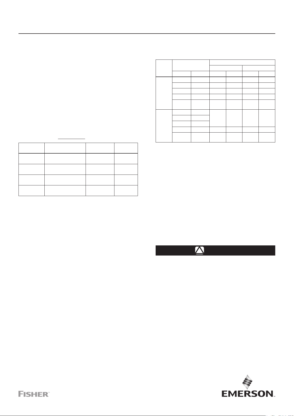
Parts List
EZH and EZHSO Series Main Valve
(Figures 1 and 2)
Key Description
1 Body
2 Seat Ring
(1)
3
Cage
4* Anti-Friction Ring
5 Actuator Lower Casing
6 Cap Screws
7* O-ring
8* Anti-Friction Rings
9* O-ring
10 Pipe Plug
11 Actuator Upper Casing
13 Spring
14 Sleeve
15* O-ring
16 Socket Head Cap Screw
17* O-ring
18 Inlet Plate
19 Outlet Plate
20* Diaphragm
21 Cap Screw
22 Plain Washer
23 Hex Nut
24 Continuous Thread
Stud Bolt
25 Intermediate Flange
26 Hex Nut
27 Sleeve Adaptor
28* O-ring
29* O-ring
30* Disk Holder Assembly
31 Disk Retainer
32 Lock Washer
33 Socket Head Cap Screw
EZH Series only
34* O-ring
35 Bracket or Eyebolt
36 Nameplate
37 Drive Screw
38 Travel Indicator Plug
39 Long Bolt
43 Caution/Warning Label
44 Adjusting Screw Cap
59 Flow Arrow
60 Protective Cap
61 Sleeve Guide
62* O-ring
Mounting Parts (Figures 3 through 4)
Standard Configurations for Single Pilot and Working
Monitor Pilots
Key Description
46 Pipe Nipple
Pre-Piped Pilot Supply Single-Pilot Configuration
(with standard body or tapped inlet body)
Key Description
47 Pipe Nipple
48 Tube Elbow (4 required)
49 External Tube Connector
Key Description
63* O-ring
64* O-ring
66 Socket Head Set Screw
67 Crush Washer
68 Special Screw
69* O-ring
70 Cap
71* O-ring
72 Locking Nut
EZH Series
73 Upper Spring Seat
74 Hex Socket Cap Screw
75* O-ring
77 Screw
82 Lower Spring Seat
83 Ball Bearing
138 Travel Indicator Cover
139 Travel Indicator Stem
140 Indicator Bushing
141 Travel Indicator Fitting
142A* O-ring
142B* O-ring
143* O-ring
144 Spring Collet
145 Retaining Ring
146 Protective Cap
147 Stem
148 Upper Spring Seat
149 Lower Spring Seat
150 Ring Guide
151 Stem Nut
152 Hex Nut
153 O-ring
154 Hex Socket Cap Screw
155 Stem Nut
156 Upper Spring Seat Adapter
157 Anti-friction ring
158 O-ring
159 Check valve
160* Back-up ring
192 Travel Indicator Scale
193 Washer
195 Pipe Plug
196 Washer
197 Seat Adaptor
198 O-ring
Key Description
47 Pipe Nipple
Key Description
51 Pipe Cross
52 Tubing
Pre-Piped Pilot Supply and Pilot Exhaust
Single-Pilot Configuration
(with tapped inlet and outlet body)
Key Description
47 Pipe Nipple
48 Tube Elbow (5 required)
49 External Tube Connector
50 Pipe Tee
Key Description
51 Pipe Cross
52 Tubing
55 Internal Connector
Pre-Piped Pilot Supply Working Monitor
Pilot Configuration
(with standard body or tapped inlet body)
Key Description
47 Pipe Nipple
48 Tube Elbow
49 External Tube Connector
50 Pipe Tee
Key Description
51 Pipe Cross
52 Tubing
54 Pipe Nipple
Pre-Piped Pilot Supply and Pilot Exhaust Working
Monitor Pilot Configuration
(with tapped inlet and outlet body)
Key Description
47 Pipe Nipple (2 required)
48 Tube Elbow (5 required)
49 External Tube Connector
(2 required)
50 Pipe Tee
Key Description
51 Pipe Cross
52 Tubing
53 90° NPT Pipe Elbow
54 Pipe Nipple
55 Internal Connector
PRX Series Pilots (Figure 5)
Key Description
1 Adjusting Screw
2 Locknut
3 Cap
4* Upper Cover O-ring
5* O-ring
6 Upper Spring Seat
7 Spring
8 Upper Cover
9 Lower Spring Seat
10 Machine Screw
11 Washer
12 Filter
13 Upper Diaphragm Plate
14* Diaphragm
15 Lower Diaphragm Plate
16 Body
17* Orice O-ring
18* Lower Cover O-ring
19 Orice
20 Nut
Key Description
21 Lower Cover
22* Pad Holder
23 Stem
24 Nameplate
25* Stem O-ring
26 Upper Diaphragm Nut
27 Damper Adjusting Screw
with Hole
28* Restrictor/Damper O-ring
29 Damper/Restrictor Plate
30 Ring Nut
31 Nameplate Screw
32 Restrictor Adjusting Screw
with Hole
33 Plug (Types PRX/125 and
PRX/125-AP only)
34 Plug (Types PRX/125 and
PRX/125-AP only)
35 Spring Barrel Extension
for AP
Type SA/2 Pilot Supply Filter Regulators
(Figure 6)
Key Description
1 Spring
2 Socket Head Cap Screw
3 Washer
4 Plate
5 Regulator Seat
6* O-ring
7 Body
8 Filter Net
9 Washer
10 Nut
11 Filter Cover
Key Description
12* Felt
13* O-ring
14 Spring
15* Pad Holder Unit
16 Nameplate
17 Screw Unit
18* Diaphragm
19 Regulator Cover
20 Spring Washer
21 Nut
*Recommended spare part
1. When retrotting an EZH Series with pins with the new cage, it is also necessary to order the Seat Ring.
3
EZH and EZHSO Series
L2
L2
L2
L2
L2
L2
15
16 171819
L2
L1
20
10
21
22
23
24
25
26
6
S1
27
L2
28
29
L2
30
31
32
33
S1
L2
34
32
33
S1
L2
L2 L2 L2
L2
L1
4810 9 8
44
11
10
62
8
9
8
7
5
4
3
2
1
13 14
TOP VIEW
L2
140
160
143
IMPROVED TRAVEL
INDICATOR DETAIL
138
139
140
141
142B
145
144
S2
L2
L2
143
VERSION WITHOUT
TRAVEL INDICATOR
DETAIL
DN 25 THROUGH 80 / NPS 1 THROUGH 3
GD89918_H
APPLY LUBRICANT (L) / SEALANT (S)
L1 = LITHIUM HYDROXYSTEGRATE NLGI 2 GRADE GREASE
L2 = SILICONE-BASED OR PTFE-BASED GREASE
S1 = ANAEROBIC METHACRYLATE SEALANT FOR NUTS AND BOLTS
S2 = ANAEROBIC METHACRYLATE SEALANT FOR THREADS
1. Lubricant and sealant must be selected such that they meet the temperature requirements.
(1)
:
38
35
6
FOR DN 25 / NPS 1
EZH SERIES
VERSION ONLY
FOR DN 80 / NPS 3
EZH SERIES
VERSION ONLY
Figure 1. EZH Series Main Valve Assembly
4
DN 25 THROUGH 80 / NPS 1 THROUGH 3
EZH and EZHSO Series
36
37
GD89918_J
43
60
35
39
37
59
43
37
36
37
59
MLM1945_B
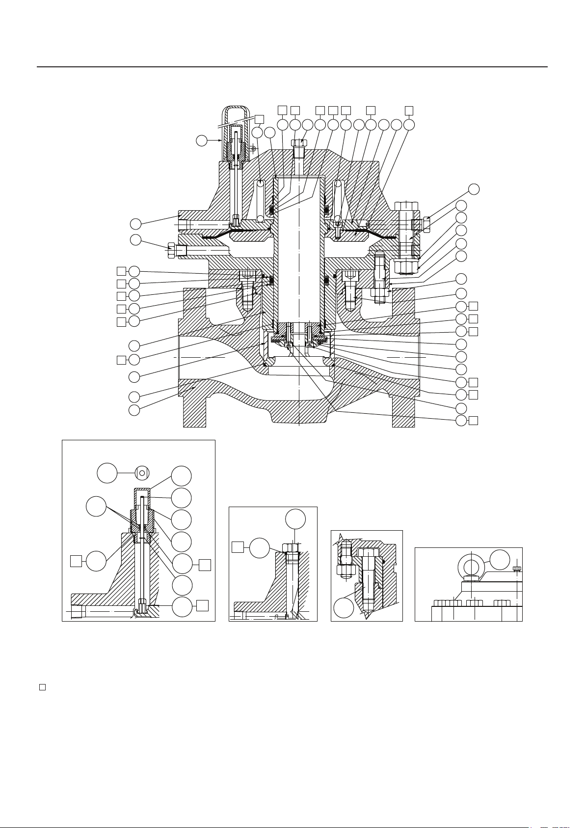
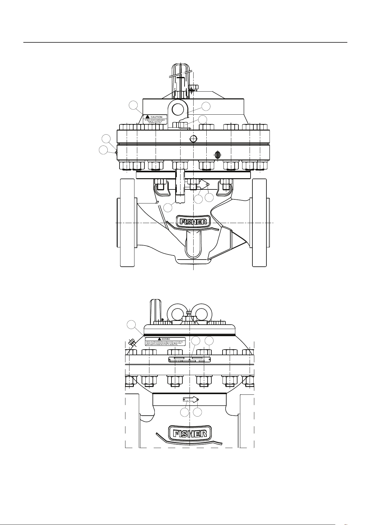
DN 100, 150, 200 AND 300 X 150 / NPS 4, 6, 8 AND 12 X 6
Figure 1. EZH Series Main Valve Assembly (continued)
5
 Loading...