

Fisher IM Supplement: HART Communicating FIELDVUE DVC6200 Digital Valve Controllers-Zero Point Calibration Manuals & Guides

Instruction Manual Supplement
D104328X012
Zero Point Calibration
DVC6200 Digital Valve Controller
June 2018
HART
®
Communicating Fisher™ FIELDVUE
™
DVC6200 Digital Valve Controllers
The Zero Point Calibration procedure allows you replace an existing DVC6200 digital valve controller without
performing a travel calibration. This procedure can be used when a situation occurs that requires the partial or
complete replacement of a digital valve controller when part of a valve assembly that does not have a process bypass
or the process cannot be shut down.
WARNING
Personal injury or property damage, caused by unexpected valve movement and an uncontrolled process, could result if
this procedure is attempted when the valve is not locked at its present position. If you cannot safely lock the valve in
position until this procedure is complete, do not proceed with this procedure.
Notes
This procedure should only used for the partial or complete replacement of a digital valve controller when the valve does not have
a bypass or the process cannot be shut down. Do not proceed with this procedure if the valve has a bypass or the process can be
shut down.
This procedure assumes the array was set up properly on the existing DVC6200 and has not been moved or adjusted since setup.
The valve will need to be locked at its present position. This can be accomplished by using a handwheel or other mechanism. If you
cannot safely lock the valve in position until this procedure is complete, do not proceed with this procedure.
™
This procedure requires the use of a 475 Field Communicator, AMS Trex
This procedure can be used to swap a DVC6200 with another DVC6200. You cannot swap a DVC6000 with a DVC6200 using this
procedure. The DVC6200 used to replace the existing digital valve controller must be a new, factory calibrated instrument. This
procedure will not work if a previously installed and calibrated digital valve controller is used.
Device Communicator, or ValveLink™ software.
Zero Point Configuration Process
HART DD
CAUTION
The touch screen of the 475 Field Communicator or AMS Trex Device Communicator should only be contacted by blunt
items. The use of a sharp instrument can cause damage to the touch screen interface.
www.Fisher.com

DVC6200 Digital Valve Controller
June 2018
Instruction Manual Supplement
475 Field Communicator and AMS Trex Device Communicator
1. If using the 475 Field Communicator, Select the HART Icon from the Main Menu, shown in figure 1.
If using the Trex Communicator, select Field Communicator from the main menu.
Figure 1. 475 Field Communicator Menu Screen
D104328X012
2. From the Online menu select Configure > Guided Setup > Device Setup.
3. Provide the requested information, including: Pressure Units, Relay Type, Control mode (Travel Control, Pressure
Control, Fallback-Sensor Failure, Fallback-Sensor/Tvl Deviation), max supply pressure, Actuator manufacturer,
Actuator model, Actuator size, Volume Booster/Quick Release.
4. Send the configuration to the instrument.
5. Use factory defaults for setup
6. Select Cancel (475) or Abort (Trex) when prompted to run Auto Tvl Calib.
7. Place the instrument “In Service”.
ValveLink Mobile
AMS Trex Device Communicator or 475 Field Communicator
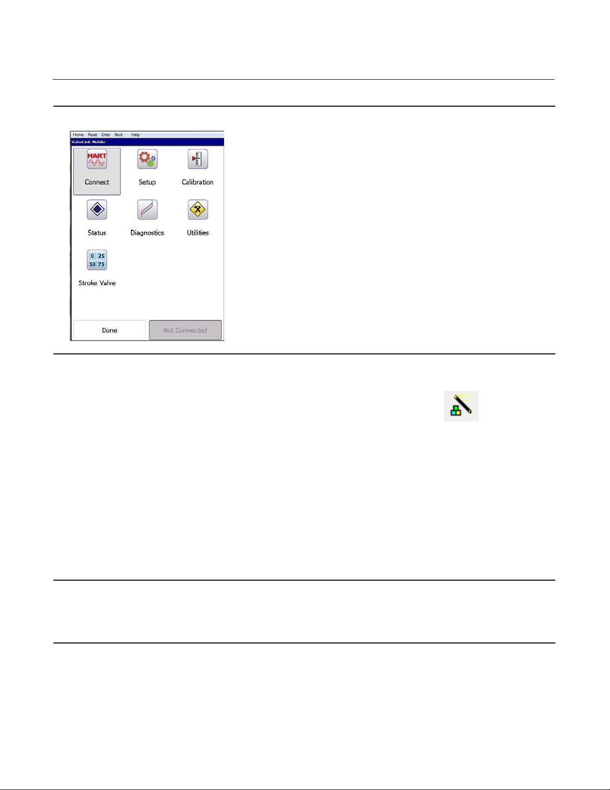
1. Select ValveLink Mobile from the Field Communicator Main Menu (see figure 1).
2. Select HART device.
3. Select Connect from the ValveLink Mobile main menu (see figure 2) to connect to the instrument.
4. Select Setup > Setup Wizard.
5. Provide the requested information then select Apply.
6. When prompted to run an Auto Travel Calibration select No.
7. Place the instrument “In Service”.
2
Instruction Manual Supplement
D104328X012
Figure 2. ValveLink Mobile Menu Screen
DVC6200 Digital Valve Controller
June 2018
ValveLink software
1. Initiate the Setup Wizard either from the Instrument Setup menu or Setup Wizard Icon .
2. Select the appropriate Travel/Pressure Control Mode and the Relay Type.
3. Set the desired Pressure Units and the Max Supply Pressure for the application.
4. Select the required Actuator Information including: Actuator Make, Actuator Model, Actuator Size, and designate if
a Volume Booster or Quick Exhaust Valve is present.
5. Select Yes when prompted to Use Factory Default Settings.
6. When prompted to run an Auto Travel Calibration select No.
7. Place the instrument “In Service”.
Alignment Verification
Note
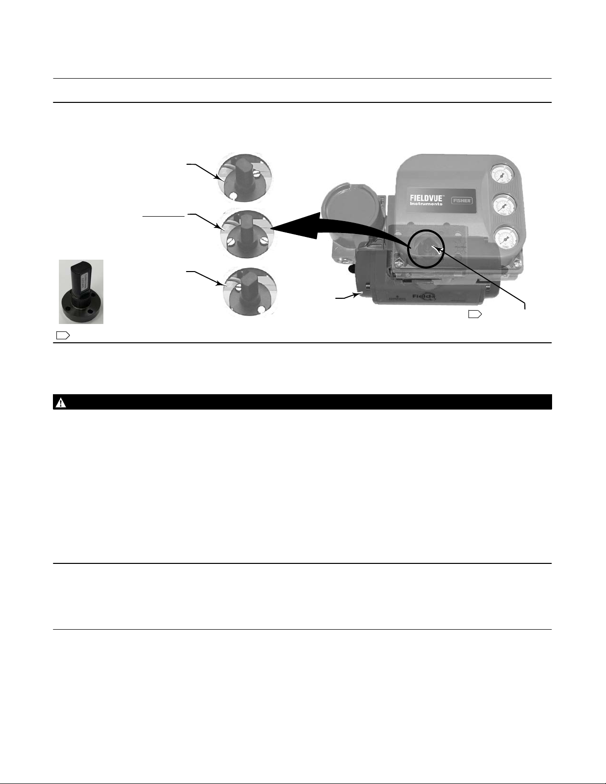
The rotary end mount array is the only array that must be verified. If the array is not at mid-travel, remove and reposition prior to
mounting the DVC6200.
All other arrays can be mounting in any direction, as they are not affected by north south polarity.
Alignment of the rotary array can impact the ability of the DVC6200 digital valve controller to properly follow the
setpoint. To ensure proper operation, the array must be mounted to the actuator with the label facing the gauge side
of the positioner when the valve is at 50% (mid) travel, see figure 3 below. If the array position is different, the array
should be removed and reoriented prior to mounting the DVC6200.
3
DVC6200 Digital Valve Controller
June 2018
Figure 3. Rotary Array Orientation
ORIENTATION
AT ONE TRAVEL
EXTREME
ORIENTATION
AT MID‐TRAVEL
(FLATS PARALLEL
TO DVC6200
CHANNEL)
ORIENTATION
AT THE OTHER
TRAVEL EXTREME
1 ROTARY ARRAY WITH STICKER SHOWN
ACTUATOR
Instruction Manual Supplement
D104328X012
DVC6200
W9700
STICKER WILL BE
1
ON GAUGE SIDE
To change a DVC6200 on the valve
WARNING
Avoid personal injury or property damage from sudden release of process pressure or bursting of parts. Before proceeding
with any Installation procedures:
D Always wear protective clothing, gloves, and eyewear to prevent personal injury or property damage.
D Do not remove or uncouple the actuator from the valve while the valve is still pressurized.
D The valve will need to be locked at its present position. If you cannot safely lock the valve in position until this procedure
is complete, do not proceed with this procedure.
D After the valve has been safely locked in position, disconnect any operating lines providing air pressure, electric power,
or a control signal to the actuator. Be sure the actuator cannot suddenly open or close the valve.
D Use lock‐out procedures to be sure that the above measures stay in effect while you work on the equipment.
D Check with your process or safety engineer for any additional measures that must be taken to protect against process
media.
Note
The lack of a travel calibration can impact the accuracy of the position feedback. While this does not impact the positioner’s ability
to control the process, it can influence the results of specific diagnostic tests. These tests include: Valve Signature, Dynamic Error
Band, and Step Response.
Block the valve into position either with a handwheel, with a pneumatic bypass arrangement that includes a regulator
and pressure gauge, or by mechanicallylocking the valve. Remove the existing digital valve controller by disconnecting
mounting hardware, being careful NOT to loosen or move the magnetic array that is connected to the valve stem
block. The magnetic array will remain on the valve and its position must remain the same. Install the new DVC6200
over the existing array assembly.
4
Instruction Manual Supplement
D104328X012
DVC6200 Digital Valve Controller
June 2018
WARNING
Personal injury or property damage, caused by unexpected valve movement, could result if the digital valve controller is
put in service with the connector arm or array moved from its original position.
If the connector arm or array is moved, the digital valve controller must be calibrated before putting it in service. Refer to
the appropriate instruction manual or quick start guide for calibration information.
Ensure that air and signal is supplied to the digital valve controller and remove mechanism for locking the valve in
place. Allow for a slow transition from manual to auto loop control.
Note
For a DVC6200 on a DeltaV system go to Detailed Setup to ensure the input units are set to 0 - 100%.
Note
To ensure greater accuracy, perform an auto travel calibration on the digital valve controller when conditions allow.
Related Documents
D Fisher FIELDVUE DVC6200 Series Digital Valve Controller Quick Start Guide (D103566X012)
D Fisher FIELDVUE DVC6200 HW2 Digital Valve Controller Instruction Manual (D103605X012
D Fisher FIELDVUE DVC6200 HW1 Digital Valve Controller Instruction Manual (Supported) (D103409X012
These documents are available from your Emerson sales office
Neither Emerson, Emerson Automation Solutions, nor any of their affiliated entities assumes responsibility for the selection, use or maintenance
of any product. Responsibility for proper selection, use, and maintenance of any product remains solely with the purchaser and end user.
Fisher, FIELDVUE, ValveLink, and Trex are marks owned by one of the companies in the Emerson Automation Solutions business unit of Emerson Electric Co.
Emerson Automation Solutions, Emerson, and the Emerson logo are trademarks and service marks of Emerson Electric Co. All other marks are the property
of their respective owners.
The contents of this publication are presented for informational purposes only, and while every effort has been made to ensure their accuracy, they are not
to be construed as warranties or guarantees, express or implied, regarding the products or services described herein or their use or applicability. All sales are
governed by our terms and conditions, which are available upon request. We reserve the right to modify or improve the designs or specifications of such
products at any time without notice.
Emerson Automation Solutions
Marshalltown, Iowa 50158 USA
Sorocaba, 18087 Brazil
Cernay, 68700 France
Dubai, United Arab Emirates
Singapore 128461 Singapore
www.Fisher.com
or Local Business Partner, or at www.Fisher.com.
)
)
E 2017, 2018 Fisher Controls International LLC. All rights reserved.
5
 Loading...