

Fisher IM Supplement: Fisher DLC3100 Digital Level Controller - ATEX and IECEx Approvals Manuals & Guides

Quick Start Guide Supplement
D104233X012
DLC3100 Digital Valve Controller
ATEX and IECEx Hazardous Area Approvals
October 2020
Fisher
™
FIELDVUE™ DLC3100 Digital Level
Controller
Hazardous Area Classifications and Special Instructions for “Safe
Use” and Installations in Hazardous Locations
Certain nameplates may carry more than one approval, and each approval may have unique installation/wiring
requirements and/or conditions of “safe use”. These special instructions for “safe use” are in addition to, and may
override, the standard installation procedures. Special instructions are listed by approval.
Note
This information supplements the nameplate markings affixed to the product and the DLC3100 quick start guide (D104214X012),
available from your Emerson sales office
Always refer to the nameplate itself to identify the appropriate certification.
WARNING
Failure to follow these conditions of “safe use” could result in personal injury or property damage from fire or explosion, or
area re‐classification.
or Fisher.com.
1. Two 1/2-14 NPT entries available for conduit connection.
2. Cable gland must be Ex certified in accordance with the intended use of the apparatus (Ex db or Ex tb)
3. Blanking elements shall be used if an entry to this apparatus is not used. The blanking element must be Ex certified
in accordance with the intended use of the apparatus (Ex db or Ex tb).
4. Thread adapters must be Ex certified in accordance with the intended use of the apparatus (Ex db or Ex tb).
5. A thread adapter cannot be used with an Ex db blanking element.
6. Only one thread adaptor can be used with an Ex db cable gland.
7. Manufacturer must be contacted for any repairs involving flameproof joints.
8. Coating instrument with paint or powder-coat finish is not permitted.
9. Lubribond 320 must be used as lubricant when needed to maintain the terminal box flameproof joint.
10. In Ex tb applications, the front cover shall not be removed to gain access to the field wiring connections or
in-service adjusting facilities.
11. Temperature at wiring entry point may exceed 80°C, appropriate conductors and adaptors for this temperature
must be used. For Ex nA and Ex tc, see Specific Conditions of Use below.
2
12. External terminal ground cabling must be 4 mm
13. 16-26 AWG size is recommended for installation per terminal block supplier.
www.Fisher.com
minimum for ATEX and IECEx.
DLC3100 Digital Valve Controller
October 2020
Quick Start Guide Supplement
D104233X012
Specific Conditions Of Use
For Ex ia Ga + Ex ia Da
1. Repairs of flameproof joints should not be undertaken by the end user. In the event that a flameproof joint must be
repaired, contact the manufacturer.
2. The special fasteners can be replaced only by the identical fasteners - contact the manufacturer.
For Ex db + Ex tb
3. The equipment should be equipped with suitably certified entry accessories with a compatible mode of protection
for the intended use.
4. At Tamb
Table 1. Approval Information, ATEX
Certificate Approval Standards Applied Certification Obtained
ATEX
≤ 75°C, the cable used shall have an operating temperature greater than 80°C.
EU Directive 2014/34/EU
Flameproof and Dust
Intrinsic Safety and Dust
EN 60079-0:2012 + A11:2013
EN 60079-1:2014
EN 60079-31:2014
EU Directive 2014/34/EU
EN 60079-0:2012 + A11:2013
EN 60079-11:2012
Ex db IIC T5(Ta≤75°C)/T6(Ta≤55°C) Gb
Ex tb IIIC T78°C Db
Ex ia IIC T5(Tamb ≤ 80°C)/T6(Tamb ≤ 55°C) Ga
Ex ia IIIC T100°C(Tamb ≤ 80°C)/T85(Tamb ≤ 55°C) Da
Per Drawing GG57089 (see figure 3)
Table 2. Approval Information, IECEx
Certificate Approval Standards Applied Certification Obtained
Flameproof and Dust
IECEx
Intrinsic Safety and Dust
IEC 60079-0:2011
IEC 60079-1:2014
IEC 60079-31:2013
IEC 60079-0:2011
IEC 60079-11:2011
Ex db IIC Gb T5(Ta≤75°C)/T6(Ta≤55°C)
Ex tb IIIC Db T78°C
Ex ia IIC T5(Tamb ≤ 80°C)/T6(Tamb ≤ 55°C) Ga
Ex ia IIIC T100°C(Tamb ≤ 80°C)/T85(Tamb ≤ 55°C) Da
Per Drawing GG57089 (see figure 3)
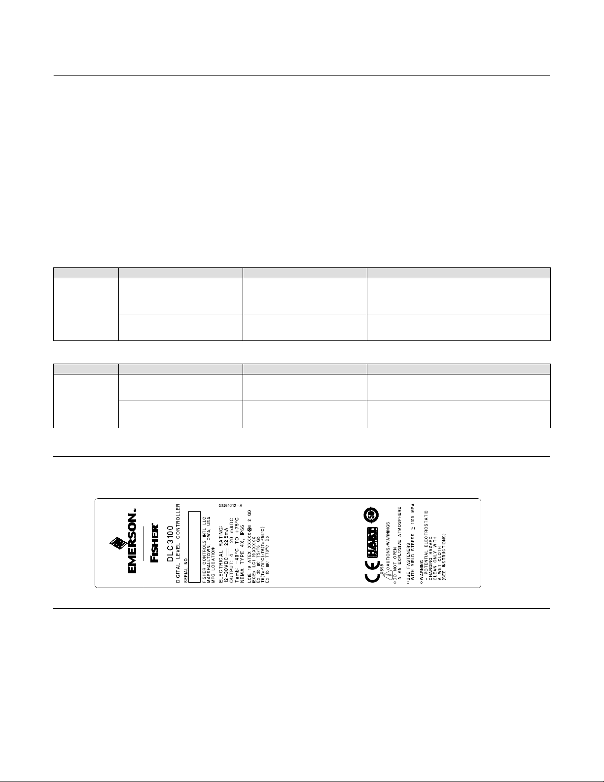
Figure 1. DLC3100—ATEX/IECEx Flameproof and Dust Nameplate
2
 Loading...