

Fisher IM Supplement: FIELDVUE DVC6200 Digital Valve Controller HART Field Device Specification Manuals & Guides
Instruction Manual Supplement
D103639X012
HART® Field Device Specification
DVC6200 Digital Valve Controller
September 2019
Fisher
™
FIELDVUE™ DVC6200 Digital Valve
Controller
HART Revision Device Type Device Revision Firmware Revision
HART 5 09 1 3, 4, 5, 6, 7
HART 7 1309
Contents
Introduction 2.................................
Product Overview 2............................
Purpose of this document 2.....................
Abbreviations and definitions 2..................
Reference Documentation 3....................
Device Identification 3..........................
Product Interfaces 4............................
Control Valve Interface 4.......................
Host interface 4...............................
Pushbutton Calibration 4.......................
Internal Jumpers and Switches 5.................
Write Protection 5.............................
Dynamic Variables 6............................
Device Variables 6..............................
Unit Codes 7...................................
Status Information 7............................
Device Status 7...............................
Universal Commands 8..........................
CommonPractice Commands 16.................
Burst Mode 16................................
Condensed Status 16..........................
Device-Specific Commands 22....................
Performance 22................................
Annex A Compatibility Checklist 23................
Annex B DVC6200 Parameters as part of a
Rosemount
Gateway 24...............................
™
1410/1420 WirelessHART
®
2 3, 4, 5, 6
3 7
W9713
www.Fisher.com

DVC6200 Digital Valve Controller
September 2019
Instruction Manual Supplement
D103639X012
Introduction
Product Overview
The FIELDVUE DVC6200 digital valve controller is designed to control the pneumatic actuator of a process control
valve. It receives a current signal from a host and uses instrument air supply to create a metered pressure output signal
to the pneumatic actuator. Movement of the actuator as it positions the process control valve is measured by the
DVC6200 travel sensor as its primary feedback. The name plate is located on the bottom side of the DVC6200 master
module assembly and indicates the model name, individual product serial number, and any applicable third party
approvals.
Purpose of this document
This specification is designed to be a technical reference for HART capable host application developers, system
integrators and knowledgeable end-users. It also provides functional specifications (e.g., commands, enumerations
and performance requirements) used during field device development, maintenance and testing. This document
assumes the reader is familiar with HART Protocol requirements and terminology. Additional product information is
available in DVC6200 product literature, available from Emerson Automation Solutions.
Abbreviations and definitions
AR Alert Record
Configuration
Variables
Device Variable
Enumeration A pre-defined set of values or text.
MV Measured Variable, a physical input to the instrument.
NV
Point
PS1 The PORT A output pressure which increases with increasing drive signal.
PS2 The PORT B output pressure which decreases with increasing drive signal.
PST Partial Stroke Test, a limited form of ramped valve diagnostic.
Byte An 8bit unsigned integer.
Word A 16bit unsigned integer.
Float Refers to the IEEE 754 floating point format.
Packed ASCII
Standard Span
Format
Variables which represent nonvolatile values of manufacturinginitialized data or
userspecified configuration information. These variables cannot be enumerated via
Command 54 and as such stand on their own with no associated units or range information.
Measured variables that are exposed to HART and can be enumerated using Command 54.
Generally there are variables whose ID is in the range of 0 to 13 and are associated with units
codes, status, and range values.
Named Variable – a logical point inside the device, hardmapped to a given MV as the source
of NV data.
A term that applies to diagnostic data packets. It is defined as a collection of periodically
sampled variables captured at a single instant in time. It does not include the “Monitor” point.
A special form of characters defined by HART in which 6bit ASCII characters are packed into
byte data.
A proprietary 16bit integer format for numerical values used by some of this device’s Device
Specific commands.
2
Instruction Manual Supplement
D103639X012
DVC6200 Digital Valve Controller
September 2019
Reference Documentation
HART Smart Communications Protocol Specification Revision 7.6; a group of documents specifying the HART
Communication Protocol, physical layers, and Data Link Layers as defined by the HART Communications Foundation.
Bulletin 62.1:DVC6200 Fisher FIELDVUE DVC6200 Digital Valve Controller (D103415X012
Fisher FIELDVUE DVC6200 Series Digital Valve Controllers Quick Start Guide (D103556X012
Fisher FIELDVUE DVC6200 Digital Valve Controller (HW 2) Instruction Manual (D103605X012
)
)
)
Device Identification
Manufacturer Name Fisher Controls Model Name(s) DVC6200
Manufacture ID Code 19 (13 Hex) Device Type Code 09 (09 Hex)
HART Protocol Revision 7.6 Device Revision 2 & 3
User Selectable HART Revision
between HART 5 and HART 7
Number of Device Variables 13
Physical Layers Supported FSK
Physical Device Category Valve Positioner
Yes
3
DVC6200 Digital Valve Controller
September 2019
Instruction Manual Supplement
D103639X012
Product Interfaces
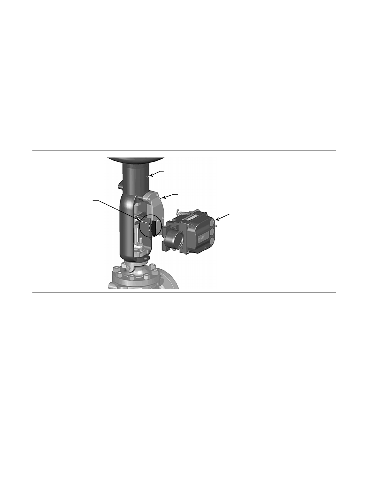
Control Valve Interface
The DVC6200 digital valve controller is mechanically attached to the valve’s actuator by means of a mounting bracket.
The control valve's position is conveyed to the travel sensor of the DVC6200 digital valve controller by means of the
feedback bracket and magnet assembly attached to the actuator’s stem.
ACTUATOR
MOUNTING
FEEDBACK BRACKET
AND MAGNET ASSEMBLY
BRACKET
DVC6200
DIGITAL VALVE
CONTROLLER
X0381-1
Pneumatic tubing connected to the DVC6200 brings instrument supply air to the DVC6200 and takes controlled
output air from the DVC6200 to the actuator. Pressure sensors in the DVC6200 measure these pressure signals and
present them as device variables
Host interface
The input to the DVC6200 can either be twowire 4to20 mA current loop (in pointtopoint mode) or 24 VDC (in
multidrop mode). This input is connected in the DVC6200’s terminal box on two terminals marked “LOOP +” and
“LOOP ”. Refer to the DVC6200 Series quick start guide for connection details.
Pushbutton Calibration
A pushbutton near the wiring terminals in the terminal box provides a quick means to autocalibrate the travel of the
instrument. The button must be pressed for 3 to 10 seconds. Autocalibration will move the valve through the full
range of travel whether the Instrument Mode is In Service or Out of Service. However, if the Write Protection is
Protected, this button will not be active. To abort, press the button again for 1 second. The calibration button is
disabled by default.
4

Instruction Manual Supplement
D103639X012
DVC6200 Digital Valve Controller
September 2019
Internal Jumpers And Switches (Optional)
The input to the DVC6200 is determined by the PtPt/MultiDrop switch on the printed wiring board.
The DVC6200 also has a pair of optional “Output” terminals that can either function as a position transmitter or a
discrete switch. Electrical configuration of the output circuit requires the proper setting of a DIP switch on the
DVC6200’s printed wiring board. Additionally, the functional operation of the output circuit must be configured with
the user interface.
Refer to the DVC6200 instruction manual for additional details on the settings of the selection switches.
WITH OPTIONAL I/O PACKAGE
DIP SWITCH FOR
TRANSMITTER/SWITCH
SELECTION
PT-PT/
MULTI-DROP
SELECTION
PT-PT/
MULTI-DROP
SELECTION
X0432
X0427
X0430
WITHOUT I/O PACKAGE
X0431
OUTPUT+
OUTPUT-
Write Protection
There are two Write Protection states for the DVC6200: Not Protected or Protected. Protected prevents configuration
and calibration changes to the instrument. The default setting is Not Protected. Protection is controlled under
software control. Write Protection can be enabled remotely. However, to disable Write Protection to Not Protected,
you must have physical access to the instrument. The procedure will require you to press a button inside the terminal
box when directed by the software as a security measure.
5
DVC6200 Digital Valve Controller
September 2019
Instruction Manual Supplement
D103639X012
Dynamic Variables
Four Dynamic Variables are implemented.
Default Meaning Units
PV Analog Input mA, %
SV* Travel Setpoint %
TV* Pressure PSI, BAR, KPA, Kg/cm
FV* Travel %
* User selectable
The SV, TV, and FV variables are user selectable via Command 51 to any of the following variables. Variable selections
are listed below:
Variable Units
Travel %
Travel Setpoint %
Pressure Port A PSI, BAR, KPA, Kg/cm
Pressure Port B PSI, BAR, KPA, Kg/cm
Pressure A – B PSI, BAR, KPA, Kg/cm
Supply Pressure PSI, BAR, KPA, Kg/cm
2
2
2
2
Drive Signal %
Analog Input mA, %
2
Device Variables
These variables represent measurements taken by the device, are read only values, and are all in float format. These
can be read with Commands 9, 33, and 54.
Variable ID Meaning Units
0 Analog Input mA, %
1 Internal Temperature _C, _F
2 Pressure Port A PSI, BAR, KPA, Kg/cm
3 Travel %
4 Drive Signal %
5 Pressure Port B PSI, BAR, KPA, Kg/cm
6 Travel Setpoint %
7 Differential Pressure (Port A – Port B) PSI, BAR, KPA, Kg/cm
8 Supply Pressure PSI, BAR, KPA, Kg/cm
9 Implied Valve Position %
10 Primary Feedback (user selected, either Travel or Pressure) %
11 Friction* As defined in ValveLink software
12 Deadband* As defined in ValveLink software
* Only available with PD diagnostic level
2
2
2
2
6
Instruction Manual Supplement
D103639X012
Unit Codes
Variable Units Code Units
0 No Units
6 Pounds per square inch, psi
7 Bar
10 ($0A) Kilograms per square centimeter, kg/cm
12 ($0C) Kilopascals, kPa
32 ($20) Celsius, _C
33 ($21) Fahrenheit, _F
39 ($27) Milliamps, mA
57 ($39) Percent, %
DVC6200 Digital Valve Controller
September 2019
2
Status Information
Device Status
The Field Device Status Byte is the only status byte defined in the HART protocol. The order and meaning of each of the
eight bits within the byte are fixed by the protocol. This byte is one of the status bytes included with each HART
response. It is not part of the Command 48 data.
Bit Name of Status Bit Meaning
7 Field Device Malfunction
6 Configuration Changed
5 Cold Start
4 More Status Active when any bit in command 48 is active.
3 Analog Input Fixed
2 Analog Input Saturated The loop current reading is beyond sensor limits.
1 Internal Sensor Out of Limits
0 Variable Out of Range Set when any variable 0, 1, 2, 3, 5, 8 or 10, is saturated.
Set / cleared by the firmware based on self test results. This bit is set if the
pressure, position or temperature sensors provide invalid readings.
Two such bits exist internally, one for each HART master. Both copies are set
when any variable, HART message, tag, descriptor or date are changed from
HART. Cleared by command 38, separately for each master. This bit survives
loss of power.
Set by the firmware whenever a RESET sequence is executed or at initial
device power up. Cleared by the first HART command. Two such bits exist
internally, one for each HART master.
Active if the Instrument Mode of the DVC6200 is in the “Out Of Service”
condition or if the Control Mode of the DVC6200 is in one of the digital set
point modes.
(This bit is named “NonPrimary Variable Out Of Limits” in the HART
documentation for transmitters. It has been renamed to reflect the fact that
these variables are INTERNAL INPUTS to FIELDVUE products). The firmware
sets this bit when any sensor (pressure, position, temperature) exceeds its
operating limits.
7

DVC6200 Digital Valve Controller
September 2019
Instruction Manual Supplement
D103639X012
Universal Commands
The DVC6200 field device implements all Universal Commands. Commands 14, 15, 17, 48 are listed below to indicate
their unique responses.
Command 0: Read Unique Identifier
Command 1: Read Primary Variable
Command 2: Read Primary Variable (current) and Percent of Range
Command 3: Read Dynamic Variables and Primary Variable (current)
Command 6: Write Polling Address
*Command 7: Read Loop Configuration
*Command 8: Read Dynamic Variable Classifications
*Command 9: Read Device Variable with Status
Command 11: Read Unique Identifier Associated with Tag
Command 12: Read Message
Command 13: Read Tag, Descriptor, Date
Command 14: Read Primary Variable Transducer Information
Command 15: Read Primary Variable Output Information
Command 16: Read Final Assembly Number
Command 17: Write Message
Command 18: Write Tag, Descriptor, Date
Command 19: Write Final Assembly Number
*Command 20: Read Long Tag
*Command 21: Read Unique Identifier Associated with Long Tag
*Command 22: Write Long Tag
Command 38: Reset Configuration Changed Flag
Command 48: Read Additional Status
*Commands 7, 8, 9, 20, 21, and 22 are HART 7 only.
8

Instruction Manual Supplement
D103639X012
DVC6200 Digital Valve Controller
September 2019
Command 14: Read Primary Variable Transducer Information
The transducer limits reported in this command are either 420 milliamps, or 0100%, and reflect the units code most
recently supplied in command 44.
Note
The Transducer Serial Number is not applicable to the DVC6200 and is set to “0”.
Byte Format Description Returned Value
Request
Data
bytes
Response
Data
Bytes
Response
Codes
None
02 UINT24 Transducer Serial Number 000000
3 Enum Transducer Limits and Minimum Span Units Code From Cmd 44
47 Float Upper Transducer Limit 20mA
811 Float Lower Transducer Limit 4.0mA
1215 Float Minimum Span 1.0mA
Code Class Description
None
9
DVC6200 Digital Valve Controller
September 2019
Instruction Manual Supplement
D103639X012
Command 15: Read Primary Variable Output Information
This command returns the upper/lower range values for the primary variable which is defined to be the loop current
signal. These are the loop current values for the ends of physical travel, and are used to derive set point from the loop
current. It reports the range supplied in Command 35.
For example, the lower range, for an increase to open valve, will be the current which will produce a 0% set point.
However, for an increase to close valve, the lower range will be the loop current for a 100% set point.
The range values can be changed via Command 35.
The DVC6200 assumes 0% = 4mA and 100% = 20mA.
Byte Format Description Returned Value
Request
Data bytes
Response
Data Bytes
Additional
Device
Related
Response
Codes
None
PV Alarm Selection Code. The Alarm Selection Code
0 Enum
1 Enum
2 Enum
36 Float AI Upper Range Value From Cmd 35
710 Float AI Lower Range Value From Cmd 35
1114 Float PV Damping Value (units of seconds) 0.0
15 Enum Write Protect Code (0=Disabled, 1=Enabled) 0 or 1
16 Enum Reserved. Must be set to “250”, Not Used. 250
17 Uint8 PV Analog Channel Flags 01
Code Class Description
None
indicates the action taken by the device under error
conditions. For Actuators, the action taken by the
positioner is indicated.
PV Transfer Function Code. The Transfer Function Code
must return “0”, Linear, if transfer functions are not
supported by the device.
AI Upper and Lower Range Values Units Code, as
supplied in command 35.
250 (Not Used)
250 (Not Used)
From CMD 35
10
 Loading...