

IM Supplement: CSA Hazardous Area Approvals-FIELDVUE DVC6005 Series Remote Mount Digital Valve Controllers | Fisher
Fisher IM Supplement: CSA Hazardous Area Approvals-FIELDVUE DVC6005 Series Remote Mount Digital Valve Controllers | Fisher Manuals & Guides
Instruction Manual Supplement
D104209X012
DVC6005 Digital Valve Controllers
August 2017
CSA Hazardous Area Approvals
™
Fisher
FIELDVUE™ DVC6005 Series
Remote Mount Digital Valve Controllers
Hazardous Area Approvals and Special Instructions
for “Safe Use” and Installations in Hazardous Locations
Certain nameplates may carry more than one approval, and each approval may have unique installation/wiring
requirements and/or conditions of “safe use”. These special instructions for “safe use” are in addition to, and may
override, the standard installation procedures. Special instructions are listed by approval type.
Note
This information supplements the nameplate markings affixed to the product and the DVC6005 Series Remote Mount quick start
guide (D103784X012
Approval information is for both aluminum and stainless steel constructions.
Always refer to the nameplate itself to identify the appropriate certification.
), available from your Emerson sales office, Local Business Partner or at Fisher.com.
WARNING
Failure to follow these conditions of “safe use” could result in personal injury or property damage from fire or explosion
and area re‐classification.
Ordinary Locations Approval
Complies with general electrical safety CAN/CSAC22.2 No. 6101012004
SELV, conduit connected, Enclosure Type 4X, IP66, Installation Category I, Pollution Degree 4
DVC6005 Series (HART HW1, F
Rated Input 9-30 VDC, 4-20 mA
Outputs 0-9.6 VDC, 0-3.5 mA
-52_C ≤ Ambient ≤ +80_C
DVC6015, DVC6025, DVC6035
Rated Input 10 VDC max, 3.5 mA max
-60_C ≤ Ambient ≤ 125_C
OUNDATION fieldbus)
www.Fisher.com

DVC6005 Digital Valve Controllers
August 2017
Explosion-proof and Dust Ignition-proof
Class I, Division 1, Groups B,C,D ; Class I, Division 2, Groups A,B,C,D
Class II, Division 1, Groups E,F,G ; Class II, Division 2, Groups F,G
Class III, Division 1
Ex d IIC
Ex nC IIC (DVC6005 Series)
Ex nA IIC (DVC6015, DVC6025, DVC6035)
Type 4X, IP66
Single Seal Device (HART HW2 with I/O Package pending)
Instruction Manual Supplement
D104209X012
DVC6005 Series (HART HW1 & HW2, F
OUNDATION FIELDBUS)
Rated input 30 Vmax, 20 mA
- 52_C ≤ Ambient ≤ + 80_C
Max inlet pressure 10 bar (145 psig) (air or natural gas)
Temperature Code: T6 (Tamb ≤ 75_C), T5 (Tamb ≤ 80_C)
DVC6015, DVC6025, DVC6035
Rated input 10 Vmax, 5 mA
- 60_C ≤ Ambient ≤ + 125_C
Temperature Code: T6 (Tamb ≤ 80_C), T5 (Tamb ≤ 95_C), T4 (Tamb ≤ 125_C)
Intrinsically Safe
Class I, Division 1, Groups A,B,C,D
Class II, Division 1, Groups E,F,G
Class III, Division 1
Ex ia IIC
Type 4X, IP66
Single Seal Device (HART HW2 with I/O Package pending)
DVC6005 Series (HART HW1 & HW2, F
Rated input 30 V DC max, 20 mA
- 52_C ≤ Ambient ≤ + 80_C
Max inlet pressure 10 bar (145 psig) (air or natural gas)
DVC6015, DVC6025, DVC6035
Rated input 10 Vmax, 5 mA
- 60_C ≤ Ambient ≤ + 125_C
Intrinsically safe when connected per installation drawing GE42818, as shown in the following figures
DVC6005 HW1 and DVC6015, DVC6025, DVC6035 figure 1 and 4...........
DVC6005 HW2 and DVC6015, DVC6025, DVC6035 figure 2 and 4...........
DVC6005f and DVC6015, DVC6025, DVC6035 figure 3 and 4................
OUNDATION FIELDBUS)
2
Instruction Manual Supplement
DVC6005 Digital Valve Controllers
D104209X012
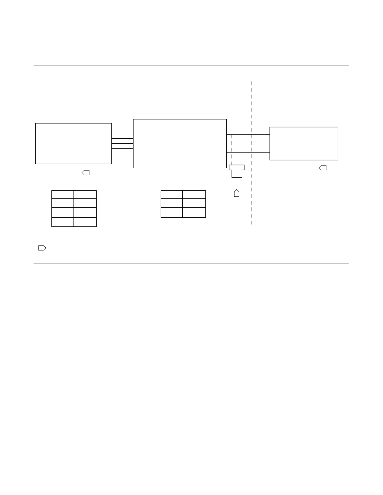
Figure 1. CSA Loop Schematics FIELDVUE DVC6005 HW1 and DVC6015, DVC6025, DVC6035
August 2017
CLASS I, ZONE 0, GROUP IIC
CLASS I, DIV 1, GROUPS ABCD
CLASS II, DIV 1, GROUPS EFG
CLASS III
DVC6015, DVC6025, DVC6035
Vmax = 30 VDC
Imax = 100 mA
Ci = 0 uF
Li = 0 mH
Pi = 160 mW
NOTE 1
T CODE T (amb)
T4 ≤ 125_C
T5 ≤ 95_C
T6 ≤ 80_C
1 SEE NOTES IN FIGURE 4
GE42818 Sheet 5, Rev. F
1
CLASS I, ZONE 0, GROUP IIC
CLASS I, DIV 1, GROUPS ABCD
CLASS II, DIV 1, GROUPS EFG
CLASS III
DVC6005
Voc = 30 VDC
Isc = 12 mA
Ca = 66 nF
La = 246 mH
Po = 86 mW
Vmax = 30 VDC
Imax = 226 mA
Ci = 5 nF
Li = 0.55 mH
Pi = 1.4 W
T CODE T (amb)
T5 ≤ 80_C
T6 ≤ 75_C
HAZARDOUS LOCATION
NOTE 7
1
NON‐HAZARDOUS LOCATION
CSA APPROVED BARRIER
NOTE 1, 3, 4, 5, 6
1
3
 Loading...