

Fisher FSKIF-121AE2-EU, FSKIF-184AE2-EU, FSKIF-243AE2, FSKIF-301AE2, FSKIF-362AE2 Service Manual
...Page 1

Service Manual
SUPER DC INVERTER LCAC SERIES
/Energy Related Products/
CASSETTE
FSKIF-121AE2-EU
FSKIF-184AE2-EU
FSKIF-243AE2
FSKIF-301AE2
FSKIF-362AE2
FSKIF-481AE0
FSKIF-601AE0
Duct
FSLIF-182AE2
FSLIF-242AE2
FSLIF-301AE2
FSLIF-362AE2
FSLIF-481AE0
FSLIF-602AE0
ceiling /floor
FSPIF-181AE2
FSPIF-241AE2
FSPIF-301AE2
FSPIF-362AE2
FSPIF-480AE0
FSPIF-601AE0
Console
FSFIF-121AE2
Outdoor
FSOIF-121AE2
FSOIF-183AE2
FSOIF-243AE2
FSOIF-301AE2
FSOIF-362AE2-3F
FSOIF-482AE0-3F
FSOIF-602AE0-3F
NOTE:
Before servicing the unit, please read this at first.
Always contact with your service center if meet problem.
FI_SM_LCAC_UNITS_2016_161206
Page 2

Contents
Contents i
Part 1 General Information ....................................................... 1
Part 2 Indoor Units ................................................................ 6
Part 3 Outdoor Units ........................................................... 71
Part 4 Installation .............................................................. 84
Part 5 Electrical Control System .....................................116
※The specifications, designs, and information in this book are subject to change without notice for
product improvement.
Page 3

General Information
General Information 1
Part 1
General Information
1. Model Lists ............................................................................................ 2
2. External Appearance ............................................................................ 3
2.1 Indoor Units ............................................................................................................... 3
2.2 Outdoor Units ............................................................................................................ 4
Page 4
Model Lists
2 General Information
1. Model Lists
1.1 Indoor Units
R410A (capacity multiplied by 1000Btu/h)
Type
Super slim cassette Cooling and heating ● ● ● ● ● ●
Duct Cooling and heating ● ● ● ● ● ●
Ceiling-floor Cooling and heating ● ● ● ● ●
Four-way cassette(compact) Cooling and heating ● ●
Console Cooling and heating ●
1.2 Outdoor Units
Universal Outdoor unit Model Compressor type Compressor Brand Matched indoor units
12
18
24 30
36
48
60
FSOIF-362AE2-3F
FSOIF-482AE0-3F
FSOIF-602AE0-3F
Rotary
GMCC
Rotary
GMCC
Rotary
GMCC
Rotary
GMCC
Rotary
GMCC
Rotary
GMCC
Rotary
GMCC
FSOIF-121AE2
FSOIF-183AE2
FSOIF-243AE2
FSOIF-301AE2
FSFIF-121AE2
FSKIF-121AE2-EU
FSLIF-182AE2
FSPIF-181AE2
FSKIF-184AE2-EU
FSLIF-242AE2
FSPIF-241AE2
FSKIF-243AE2
FSLIF-301AE2
FSPIF-301AE2
FSKIF-301AE2
FSLIF-362AE2
FSPIF-362AE2
FSKIF-362AE2
FSLIF-481AE0
FSPIF-480AE0
FSKIF-481AE0
FSLIF-602AE0
FSPIF-601AE0
FSKIF-601AE0
Page 5
External Appearance
General Information 3
2. External Appearance
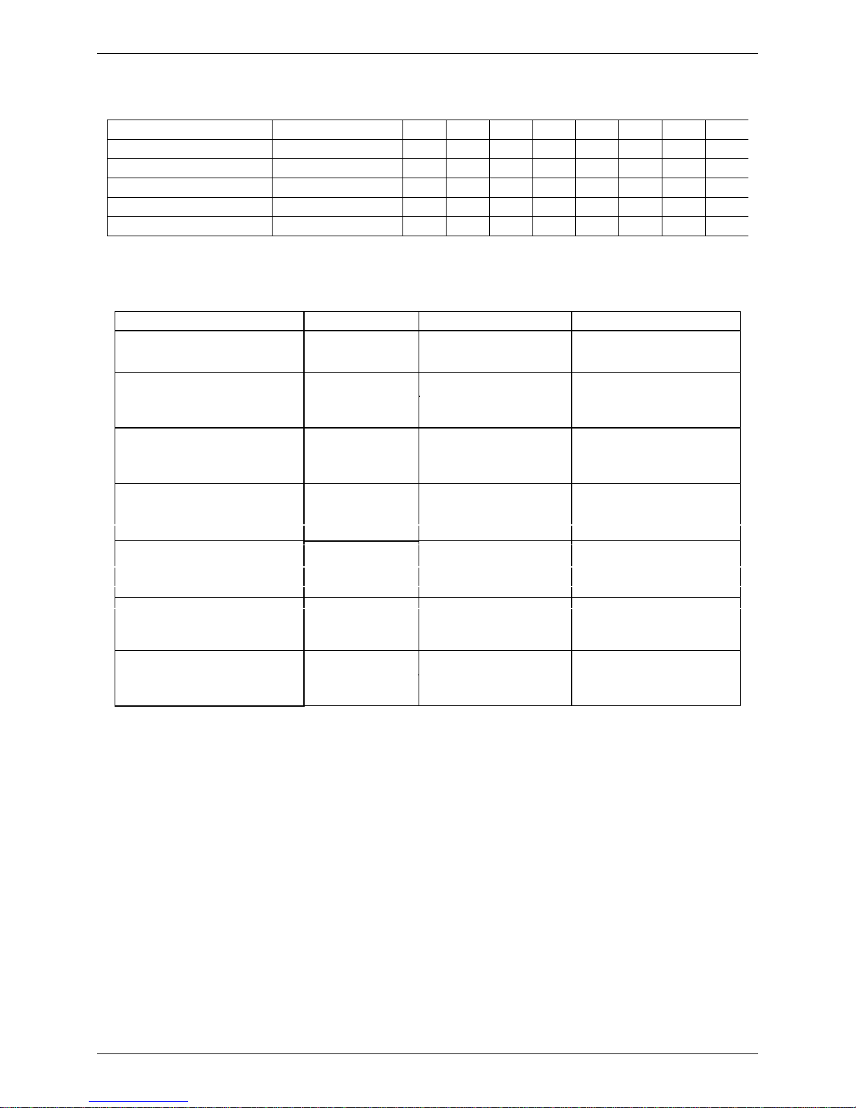
2.1 Indoor Units
Super slim cassette
Duct
Ceiling-Floor Compact Four-way cassette
Console
Page 6
External Appearance
4 General Information
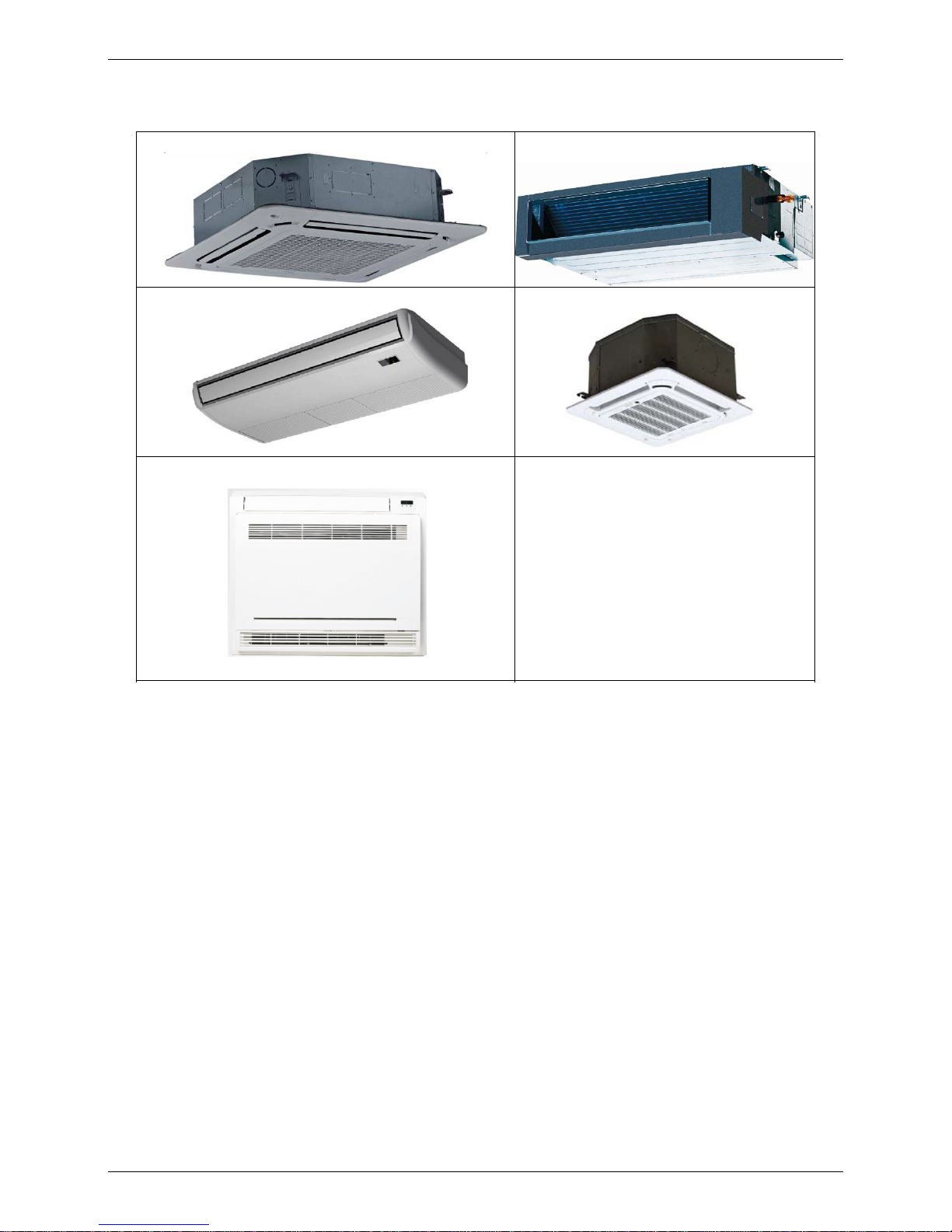
2.2 Outdoor Units
Single fan outdoor unit
Double fan outdoor unit
Page 7

Indoor Units
5
Indoor Units
Part 2
Indoor Units
Super Slim Cassette Type ................................................... 7
Duct Type ............................................................................. 20
Ceiling & Floor Type ........................................................... 37
Four-way Cassette Type (Compact) .................................. 53
Console Type ....................................................................... 60
Page 8

Super Slim Cassette Type
Indoor Units
6
Super Slim Cassette Type
1. Features .............................................................................. 7
2. Dimensions ....................................................................... 9
3. Service Space .................................................................. 10
4. Air Velocity Distributions (Reference Data) ................. 11
5. Electric Characteristics .................................................. 14
6. Sound Levels ................................................................... 15
7. Accessories ..................................................................... 16
8. The Specification of Power ............................................ 17
9. Field Wiring ..................................................................... 18
10. Wiring diagram .............................................................. 19
Page 9
Features
7
Indoor Units
1. Features
1.1 Overview
Compact design, super slim body size, less space requiring in installation
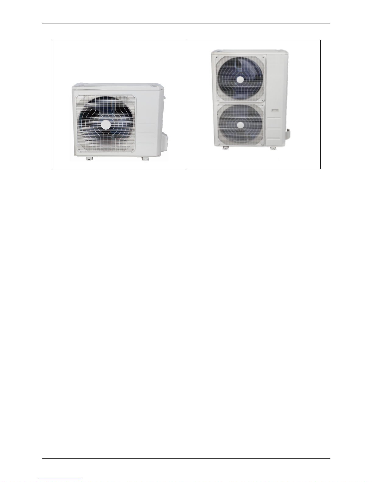
1.2
Fresh air intake function
Fresh air fulfills air quality more healthy and comfortable.
Ventilation motor is optional to increase the effect of fresh air.
1.3 Optional ventilator connector
VVeennttiillaattiioon
n
mmoottoor
r
ccoonnnneeccttoor
r
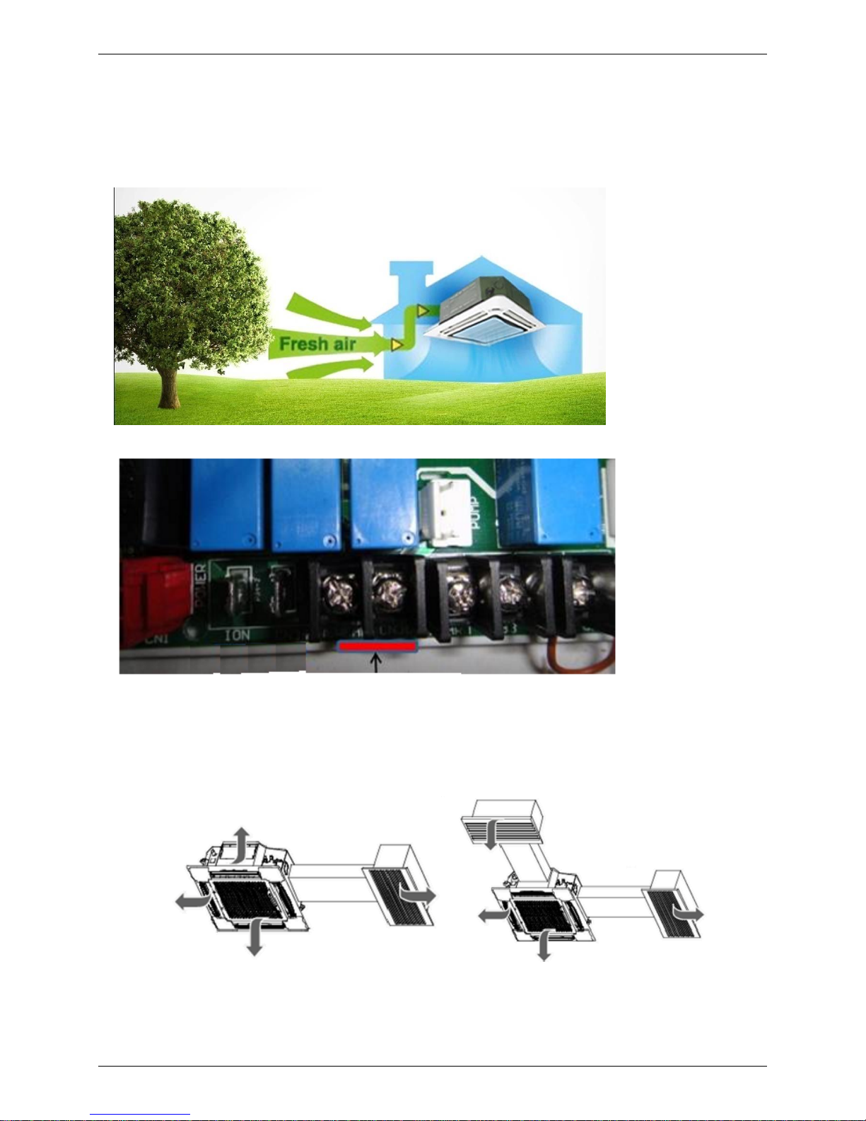
1.4 External air duct design
Reserve external air duct, more flexible for the air supply.
Page 10

Features
Indoor Units
8
1.5
Built-in draining pump
Due to the improvement of structure, more convenient to repair or replace the draining pump.
Built-in draining pump to make sure condensed water drain out reliably.
Draining Pump
Alarm lamp
Long-distance on-off controller
1.6 Terminals for alarm lamp and long-distance on-off controller connection are
standard
Reserve terminals for the connection of alarm lamp and long-distance on-off controller, more human
control.
1.7 Twins Combination(18k-30k)
The units can be installed as Twin systems: one outdoor unit can connect with two indoor units. The
indoor units can be combined in any of the different available ratings.
Page 11

Dimensions
Indoor Units 9
2. Dimensions
840
840
950
950
C
Test mouth &
Test cover
Drain hole
32
Wiring connection port
680
780
780
680
136
126
91
196
132
A
A
B
A
A
B
A
A
B
A
B
Service hole for
draining pump
Fresh air intake
75
55
80
80
4-install hanger
Gas side
Liquid side
E-parts box
135
90
Panel
Body
92929292
D
D
92 92
D
D
D
D
92
9292
92
92 92
92
92
D
D
Unit: mm
Model A B C D
160 95 245 60
160 95 287 60
FSKIF-243AE2
FSKIF-301AE2
FSKIF-362AE2
FSKIF-481AE0
FSKIF-601AE0
Page 12
Service Space
10 Indoor Units
3. Service Space
>1000mm
>1000mm
>1000mm
>1000mm
Page 13
Air Velocity Distributions (Reference Data)
Indoor Units 11
4.
Air Velocity Distributions (Reference Data)
24K:
Cooling:
Heating:
Page 14
Air Velocity Distributions (Reference Data)
12 Indoor Units
30-36K:
Cooling:
Heating:
Page 15
Air Velocity Distributions (Reference Data)
Indoor Units 13
48-60K:
Cooling:
Heating:
Page 16

Electric Characteristics
14 Indoor Units
5.
Electric Characteristics
Model
Indoor Unit
Power
Supply
Hz Voltage Min Max MFA
Notes:
MFA: Max. Fuse Amps. (A)
50
220-240 198
254
10
FSKIF-243AE2
FSKIF-301AE2
FSKIF-362AE2
FSKIF-481AE0
FSKIF-601AE0
50
220-240 198
254
10
50
220-240 198
254
10
50
220-240 198
254
10
50
220-240 198
254
10
Page 17
Sound Levels
Indoor Units 15
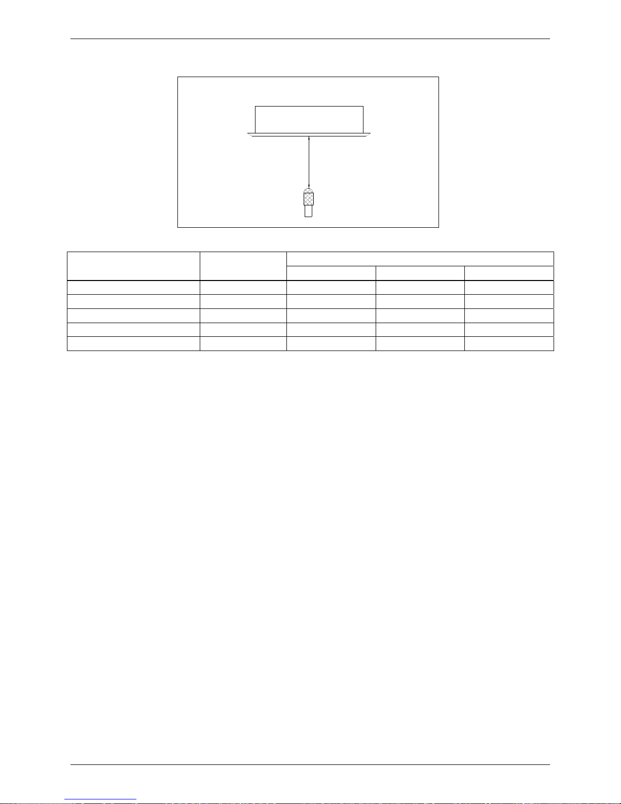
6.
Sound Levels
1.4m
Microphone
Model Noise Power dB(A)
Noise level dB(A)
H M L
61
64
61
63
68
FSKIF-243AE2
FSKIF-301AE2
FSKIF-362AE2
FSKIF-481AE0
FSKIF-601AE0
46
53
53
55
52
42
48
50
51
49
39
44
47
48
46
Page 18

Accessories
16 Indoor Units
7.
Accessories
Name Shape Quantity
Installation Fittings
Installation paper board
1
Tubing & Fittings
Soundproof / insulation sheath
1
Drainpipe Fittings
Out-let pipe sheath
1
Out-let pipe clasp 1
Drain joint 1
Seal ring 1
Remote controller & Its
Frame(The product you
have might not be
provided the following
accessories)
Remote controller & Its Frame
1
Remote controller holder 1
Mounting screw(ST2.9×10-C-H) 2
Remote controller manual 1
Alkaline dry batteries (AM4)
2
Others
Owner's manual 1
Installation manual 1
Installation accessory
(The product you have
might not be provided the
following accessories
Expansible hook
4
Installation hook
4
Orifice
1
Page 19

The Specification of Power
Indoor Units 17
8. The Specification of Power
36000 Btu/h
INDOOR UNIT
POWER
Frequency and
Voltage
220-240V, 50Hz 220-240V, 50Hz 220-240V, 50Hz 220-240V, 50Hz
POWER WIRING
(mm2)
CIRCUIT BREAKER
/ Fuse (A)
15/10 15/10 15/10 15/10
OUTDOOR UNIT
POWER
Frequency and
Voltage
220-240V, 50Hz 220-240V, 50Hz 380-420V, 50Hz
POWER WIRING
(mm2)
CIRCUIT BREAKER
/ Fuse (A)
Indoor/Outdoor Connecting Wiring
(Weak Electric Signal) (mm2)
2×0.2 (shielded)
Indoor/Outdoor Connecting Wiring
(Strong Electric Signal) (mm2)
INDOOR UNIT
POWER
Frequency and
Voltage
Power Wiring
(mm
2
)
Circuit Breaker/Fuse
(A)
OUTDOOR UNIT
POWER
Frequency and
Voltage
Power Wiring
(mm
2
)
Circuit Breaker/Fuse
(A)
Indoor/Outdoor Connecting Wiring
(Weak Electric Signal) (mm
2
)
Indoor/Outdoor Connecting Wiring
(Strong Electric Signal) (mm2)
30000 Btu/h
24000 Btu/h
Phase
1-phase
3-phase
3-phase
48000 Btu/h
1-phase
1-phase
1-phase
1-phase
1-phase
Phase
380-420V, 50Hz
3x2,5
3x4,0
5x2,5
5x2,5
3x1,5
3x1,5
3x1,5
3x1,5
30/20
30/25
3x 20/16
3x 20/16
2×0.2 (shielded)
2×0.2 (shielded)
2×0.2 (shielded)
Model
60000 Btu/h
Model
1-phase
Phase
3-phase
Phase
380-420V, 50Hz
380-420V, 50Hz
2×0.2 (shielded)
3x1,5
5x2,5
3x 30/20
15/10
Page 20
Field Wiring
18 Indoor Units
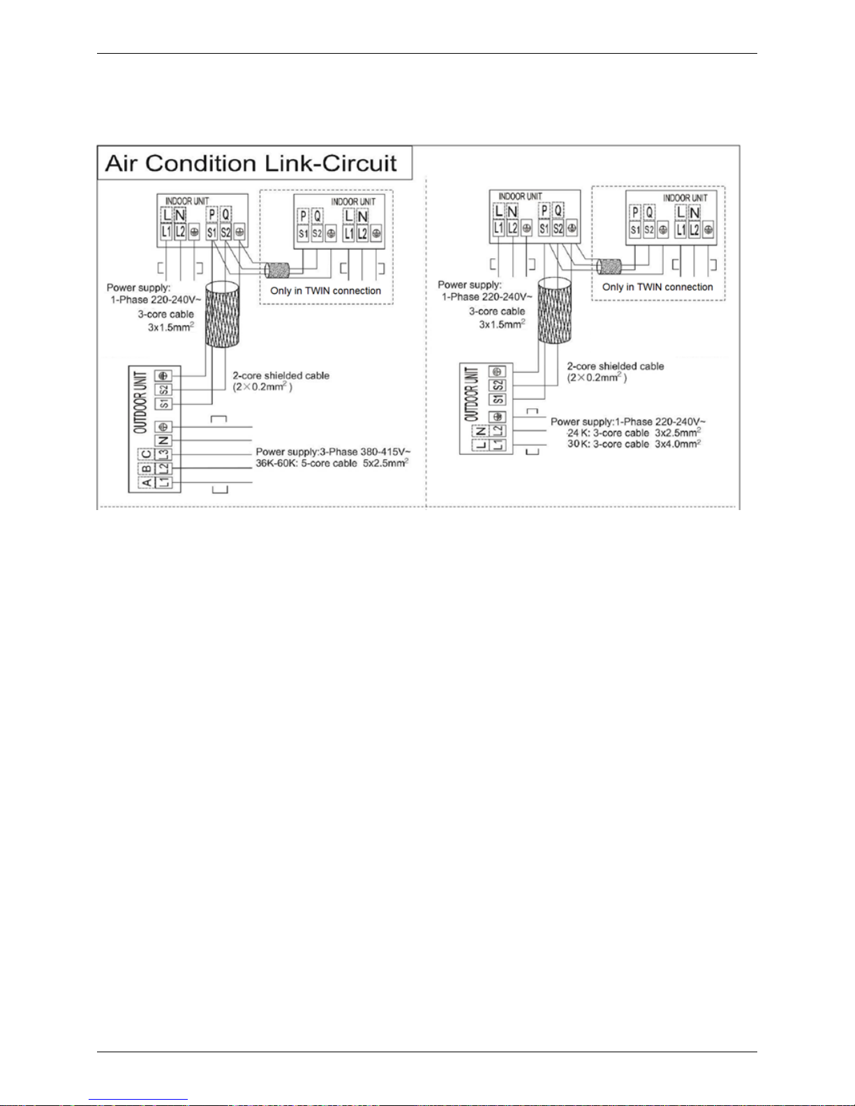
9. Field Wiring
Page 21
Wiring diagram
Indoor Units 19
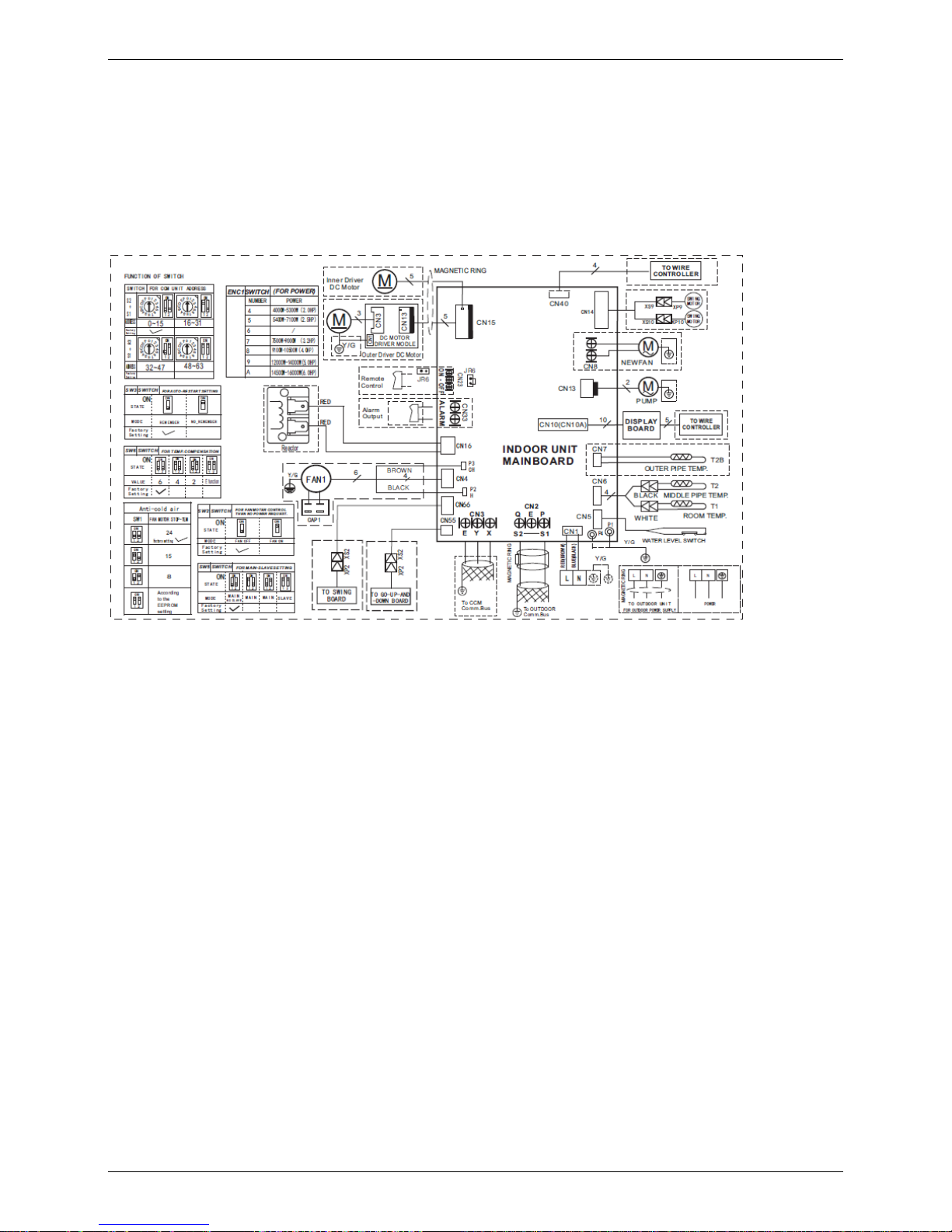
10. Wiring diagram
FSKIF-243AE2
FSKIF-301AE2
FSKIF-362AE2
FSKIF-481AE0
FSKIF-601AE0
Page 22

Duct Type
20 Indoor Units
Duct Type
1. Features ............................................................................ 21
2. Dimensions ...................................................................... 24
3. Service Space .................................................................. 25
4. Static Pressure ................................................................ 26
5. Electric Characteristics .................................................. 29
6. Sound Levels ................................................................... 30
7. Accessories ..................................................................... 31
8. The Specification of Power ............................................ 32
9. Field Wiring ..................................................................... 33
10. Wiring Diagram ............................................................. 34
Page 23
Features
Indoor Units 21
1.
Features
1.1 Installation accessories: (Optional)
Front Board, Filter for easy installation
1.2 Easy Installation: Two air inlet styles (Bottom side or Rear side)
Air inlet from rear is standard for all capacity; air inlet from bottom is optional.
The size of air inlet frame from rear and bottom is same, it’s very easy to move the cover from bottom to
rear side, or from rear to the bottom, in order to matching the installation condition.
1.3 Fresh air intake function(Optional for 18~60k)
Install one duct from the reserved fresh-air intake to outdoor.
Continually inhale the fresh air to improve the quality of the indoor air, fulfills air quality more healthy and
comfortable.
1.4 Easy maintenance
Clean the filter (Optional, standard product without filter)
It is easy to draw out the filter from the indoor unit for cleaning, even the filter is installed in rear side or
bottom side.
Front Board
Filter
Air intake from rear (Standard)
Air intake from bottom (Optional)
Page 24
Features
22 Indoor Units
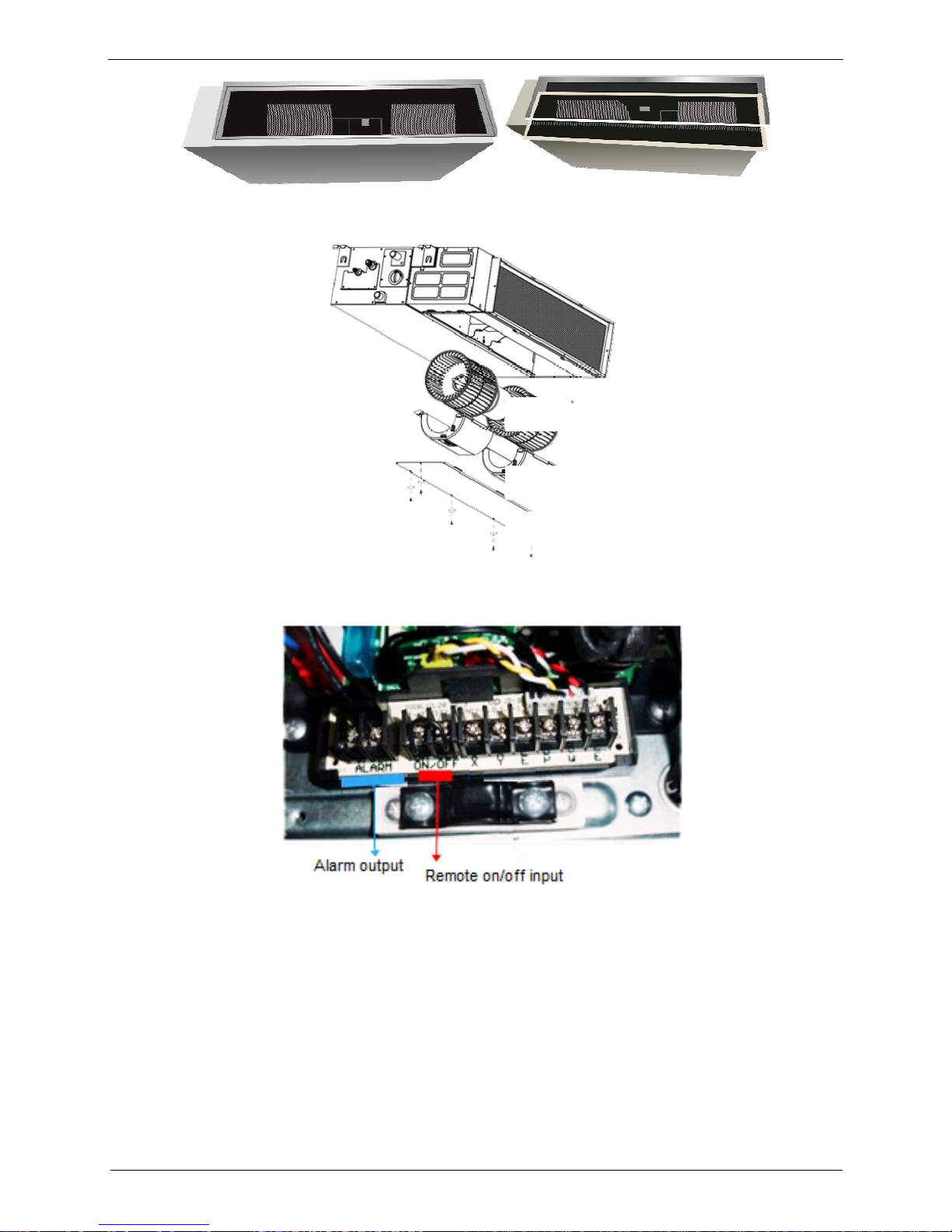
Replace the motor or centrifugal fan
Remove the ventilated panel firstly. Remove a half of blower housing and take out the motor with
centrifugal fan. Directly remove two bolts, and then replace the motor or centrifugal fan easily.
1.5 Reserved remote on-off and alarm ports
Reserved remote on-off ports and alarm port can connect the cable of an on-off controller or an
alarm to realize remote on-off or remote display alarm function.
1.6 Built-in drain pump (Optional):
Built-in drain pump can lift the water to 750mm upmost. It’s convenient to install drainage piping under
most space condition.
Motor
Blower Housing
Ventilated Panel
Page 25

Features
Indoor Units 23
1.7 Built-in display board
The standard indoor unit can be controlled by wired controller.
There is a display board with a receiver in the E-box. Move out the display, and fix it in other place, even
in the distance of 10m. The unit will realized remoter control.
The wired controller and the display board can display the error code or production code when the chips
detect some failure.
1.8 Twins Combination
The units can be installed as Twin systems: one outdoor unit can connect with two indoor units. The
indoor units can be combined in any of the different available ratings.
Display
750mm upmost
Wired Controller (Standard)
Remote Controller (Optional)
Page 26
Dimensions
24 Indoor Units
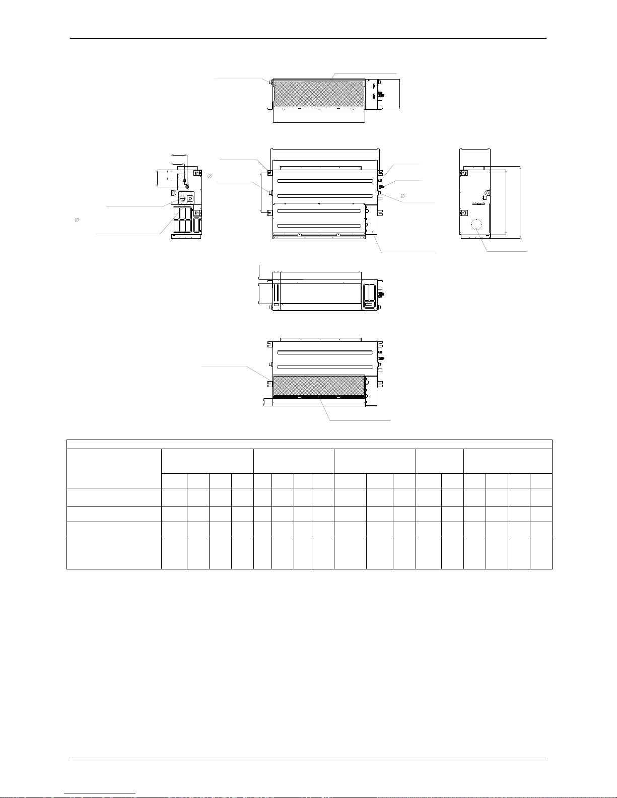
2.
Dimensions
A
C
B
D
J
I
K
Air filter ( optional )
air inlet from rear side
air inlet from bottom side
FE
G
H
Electric control box
Air filter ( optional )
L
4-install hanger
Gas side
Liquid side
M
W1
W2
H1
H2
25 Drain connecting pipe
( for pump )
Test mouth & Test cover
Fresh air intake
25 Drain pipe
25 Drain pipe
Note: standard product without filter Unit: mm
Model
Outline dimension(mm) Air outlet opening size Air return opening size
Size of
install
hanger
Size of refrigerant pipe
A B C D E F G H I J K L M H1 H2 W1 W2
920 270 635 570 65 713 35 179 815 260 20 960 350 120 143 95 150
1200 300 865 800 80 968 40 204 1094 288 45 1240 500 175 198 155 210
FSLIF-182AE2
FSLIF-242AE2
FSLIF-301AE2
FSLIF-362AE2
FSLIF-481AE0
FSLIF-602AE0
1140
270 775
710
65
933
179
35 1065
260
45
1240
500
120
143
95
150
Page 27
Service Space
Indoor Units 25
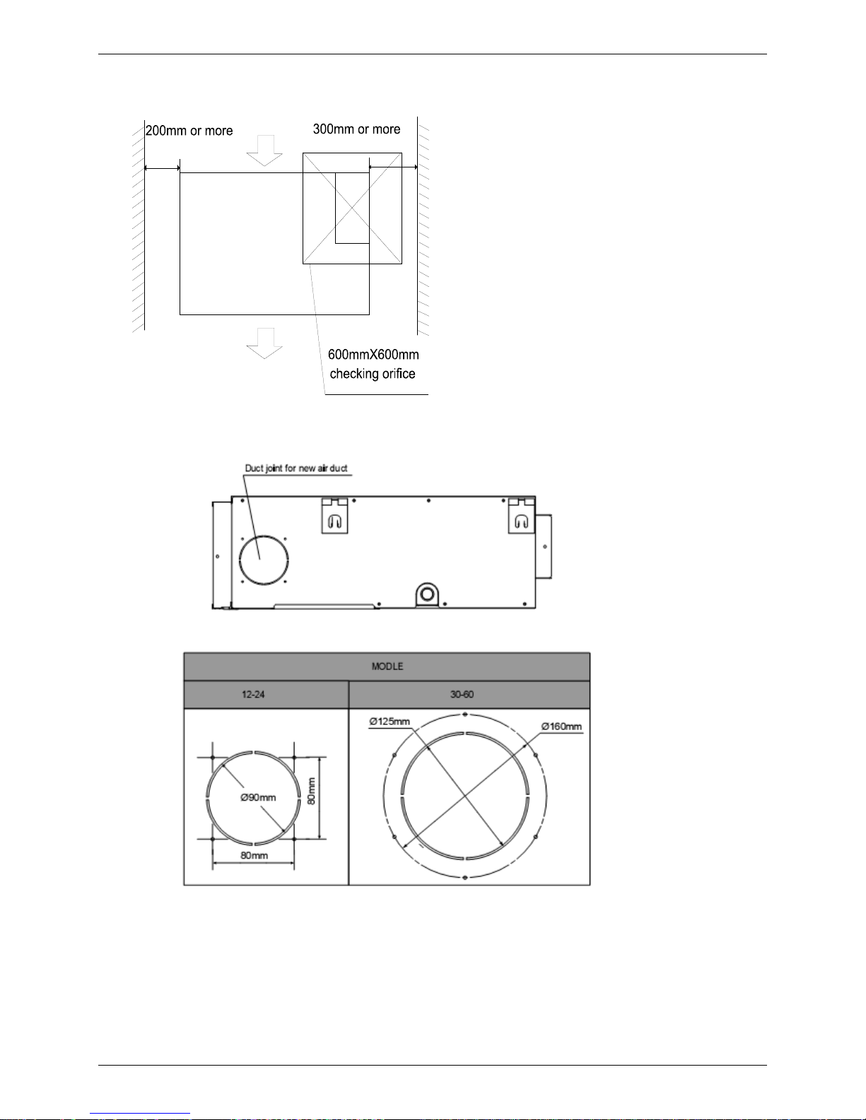
3.
Service Space
Ensure enough space required for installation and maintenance.
All the indoor units reserve the hole to joint the fresh air pipe. The hole size as following:
Page 28
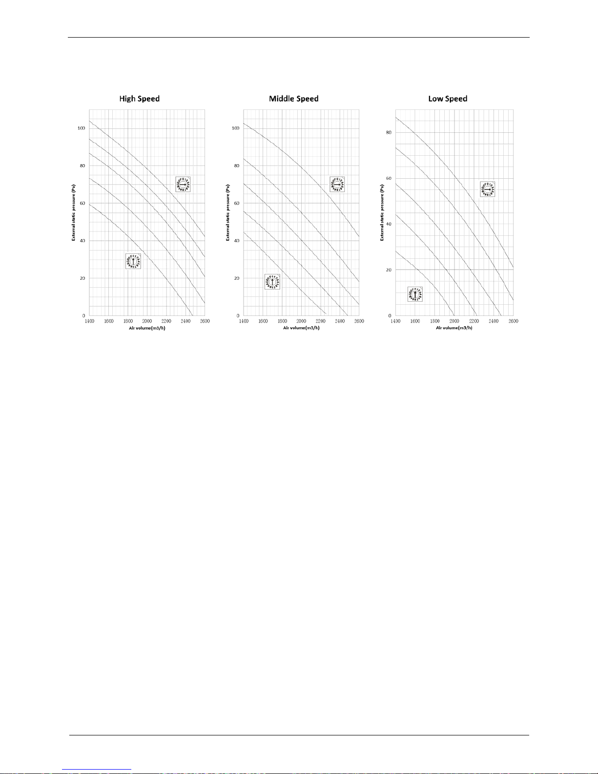
Static Pressure
26 Indoor Units
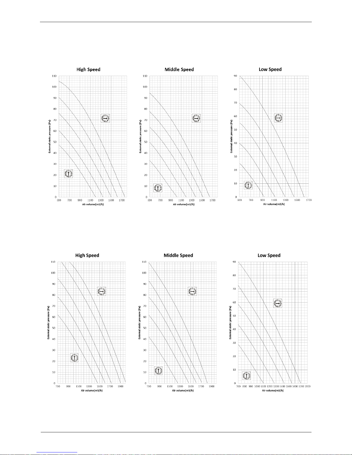
4.
Static Pressure
FSLIF-182AE2
FSLIF-242AE2
Page 29

Static Pressure
Indoor Units 27
FSLIF-301AE2
FSLIF-362AE2
Page 30
Static Pressure
28 Indoor Units
FSLIF-481AE0
FSLIF-602AE0
Page 31

Electric Characteristics
Indoor Units 29
5.
Electric Characteristics
Model
Indoor Unit Power Supply
Hz Voltage Min. Max. MFA
Note:
MFA: Max. Fuse Amps. (A)
FSLIF-182AE2
FSLIF-242AE2
FSLIF-301AE2
FSLIF-362AE2
FSLIF-481AE0
FSLIF-602AE0
50
220-240 198
254
10
50
220-240 198
254
10
50
220-240 198
254
10
50
220-240 198
254
10
50
220-240 198
254
10
50
220-240 198
254
10
Page 32

Sound Levels
30 Indoor Units
6.
Sound Levels
Suction
Discharge
Microphone
1.4m
Concealed Duct Type
DuctDuct
Model
Sound Power
dB(A)
Noise level dB(A)
H M L
FSLIF-182AE2
FSLIF-242AE2
FSLIF-301AE2
FSLIF-362AE2
FSLIF-481AE0
FSLIF-602AE0
58
44
40
37
62
46
42
38
65
50
48
44
59
48
45
40
68
50
47
44
69
50
47
45
Page 33

Accessories
Indoor Units 31
7. Accessories
Name Shape Quantity
Tubing & Fittings
Soundproof / insulation sheath
2
Binding tape
1
Seal sponge
1
Drainpipe Fittings
(for cooling & heating)
Drain joint
1
Seal ring
1
Wired controller & Its Frame
Wired controller
1
Others
Owner,s manual
1
Installation manual
1
EMS & It’s fitting
Magnetic ring (twist the electric wires L
and N around it to five circles)
1
Page 34

The Specification of Power
32 Indoor Units
8.
The Specification of Power
36000 Btu/h
INDOOR UNIT
POWER
Frequency and
Voltage
220-240V, 50Hz 220-240V, 50Hz 220-240V, 50Hz 220-240V, 50Hz
POWER WIRING
(mm2)
CIRCUIT BREAKER
/ Fuse (A)
15/10 15/10 15/10 15/10
OUTDOOR UNIT
POWER
Frequency and
Voltage
220-240V, 50Hz 220-240V, 50Hz 220-240V, 50Hz 380-420V, 50Hz
POWER WIRING
(mm2)
CIRCUIT BREAKER
/ Fuse (A)
Indoor/Outdoor Connecting Wiring
(Weak Electric Signal) (mm2)
2×0.2 (shielded)
Indoor/Outdoor Connecting Wiring
(Strong Electric Signal) (mm2)
INDOOR UNIT
POWER
Frequency and
Voltage
Power Wiring
(mm
2
)
Circuit Breaker/Fuse
(A)
OUTDOOR UNIT
POWER
Frequency and
Voltage
Power Wiring
(mm
2
)
Circuit Breaker/Fuse
(A)
Indoor/Outdoor Connecting Wiring
(Weak Electric Signal) (mm
2
)
Indoor/Outdoor Connecting Wiring
(Strong Electric Signal) (mm2)
30000 Btu/h
24000 Btu/h
Phase
1-phase
3-phase
3-phase
48000 Btu/h
1-phase
1-phase
1-phase
1-phase
1-phase
Phase
380-420V, 50Hz
3x2,5
3x4,0
5x2,5
5x2,5
3x1,5
3x1,5
3x1,5
3x1,5
20/16
30/25
3x 20/16
3x 20/16
2×0.2 (shielded)
2×0.2 (shielded)
2×0.2 (shielded)
Model
Model
Phase
Phase
60000 Btu/h
1-phase
3-phase
380-420V, 50Hz
2×0.2 (shielded)
3x1,5
5x2,5
3x 30/20
15/10
220-240V, 50Hz
220-240V, 50Hz
15/10
18000 Btu/h
1-phase
3x1,5
1-phase
2×0.2 (shielded)
3x2,5
30/20
Page 35

Field Wiring
Indoor Units 33
9.
Field Wiring
Page 36

Wiring Diagram
34 Indoor Units
10.
Wiring Diagram
FSLIF-182AE2,
FSLIF-242AE2,
FSLIF-301AE2,
FSLIF-481AE0,
FSLIF-602AE0
Page 37

Wiring Diagram
Indoor Units 35
FSLIF-362AE2,
Page 38

Wiring Diagram
36 Indoor Units
Page 39

Ceiling & Floor Type
Indoor Units 37
Ceiling & Floor Type
1. Features ............................................................................... 38
2. Dimensions ...................................................................... 39
3. Service Space .................................................................. 40
4. Electric Characteristics .................................................. 41
5. Sound Levels ................................................................... 41
6. Air Velocity and Temperature Distributions................
42
7.
Accessories ................................................................ 48
8.
The Specification of Power ....................................... 48
9.
Field Wiring ................................................................. 49
10. Wiring diagram................................................................ 50
Page 40

Features
38 Indoor Units
1. Features
1.1. New design, more modern and elegant appearance.
1.2. Convenient installation
--The ceiling type can be easily installed into a corner of the ceiling even if the ceiling is very narrow
--It is especially useful when installation of an air conditioner in the center of the ceiling is impossible
due to a structure such as one lighting.
1.3. Two direction auto swing (vertical & horizontal) and wide angle air flow,
--Air flow directional control minimizes the air resistance and produces wilder air flow to vertical
direction.
--The range of horizontal air discharge is widened which secures wider air flow distribution to provide
more comfortable air circulation no matter where the unit is set up
1.4. Three level fan speed, more humanism design, meets different air-supply requirement.
1.5. New foam drain pan with plastic-spraying inner surface
1.6. Easy operation.
1.7. Remote control and optional wired control method.
Page 41

Dimensions
Indoor Units 39
2. Dimensions
A
B
220222
C
120
2
-
4
0
120
140
2
-
3
3
Wiring connection port
204
94
Fresh air intake
Drain discharge port
Refrigerant pipe hole
Hanging arm
D
Capacity (Btu/h)
A B C D
1068 675 235 983
1650 675 235 1565
FSPIF-181AE2
FSPIF-241AE2
FSPIF-301AE2
FSPIF-362AE2
FSPIF-480AE0
FSPIF-601AE0
1285
1200
235
675
Page 42

Service Space
40 Indoor Units
3. Service Space
Page 43

Electric Characteristics
Indoor Units 41
4. Electric Characteristics
5. Sound Levels
Microphone
1m
1m
Air outlet side
1.5m
1m
Microphone
Ceiling Floor
Model
Sound Power
dB (A)
Noise level dB(A)
H M L
FSPIF-181AE2
FSPIF-241AE2
FSPIF-301AE2
FSPIF-362AE2
FSPIF-480AE0
FSPIF-601AE0
57
44
39
34
63
53
48
42
64
54 49
44
63
52
46
40
66
56
48
41
70
55
50
45
FSPIF-181AE2
FSPIF-241AE2
FSPIF-301AE2
FSPIF-362AE2
FSPIF-480AE0
FSPIF-601AE0
Model
Indoor Unit Power Supply
Hz Voltage Min. Max. MFA
Note:
MFA: Max. Fuse Amps. (A)
50
220-240 198
254
10
50
220-240 198
254
10
50
220-240 198
254
10
50
220-240 198
254
10
50
220-240 198
254
10
50
220-240 198
254
10
Page 44

Air Velocity and Temperature Distributions (Reference Data)
42 Indoor Units
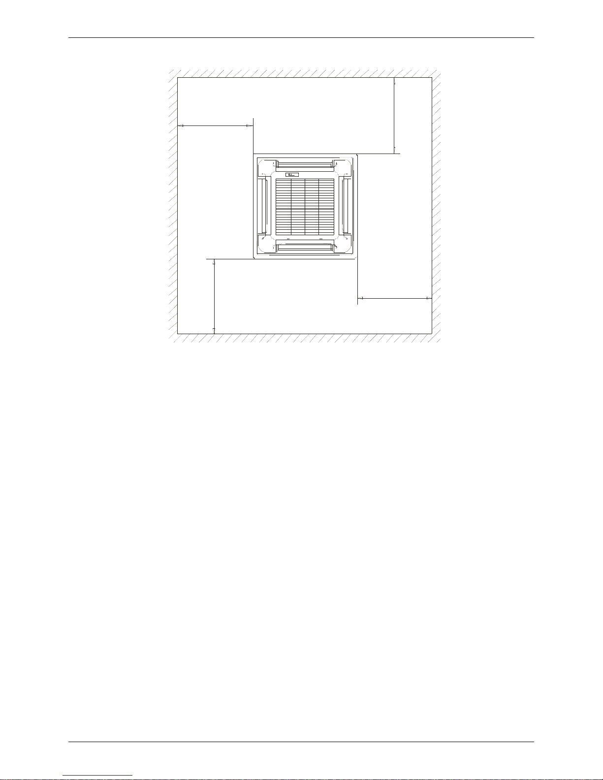
6. Air Velocity and Temperature Distributions (Reference Data)
Model:
Ceiling installation:
Discharge angle 17°
Discharge angle 50°
FSPIF-181AE2,
FSPIF-241AE2
Page 45

Air Velocity and Temperature Distributions (Reference Data)
Indoor Units 43
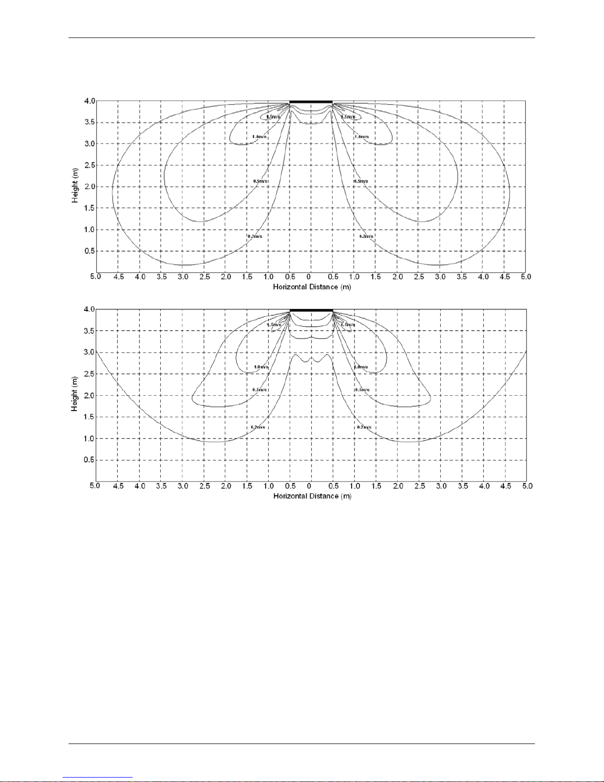
Floor installation:
Discharge angle 17°
Discharge angle 50°
Page 46

Air Velocity and Temperature Distributions (Reference Data)
44 Indoor Units
Model:
Ceiling installation:
Discharge angle 17°
Discharge angle 50°
FSPIF-301AE2,
FSPIF-362AE2
Page 47

Air Velocity and Temperature Distributions (Reference Data)
Indoor Units 45
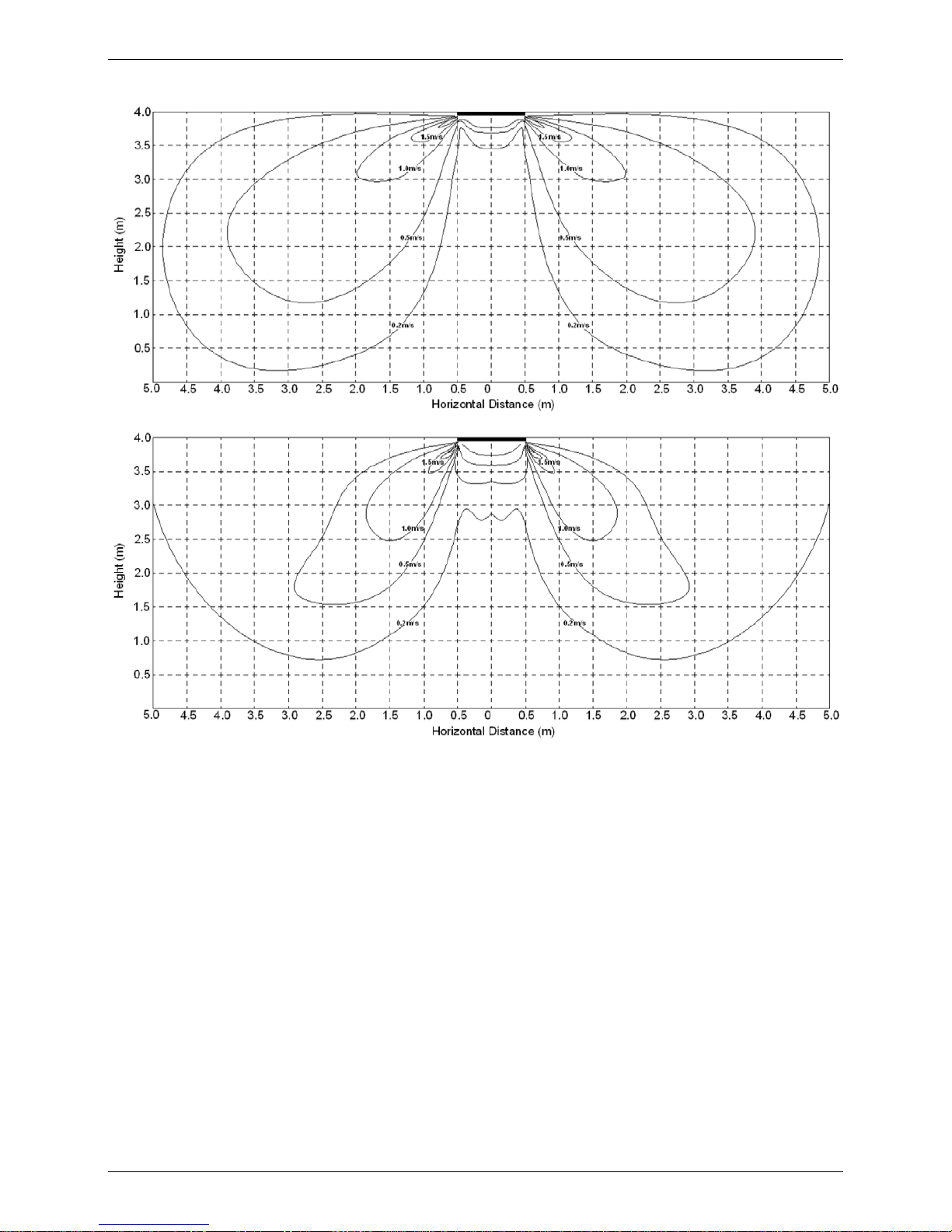
Floor installation:
Discharge angle 17°
Discharge angle 50°
Page 48

Air Velocity and Temperature Distributions (Reference Data)
46 Indoor Units
Model:
Ceiling installation:
Discharge angle 17°
Discharge angle 50°
FSPIF-480AE0,
FSPIF-601AE0
Page 49

Air Velocity and Temperature Distributions (Reference Data)
Indoor Units 47
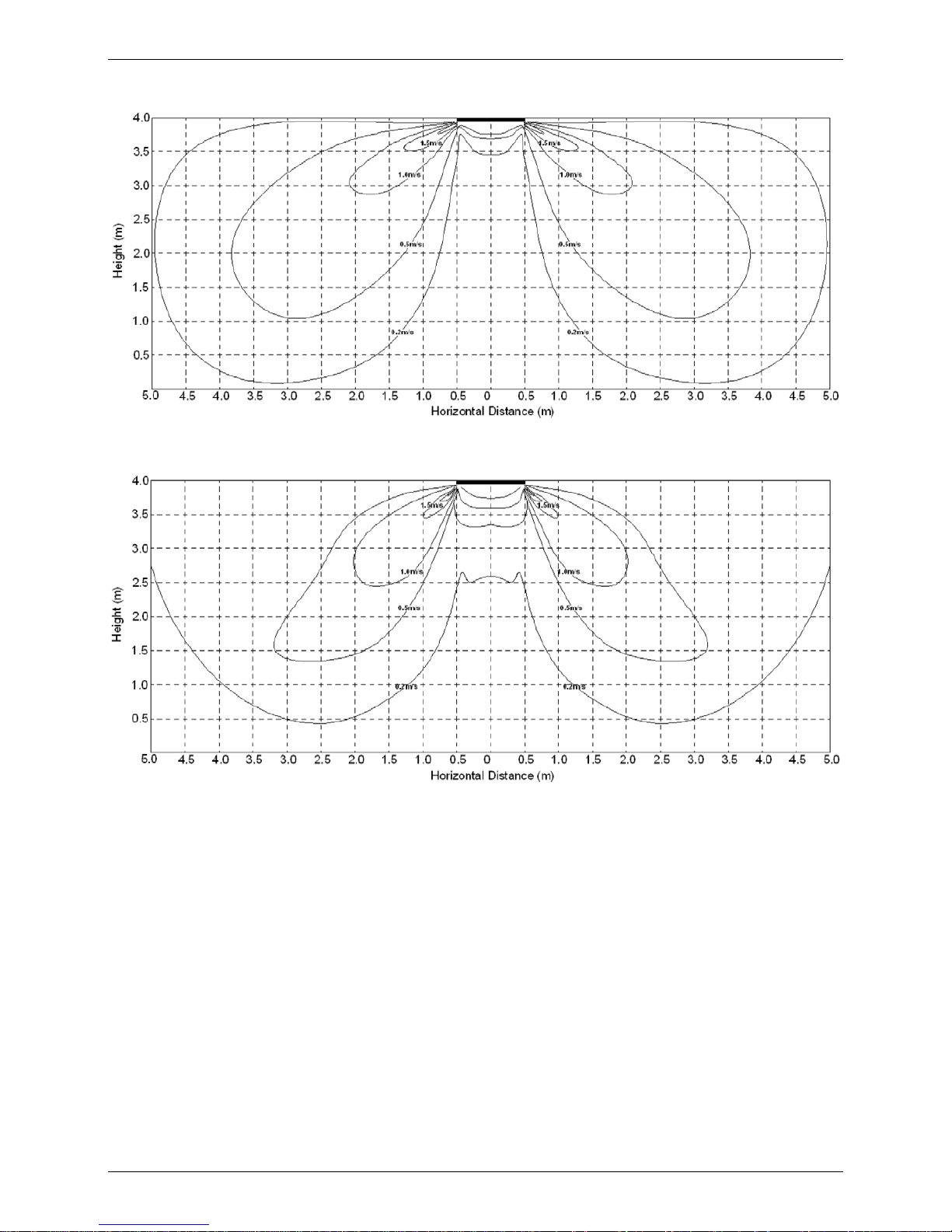
Floor installation:
Discharge angle 17°
Discharge angle 50°
Page 50

Accessories
48 Indoor Units
7. Accessories
Name Shape Quantity
Remote controller & Its
holder(The product you
have might not be
provided the following
accessories)
1. Remote controller 1
2. Remote controller holder 1
3. Mounting screw (ST2.9×10-C-H) 2
4. Alkaline dry batteries (AM4) 2
Others
5. Owner's manual
1
6. Installation manual
1
7. Remote controller manual
1
8. The Specification of Power
36000 Btu/h
INDOOR UNIT
POWER
Frequency and
Voltage
220-240V, 50Hz 220-240V, 50Hz 220-240V, 50Hz 220-240V, 50Hz
POWER WIRING
(mm2)
CIRCUIT BREAKER
/ Fuse (A)
15/10 15/10 15/10 15/10
OUTDOOR UNIT
POWER
Frequency and
Voltage
220-240V, 50Hz 220-240V, 50Hz 220-240V, 50Hz 380-420V, 50Hz
POWER WIRING
(mm2)
CIRCUIT BREAKER
/ Fuse (A)
Indoor/Outdoor Connecting Wiring
(Weak Electric Signal) (mm2)
2×0.2 (shielded)
Indoor/Outdoor Connecting Wiring
(Strong Electric Signal) (mm2)
30000 Btu/h
24000 Btu/h
Phase
1-phase
3-phase
1-phase
1-phase
1-phase
1-phase
Phase
3x2,5
3x4,0
5x2,5
3x1,5
3x1,5
3x1,5
20/16
30/25
3x 20/16
2×0.2 (shielded)
2×0.2 (shielded)
Model
18000 Btu/h
1-phase
3x1,5
1-phase
2×0.2 (shielded)
3x2,5
30/20
INDOOR UNIT
POWER
Frequency and
Voltage
Power Wiring
(mm
2
)
Circuit Breaker/Fuse
(A)
OUTDOOR UNIT
POWER
Frequency and
Voltage
Power Wiring
(mm
2
)
Circuit Breaker/Fuse
(A)
Indoor/Outdoor Connecting Wiring
(Weak Electric Signal) (mm
2
)
Indoor/Outdoor Connecting Wiring
(Strong Electric Signal) (mm2)
3-phase
48000 Btu/h
1-phase
380-420V, 50Hz
5x2,5
3x1,5
3x 20/16
2×0.2 (shielded)
Model
Phase
Phase
60000 Btu/h
1-phase
3-phase
380-420V, 50Hz
2×0.2 (shielded)
3x1,5
5x2,5
3x 30/20
15/10
220-240V, 50Hz
220-240V, 50Hz
15/10
Page 51

Wiring Diagram
Indoor Units 49
Field Wiring
9.
Page 52

Wiring Diagram
50 Indoor Units
10. Wiring diagram
FSPIF-181AE2
Page 53

Ceiling & Floor Type
Indoor Units 51
FSPIF-241AE2
FSPIF-301AE2
Page 54

Wiring Diagram
52 Indoor Units
FSPIF-362AE2
FSPIF-480AE0
FSPIF-601AE0
Page 55

Four-way Cassette Type (Compact)
Indoor Units 53
Four-way Cassette Type (Compact)
1. Features ............................................................................ 54
2. Dimensions ...................................................................... 55
3. Service Space .................................................................. 56
4. Air Velocity and Temperature Distributions
...............
57
5. Electric Characteristics .................................................. 58
6. Sound Levels ................................................................... 58
7. Accessories ..................................................................... 59
8. The Specification of Power ............................................ 59
9. Field Wiring ..................................................................... 60
10. Wiring diagram................................................................ 61
Page 56

Features
54 Indoor Units
1. Features
1.1 New panel
360°surrounding air outlet design, affords comfortable feeling
1.2 Compact design
The body size is 570×260×570mm, it’s just smaller than the ceiling board, so it’s very easy for
installation and will not damage the decoration. The panel size is 647×50×647mm.
The hooks are designed in the four corners of the body, which can save installation space.
1.3 Electric control box built-in design
The E-box is simply and safely built inside the indoor unit. It’s convenient for installation and
maintenance. Can check the control part easily, you only need to open the air return grille.
1.4 Air passage function
Reserves the space for air outlet from the side of indoor unit; It’s availed to connect air duct
from the two sides to the nearby small rooms.
Page 57

Dimensions
Indoor Units 55
2. Dimensions
Panel
Gas side
Liquid side
4-install hanger
Body
Drain pipe32
Fresh air intake
65
647
647
50
Drain hole
( for Service )
545
570
260
68
42
157
126
44
Wiring connection port
75
150
Distribution duct
2-
E-parts box
4-Screw hole
(for install panel)
523
570
Wiring connection port
170
2-
FSKIF-121AE2-EU
FSKIF-184AE2-EU
Page 58

Service Space
56 Indoor Units
3. Service Space
Page 59

Air Velocity and Temperature Distributions (Reference Data)
Indoor Units 57
4. Air Velocity and Temperature Distribution
s (Reference Data)
A irflo w velo city
Tem perature
Page 60

Electric Characteristics
58 Indoor Units
5. Electric Characteristics
Model
Indoor Units Power Supply
Hz Voltage Min. Max. MFA
Note:
MFA: Max. Fuse Amps. (A)
6. Sound Levels
1.4m
Microphone
Model Noise Power dB(A)
Noise level dB(A)
H M L
FSKIF-121AE2-EU
FSKIF-184AE2-EU
50
220-240 198
254
10
50
220-240 198
254
10
57
56
42
38
34
46
42
38
FSKIF-121AE2-EU
FSKIF-184AE2-EU
Page 61

Accessories
Indoor Units 59
7. Accessories
Name Shape Quantity
Installation Fittings
Installation paper board
1
Tubing & Fittings
Soundproof / insulation sheath
1
Drainpipe Fittings
Out-let pipe sheath
1
Out-let pipe clasp 1
Drain joint 1
Seal ring 1
Remote controller & Its
Frame(The product you
have might not be
provided the following
accessories)
Remote controller & Its Frame
1
Remote controller holder 1
Mounting screw(ST2.9×10-C-H) 2
Remote controller manual 1
Alkaline dry batteries (AM4)
2
Others
Owner's manual 1
Installation manual 1
Installation accessory
(The product you have
might not be provided the
following accessories
Expansible hook
4
Installation hook
4
Orifice
1
8. The Specification of Power
MODEL 12000 Btu/h 18000 Btu/h
Power
Phase 1-phase 1-phase
Frequency and Voltage 220-240V, 50Hz 220-240V, 50Hz
Circuit Breaker/ Fuse (A)
Indoor Unit Power Wiring (mm2)
3x1.5
Indoor/Outdoor Connecting Wiring
(mm2)
Ground Wiring 2.5 2.5
Outdoor Unit Power
Wiring
3×2.5 3×2.5
Strong Electric Signal 4×1.5
Weak Electric Signal 2×0.2
20/16
20/16
shielded
Page 62

60 Indoor Units
9. Field Wiring
FSKIF-121AE2-EU
FSKIF-184AE2-EU
12k unit
Field Wiring
Page 63

Indoor Units 61
10.Wiring diagram
FSKIF-121AE2-EU
FSKIF-184AE2-EU
Wiring Diagram
Page 64

Console Type
Console Type
1. Features ............................................................................. 61
2. Dimensions ...................................................................... 63
3. Service Space .................................................................. 64
4. Air Velocity and Temperature Distributions................
65
5. Electric Characteristics .................................................. 66
6. Sound Levels ................................................................... 67
7. Accessories ..................................................................... 68
8. The Specification of Power ............................................ 68
9. Field Wiring ..................................................................... 69
10. Field Wiring ................................................................... 70
60 Indoor Units
Page 65

Features
1. Features
1.1. Modern and elegant appearance
The simple and stylish designs can nicely harmonies with your living space.
1.3. Two air-outlet ways
Cooling mode
Quick Cooling To maintain room temp
Air outlet from top and bottom to make quick cooling ------When the A/C is just switched on, or room
temp. is still high, cold air will be blown out from top and bottom air outlet to cool down the room quickly
Air outlet from top to maintain room temp. ----When the room has been cooled down, or the A/C has
been opened over 1 hour, cold air only from the top outlet to keep constant room temp
Heating mode
Anti-cold air ------When the AC is just turn on, temperature of evaporator is very low, in this case, in
Indoor Units 61
Page 66

Console Type
order to prevent cold air direct blowing, only the upper louver is opened in a high position, the lower
louver closed.
1.4. Four air inlets
1.5. Low noise
DC indoor fan motor, which has five speeds.
Low noise and energy saving.
Advanced centrifugal fan technology makes a fast airflow and reduces the indoor noise.
1.6. Active carbon filter is standard.
62 Indoor Units
Page 67

Console Type
2. Dimensions
16 Drain pipe
195
Hanging arm
Unit: mm
700
600
210
Indoor Units 63
Page 68

Console Type
3. Service Space
64 Indoor Units
Page 69

Console Type
4. Air Velocity and Temperature Distributions (Reference Data)
Discharge angle 60
Airflow velocity
Temperature
Indoor Units 65
Page 70

Console Type
5. Electric Characteristics
Model
Indoor Units Power Supply
Hz Voltage Min. Max. MFA
50 220-240 198 254 16
66 Indoor Units
FSFIF-121AE2
Page 71

Console Type
6. Sound Levels
1.5m
1m
Microphone
Model
Noise Power
dB(A)
Noise level dB(A)
H M L
Indoor Units 67
FSFIF-121AE2
58
47
41
35
Page 72

Console Type
7. Accessories
Name Shape Quantity
Installation fittings Hook
2
Remote controller & Its Frame
Remote controller
1
Frame
1
Mounting screw(ST2.9×10-C-H)
2
Alkaline dry batteries (AM4)
2
Others
Installation manual / 1
Owner's manual / 1
8. The Specification of Power
MODEL 12000 Btu/h
Power
Phase 1-phase
Frequency and Voltage 220-240V, 50Hz
Circuit Breaker/ Fuse (A) 20/16
Indoor Unit Power Wiring (mm2)
Indoor/Outdoor Connecting Wiring
(mm2)
Ground Wiring 2.5
Outdoor Unit Power
Wiring
3×2.5
Strong Electric Signal 4×1.5
Weak Electric Signal
68 Indoor Units
Page 73

Console Type
9. Field Wiring
Indoor Units 69
FSFIF-121AE2
12
Page 74

Console Type
10. Wiring diagram
70 Indoor Units
FSFIF-121AE2
Page 75

Outdoor Units
Outdoor Units 71
Part 3
Outdoor Units
1. Dimensions ...................................................................... 73
2. .................................................................. 75
4. Electric Characteristics .................................................. 77
Sound Levels
.............................................................. 78
6.
...............................................................
79
7. Wiring Diagrams............................................................. 80
3. Pipingc Diagrams ............................................................
Service Space
76
5. Operation Limits
Page 76

Outdoor Units
72 Outdoor Units
Page 77

Dimensions
Outdoor Units 73
1. Dimensions
W
H
W1
A
B
D
Model(KBtu/h)
Unit:mm
W D H W1 A B
12/18
800 333 554 870 514 340
24
845 363 702 914 540 350
30/36
946 410 810 1030 673 403
Page 78

Dimensions
74 Outdoor Units
Model(KBtu/h)
Unit:mm
W D H W1 A B
48/60
952 415 1333 1045 634 404
Page 79

Service Space
Outdoor Units 75
2. Service Space
More than 60cm
More than 30cm
More than 60cm
More than 200cm
Air inlet
Air inlet
More than 30cm
Air outlet
(Wall or obstacle)
Maintain channel
Page 80

Piping Diagrams
76 Outdoor Units
3. Piping Diagrams
LIQUID SIDE
GAS SIDE
HEAT
EXCHANGE
(EVAPORATOR)
HEAT
EXCHANGE
(CONDENSER)
Compressor
2-WAY VALVE
3-WAY VALVE
4-WAY VALVE
COOLING
HEATING
T2B Evaporator
temp. sensor
outlet
T1 Room temp.
sensor
T3 Condenser
temp. sensor
T5 Discharge
temp. sensor
T4 Ambient
temp. sensor
INDOOR OUTDOOR
T2 Evaporator
temp. sensor
middle
Accumulator
Electronic
expansion valve
CAPILIARY TUBE
For FSOIF-243AE2, there is no accumulator.
LIQUID SIDE
GAS SIDE
HEAT
EXCHANGE
(EVAPORATOR)
HEAT
EXCHANGE
(CONDENSER)
Compressor
2-WAY VALVE
3-WAY VALVE
4-WAY VALVE
COOLING
HEATING
T2B Evaporator
temp. sensor
outlet
T1 Room temp.
sensor
T3 Condenser
temp. sensor
Accumulator
T5 Discharge tem p. sensor
High pressure switch
T4 Ambient
temp. sensor
Low pressure
switch
INDOOR OUTDOOR
Oil return Capillary
Oil separator
T2 Evaporator
temp. sensor
middle
Electronic
expansion valve
CAPILIARY TUBE
For FSOIF-301AE2, there are no oil separator and oil return capillary.
FSOIF-121AE2
FSOIF-183AE2
FSOIF-243AE2
FSOIF-362AE2-3F
FSOIF-482AE0-3F
FSOIF-602AE0-3F
FSOIF-301AE2
Page 81

Electric
Characteristics
Outdoor Units 77
4. Electric Characteristics
Model
Outdoor Unit
Hz Voltage Min. Max.
FSOIF-362AE2-3F
FSOIF-482AE0-3F
FSOIF-602AE0-3F
FSOIF-301AE2
FSOIF-121AE2
FSOIF-183AE2
FSOIF-243AE2
50
220-240V
198V
254V
50
220-240V
198V
254V
50
220-240V
198V
254V
50
220-240V
198V
254V
50
380-415V
342V
400V
50
380-415V
342V
400V
50
380-415V
342V
400V
Page 82

Operation Limits
78 Outdoor Units
5. Operation Limits
Temperature
Mode
Cooling operation Heating operation Drying operation
Room temperature
17℃~32℃ 0℃~30℃ 17℃~32℃
Outdoor temperature
-15℃~24℃ 0℃~50℃
-15℃~50℃
CAUTION:
1. If the air conditioner is used beyond the above conditions, certain safety protection features may come
into operation and cause the unit to operate abnormally.
2. The room relative humidity should be less than 80%. If the air conditioner operates beyond this figure, the
surface of the air conditioner may attract condensation. Please set the vertical air flow louver to its maximum
angle (vertically to the floor), and set HIGH fan mode.
3. The optimum performance will be achieved during this operating temperature zone.
Page 83

Sound Levels
Outdoor Units 79
6. Sound Levels
H
1.0m
Outdoor Unit
Microphone
Note: H= 0.5 × height of outdoor unit
Model Noise Power dB(A) Noise level dB(A)
FSOIF-362AE2-3F
FSOIF-482AE0-3F
FSOIF-602AE0-3F
FSOIF-301AE2
FSOIF-121AE2
FSOIF-183AE2
FSOIF-243AE2
60
64
65
67
67
72
74
57
56,5
60,5
59,5
62
65
62,5
Page 84

Wiring diagram
80 Outdoor Units
7. Wiring diagram
FSOIF-121AE2
FSOIF-183AE2
Page 85

Wiring diagram
Outdoor Units 81
FSOIF-301AE2
FSOIF-243AE2
FSOIF-362AE2-3F
Page 86

Wiring diagram
82 Outdoor Units
FSOIF-482AE0-3F
FSOIF-602AE0-3F
Page 87

Wiring diagram
Outdoor Units 83
Page 88

Installation
84 Installation
Part 4
Installation
1. Installation Procedure ................................................... 85
2. Location selection ......................................................... 86
3. Indoor unit installation .................................................. 87
4. Outdoor unit installation (Side Discharge Unit) .......... 102
5. Refrigerant pipe installation ......................................... 103
6. Drainage pipe installation ............................................. 107
7. Vacuum Drying and Leakage Checking ...................... 111
8. Additional refrigerant charge ....................................... 112
9. Engineering of insulation ............................................. 113
10. Engineering of electrical wiring ................................... 114
11. Test operation ................................................................115
Page 89

Installation Procedure
Installation 85
1. Installation Procedure
Vacuum drying and leakage checking
Additional refrigerant charge
Insulation the joint part of refrigerant pipe
Wiring connection and electric safety checking
Test operation
Refrigerant pipe
installation and insulation
Drainage pipe installation
and insulation
Indoor unit installation
location selection
Outdoor unit installation
location selection
Indoor unit installation Outdoor unit installation
Refrigerant pipe
installation and insulation
Drainage pipe installation
and insulation
Page 90

Location selection
86 Installation
2. Location selection
2.1 Indoor unit location selection
The place shall easily support the indoor unit’s weight.
The place can ensure the indoor unit installation and inspection.
The place can ensure the indoor unit horizontally installed.
The place shall allow easy water drainage.
The place shall easily connect with the outdoor unit.
The place where air circulation in the room should be good.
There should not be any heat source or steam near the unit.
There should not be any oil gas near the unit
There should not be any corrosive gas near the unit
There should not be any salty air neat the unit
There should not be strong electromagnetic wave near the unit
There should not be inflammable materials or gas near the unit
There should not be strong voltage vibration.
2.2 Outdoor unit location selection
The place shall easily support the outdoor unit’s weight.
Locate the outdoor unit as close to indoor unit as possible
The piping length and height drop can not exceed the allowable value.
The place where the noise, vibration and outlet air do not disturb the neighbors.
There is enough room for installation and maintenance.
The air outlet and the air inlet are not impeded, and not face the strong wind.
It is easy to install the connecting pipes and cables.
There is no danger of fire due to leakage of inflammable gas.
It should be a dry and well ventilation place
The support should be flat and horizontal
Do not install the outdoor unit in a dirty or severely polluted place, so as to avoid blockage of the heat
exchanger in the outdoor unit.
If is built over the unit to prevent direct sunlight, rain exposure, direct strong wend, snow and other scraps
accumulation, make sure that heat radiation from the condenser is not restricted.
More than 30cm
More than 60cm
More than 200cm
More than 30cm
More than 60cm
(Service space
︶
F
e
n
c
e
o
r
o
b
s
t
a
c
l
e
s
Page 91

Indoor unit installation
Installation 87
3. Indoor unit installation
3.1 Super slim cassette indoor unit installation
3.1.1 Service space for indoor unit
Model A H
24/30/36
245 >275
48/60 287 >317
3.1.2 Bolt pitch
3.1.3 Install the pendant bolt
Select the position of installation hooks according to the hook holes positions showed in upper picture.
Drill four holes of Ø12mm, 45~50mm deep at the selected positions on the ceiling. Then embed the
expansible hooks (fittings).
Page 92

Indoor unit installation
88 Installation
3.1.4 Install the main body
Make the 4 suspender through the 4 hanger of the main body to suspend it. Adjust the hexangular nuts on
the four installation hooks evenly, to ensure the balance of the body. Use a leveling instrument to make sure
the levelness of the main body is within ±1°.
Adjust the position to ensure the gaps between the body and the four sides of ceiling are even. The body's
lower part should sink into the ceiling for 10~12 mm. In general, L is half of the screw length of the
installation hook.
Locate the air conditioner firmly by wrenching the nuts after having adjusted the body's position well.
3.1.5 Install the panel
Remove the grille
Page 93

Indoor unit installation
Installation 89
Remove the 4 corner covers.
Hang the panel to the hooks on the mainbody. If the panel is with auto-lift grille, please watch the ropes lifing
the grille, DO NOT make the ropes enwinded or blocked.
Tighten the screws under the panel hooks till the panel closely stick on the ceiling to avoid condensate
water.
Page 94

Indoor unit installation
90 Installation
Hang the air-in grill to the panel, then connect the lead terminator of the swing motor and that of the control
box with corresponding terminators on the body respectively.
Install the 4 corner covers back.
Note: The panel shall be installed after the wiring connected.
Page 95

Indoor unit installation
Installation 91
3.2 Duct indoor unit installation
3.2.1 Service space for indoor unit
3.2.2 Bolt pitch
Capacity(KBtu)
Size of outline dimension mounted plug
L M
18/24 960 350
30 1240 500
36~60 1240 500
3.2.3 Install the pendant bolt
Select the position of installation hooks according to the hook holes positions showed in upper picture.
Drill four holes of Ø12mm, 45~50mm deep at the selected positions on the ceiling. Then embed the
expansible hooks (fittings).
Page 96

Indoor unit installation
92 Installation
3.2.4 Install the main body
Make the 4 suspender through the 4 hanger of the main body to suspend it. Adjust the hexangular nuts on
the four installation hooks evenly, to ensure the balance of the body. Use a leveling instrument to make sure
the levelness of the main body is within ±1°.
3.2.5 Install the air filter
Insert the air filter through the filter slot and fix it with 2 screws.
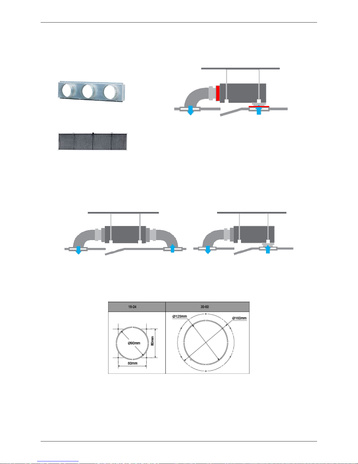
3.2.6 Install the air duct
Please design the air duct as below recommended picture
Page 97

Indoor unit installation
Installation 93
3.2.7 Change the air inlet direction
① Take off ventilation panel and flange, cut off the staples at side rail.
② Stick the attached seal sponge as per the indicating place in the following fig, and then change the
mounting positions of air return panel and air return flange .
③ When install the filter mesh, please plug it into flange inclined from air return opening, and then push up.
④ The installation has finish, upon filter mesh which fixing blocks have been insert to the flange positional
holes.
Page 98

Indoor unit installation
94 Installation
3.3 Ceiling & floor indoor unit installation
3.3.1 Service space for indoor unit
3.3.2 Bolt pitch
① Ceiling installation
Capacity (KBtu/h)
D E
18/24 983 220
30K 1200 220
36~60 1565 220
② Wall-mounted installation
3.3.3 Install the pendant bolt
① Ceiling installation
Select the position of installation hooks according to the hook holes positions showed in upper picture.
Page 99

Indoor unit installation
Installation 95
Drill four holes of Ø12mm, 45~50mm deep at the selected positions on the ceiling. Then embed the
expansible hooks (fittings).
② Wall-mounted installation
Install the tapping screws onto the wall.(Refer to picture below)
3.3.4 Install the main body
① Ceiling installation (The only installation method for the unit with drain pump)
Remove the side board and the grille.
Locate the hanging arm on the hanging screw bolt. Prepare the mounting bolts on the unit.
Page 100

Indoor unit installation
96 Installation
Put the side panels and grilles back.
② Wall-mounted installation
Hang the indoor unit by insert the tapping screws into the hanging arms on the main unit. (The bottom of
body can touch with floor or suspended, but the body must install vertically.)
 Loading...