

Page 1

Instruction Manual
D103466X012
HPNS Valve
March 2022
Fisher
™
HPNS Control Valve
Contents
Introduction 1.................................
Scope of Manual 1.............................
Description 1.................................
Specifications 2...............................
Educational Services 2.........................
Principle of Operation 4.........................
Lifting Guidelines 5.............................
Installation 6..................................
Maintenance 8.................................
Bonnet Nut Torquing Considerations 9...........
Packing Lubrication 10.........................
Packing Maintenance 10........................
Replacing Conventional Packing 11...........
Replacing HIGH-SEAL Packing 17.............
Trim Removal 18..............................
Standard Balanced and Unbalanced
Trim Removal 18........................
Bore Seal Trim Removal 18..................
Trim Replacement 19..........................
Installing Dynamic Bore Seal Trim 23.............
Installing Static Bore Seal Trim 26................
Hermetically Sealed Bellows Valve 28..............
Packing Maintenance 28........................
Replacement of an Installed Bellow Seal 28........
Trim Removal 31..............................
Figure 1. HPNS Valve with 667NS2 Actuator
Trim Replacement 31..........................
Troubleshooting 40.............................
Parts Ordering 41...............................
Parts List 41...................................
Introduction
Scope of Manual
This instruction manual includes installation, maintenance, and parts information for NPS 1/2 through NPS 10 HPNS
valves with CL900 through CL2075 ratings. Note: Applications requiring lower pressure class ratings may use the same
casting as a higher rated valve of the required size. Refer to separate manuals for instructions covering the actuator,
positioner, and accessories.
Do not install, operate, or maintain HPNS valves without being fully trained and qualified in valve,
actuator, and accessory installation, operation, and maintenance. To avoid personal injury or property
damage, it is important to carefully read, understand, and follow all the contents of this manual,
including all safety cautions and warnings. If you have any questions about these instructions, contact
your Emerson sales office
Description
HPNS valves (figure 1) have buttweld end connections in various schedules and are designed for use with Fisher
667NS2 and 657NS2 actuators and can also be used with a Fisher yoke and other piston actuator options. HPNS valves
are designed to handle high seismic environments.
before proceeding.
www.Fisher.com
Page 2

HPNS Valve
March 2022
Table 1. Specifications
Instruction Manual
D103466X012
End Connection Styles and Ratings
(1,2)
Buttwelding: Consistent with Schedule 40-160
Flanges: Not available
Socket Welding: Not available
Also see table 2
Shutoff Classifications
See table 3
Bidirectional Trim: Class V. See table 4
Bore Seal trim: High‐temperature, Class IV and V.
See table 4
Flow Characteristic
Standard Cage: J Equal percentage, J Modified
equal percentage, J Linear or, J Quick opening
on/off
Micro‐Form Valve Plug: J Equal percentage
J Modified equal percentage or, J Quick opening
on/off
Flow Direction
Standard Cage
J HPNS Balanced: Normally flow up
J HPNS Unbalanced: Normally flow down or up
(3)
(4)
Cavitrol III Cage: Flow down
Whisper Trim III Cage: Flow up
Approximate Weights
(valve body and bonnet assemblies)
See table 2
Bolt Torque Tolerance
Torque values given are +/- 5%, unless otherwise
specified
Special Tools
Standard mechanics tools are used for
assembly/disassembly, except for:
Valves supplied with bore seal plugs:
J a bore seal installation tool is required for proper
installation of the bore seal (see figure 13 for dynamic
bore seal and figure 16 for static bore seal),
J a center punch is also used to stake the bore seal
retainer threads after installation, J a 1/8 inch
diameter drill bit is recommended for removing the
deformed section of thread on the bore seal retainer
during bore seal replacement
Valves supplied with hermetically-sealed bellows
seal:
J a loading fixture is required for performing
seal-weld between bellows flange and valve body (see
figure 19)
Cavitrolt III or Whisper Trimt III Cage: J Linear
Additional Specifications
For specifications such as materials, valve plug
Special cages: Special characterized flow cages are
available. Consult your Emerson sales office
1. EN (or other) ratings and other BWE can usually be supplied; consult your Emerson sales office.
2. The pressure or temperature limits in this manual and any applicable standard limitations should not be exceeded.
3. HPNS Balanced valves may be used flow down where required by design.
4. HPNS Unbalanced valves may be used flow down for on‐off service or where required by design.
travels, and port, yoke bolt circle, and stem
diameters, see the Parts List section
Specifications
Specifications for the HPNS valves are shown in table 1.
Educational Services
For information on available courses for the Fisher HPNS valve, as well as a variety of other products, contact:
Emerson Automation Solutions
Educational Services - Registration
Phone: 1-641-754-3771 or 1-800-338-8158
E-mail: education@emerson.com
emerson.com/fishervalvetraining
2
Page 3

Instruction Manual
D103466X012
Table 2. Valve Assembly Approximate Weights
VALVE SIZE, NPS PRESSURE RATING KG LBS
1/2
1 117 257
2 118 259
3 271 596
4
6 374 823
8
10 2064 4550
Table 3. Shutoff Classifications per ANSI/FCI 70‐2 and IEC 60534‐4
VALVE DESIGN VALVE SIZE, NPS
1/2 6.35 (0.25) Micro-Form V
1
Unbalanced HPNS
2
3 73.03 (2.875) Linear (std. cage) V
2075
900
1725
PORT DIAMETER,
mm (INCHES)
6.35 (0.25) to 25.4 (1) Micro-Form
25.4 (1) Micro-Form
25.4 (1) Special (Cavitrol III, 3-stage)
47.63 (1.875)
47.63 (1.875) Linear
136 300
261 574
940 2071
TRIM STYLE LEAKAGE CLASS
IV (forward)
V (reverse)
Equal %
(std or Whisper III, B3 cage)
Linear
(std or Whisper III, B3 cage)
IV (forward)
V (reverse)
HPNS Valve
March 2022
IV
V
V
Table 4. Additional Shutoff Classification per ANSI/FCI 70‐2 and IEC 60534‐4
VALVE DESIGN VALVE SIZE, NPS
3 73.0 (2.875)
4 92.1 (3.625) Modified Equal %
5 136.525 (5.375) Linear (std. cage)
Balanced HPNS
6
8
10 254 (10) Linear
PORT DIAMETER,
mm (INCHES)
Linear (Whisper III, C3) V
136.525 (5.375) Linear (std. cage) IV
133.35 (5.25) Special (Cavitrol III, 2-stage)
177.8 (7) Linear (std. cage)
111.125 (4.375) Special IV Bidirectional
CAGE STYLE LEAKAGE CLASS
Equal % III
IV
V
IV
V
V (forward)
IV (reverse)
IV
V
V (forward)
IV (reverse)
3
Page 4

HPNS Valve
March 2022
Instruction Manual
Table 5. Torque for Body‐to‐Bonnet Bolting Using Nuclear Grade Anti-Seize Lubricant
VALVE
SIZE,
NPS
1/2 676 711 818 498 524 603
1 883 929 1068 651 685 788
2 883 929 1068 651 685 788
3 1648 1735 1995 1216 1280 1472
4 1230 1295 1489 907 955 1098
6 2164 2278 2620 1596 1680 1932
8 4315 4542 5223 3183 3350 3853
10 10420 10968 12613 7686 8090 9304
Minimum Nominal Maximum Minimum Nominal Maximum
NSm lbfSft
TORQUE
Table 6. Recommended Torque for Packing Flange Nuts (non live‐loaded)
STEM
DIAMETER
mm Inches Min Max Min Max
12.7 0.5
19.05 0.75
25.4 1 600 34 50 25 37
CLASS
150 5 8 4 6
900 12 18 9 13
1500 18 24 13 18
1500 18 24 13 18
2075 41 61 30 45
NSm lbfSft
TORQUE
D103466X012
Principle of Operation
HPNS valves are control valves based on the Fisher HP valve product. The valve body and bonnet contain a fluid under
pressure, while the internal valve parts control the flow of the fluid through the valve. The internal parts consist of
gaskets, a seat ring, a plugstem assembly, and a cage. Additional seals might be used depending on the exact
function and design of the valve.
The gaskets, seat ring, and cage are stationary and held in place inside the valve body and bonnet by the force applied
by the body-to-bonnet bolting. The plugstem assembly is designed to move up and down (axially) inside the cage.
The stem passes through a hole in the bonnet, and can be moved up and down (axially) by an external actuator
attached to the valve body, or bonnet. Sealing packing is used between the valve bonnet and plug stem to prevent the
fluid from leaking out of the valve, while still allowing the plug stem to move axially.
Fluid enters one end of the valve. When the stem is pushed down, the plug moves to contact the seat ring, and
“closes” the valve, preventing the fluid from passing through the valve. When the stem is pulled up, the plug
disengages from the seat ring, and slides up through the center of the cage, exposing holes or flow passages in the
cage. This allows the fluid to flow through seat ring and cage, and exit the valve through the opposite end of the valve
which it entered. By positioning the plug at different "travels" in the cage, the amount of flow through the valve can be
controlled.
4
Page 5

Instruction Manual
D103466X012
HPNS Valve
March 2022
Lifting Guidelines
WARNING
Failure to follow these lifting guidelines and accepted lifting and rigging practices could result in property damage and
personal injury or death.
All lifting and rigging must be completed in accordance with federal/national/provincial, state and local regulations and
applicable lifting and rigging equipment standards. Only personnel trained in proper lifting and rigging practices shall
perform valve/actuator assembly lifting, rigging and installation. Because each lift will be unique, the method of lifting the
valve assembly, the correct location for attaching and lifting the valve assembly, and what the valve assembly will do when
lifted shall be considered for each lift.
Lifting and rigging equipment used to lift, install or remove a valve assembly or component must be properly selected and
sized for the weight and configuration of the valve assembly or component being lifted. The weight of the complete valve
assembly, including attached accessories, must be taken in consideration for this purpose. The lifting and rigging
equipment must be properly maintained and inspected for damage before each use.
If the valve is supplied with an actuator or handwheel, do not use the actuator or handwheel to lift the complete valve
assembly. Lifting lugs attached to the actuator must not be used to lift the complete valve assembly unless clearly marked
as being rated to support the complete valve assembly weight.
Lifting lugs or other lifting equipment attached to the valve or actuator must never be used to lift or support the weight of
attached piping.
CAUTION
Care must be taken when lifting the valve/actuator assembly to ensure all accessories and tubing are not damaged in the
process. Accessories and tubing may need to be removed prior to lifting to prevent damage and properly reinstalled before
use. Protect valve flange faces, butt weld ends, and other connection surfaces from damage during lifting.
The quantity of eyebolts for lifting purpose is the minimum recommendation. More eyebolts can be used per customer
experience. When tightening the eyebolts and nuts, do not exceed the torque that is specified on the diaphragm casing cap
screws and nuts (keys 119 and 120) in the following sections, to avoid damage on the diaphragm.
Lifting Valve/Actuator Assembly
To lift the valve/actuator assembly, eyebolts should be used. Insert four 3/8 inch shouldered pattern eyebolts
positioned 90 degrees apart on the diaphragm casing flange for size 45 and 70. Use six 7/16 inch shouldered pattern
eyebolts positioned 60 degrees apart on the diaphragm casing flange for size 80. Two nuts are required with one on
each side of the diaphragm casing flange. A longer strap is recommended, so that the angle between the straps
connecting each eyebolt can be smaller, which helps the eyebolts hold more weight. The eyebolt should be ASTM
A489-K04800 or stronger material.
For a bellows seal valve, the valve/actuator assembly should be lifted using one or more lifting straps that are rigged to
choke around the actuator under the diaphragm casing. Use protective pads between the strap(s) and casing to help
prevent damage to the painted surface. A single hoist lift point on the strap(s) will balance and lift the valve/actuator
assembly in a level manner. If necessary, use additional slings around the valve inlet and outlet or around actuator legs
for body stabilization.
Lifting Valve Only
To lift the valve, eyebolts should be used. Insert 3/4-10 inch shouldered pattern eyebolts into two threaded holes
located on the top of the NPS 1/2 through NPS 6 valve bodies, positioned 180 degrees apart. For NPS 8 and NPS 10
valve bodies, insert two 3/4-10 shouldered pattern eyebolts into two threaded holes located on the top of the bonnet,
positioned 180 degrees apart. The eyebolt material should be ASTM A489-K04800 or stronger material. Be sure at
least 90% of the threads are engaged in the receiving hole, with a minimum thread engagement of at least 1-1/2 times
the thread diameter in steel. If necessary, place lifting slings around the inlet and outlet of the valve body for
stabilization. Use padding as needed to protect any painted surfaces. The valve can now be lifted using a hoist capable
of leveling the lifting points.
5
Page 6

HPNS Valve
March 2022
Instruction Manual
D103466X012
Lifting Actuator Only
To lift the actuator and accessories, eyebolts should be used. Insert two 3/8 inch shouldered pattern eyebolts
positioned 180 degrees apart on the diaphragm casing flange for size 45 and 70. Use four 7/16 inch shouldered
pattern eyebolts positioned 90 degrees apart on the diaphragm casing flange for size 80. Two nuts are required with
one on each side of the diaphragm casing flange. The eyebolt material should be ASTM A489-K04800 or stronger
material. For a bellows seal valve, the actuator should be lifted using one or more lifting straps that are rigged to choke
around the actuator under the diaphragm casing. Use protective pads between the strap(s) and casing to help prevent
damage to the painted surface. A single hoist lift point on the strap(s) will balance and lift the actuator in a level
manner.
Installation
When welding buttweld end valves in line, the control valve trim needs to be removed in order to prevent damage to
trim parts. The control trim also needs to be replaced with temporary sacrificial trim to be used while conducting the
system hydrostatic test and while flushing the system. Flushing the system helps to remove weld slag, rust, corrosion,
etc. that could otherwise flow through the valve and potentially damage valve seating surfaces or plug drilled hole
trims. The following installation description includes procedures and suggestions to follow for the flushing of the
system.
For the NPS 1/2 HPNS with hermetically sealed bellows (DS150), the trim should not be removed during assembly. The
position of the plug should be in the “up” position off the seat, with the bellows in the relaxed state. Because the
bellows flange is welded directly to the body, it should not be removed until the recommended replacement period,
see table 12.
WARNING
Always wear protective gloves, clothing, and eyewear when performing any installation operations to avoid personal
injury.
Personal injury or equipment damage caused by sudden release of pressure may result if the valve assembly is installed
where service conditions could exceed the limits given in table 1 or on the appropriate nameplates. To avoid such injury or
damage, provide a relief valve for over‐pressure protection as required by government or accepted industry codes and
good engineering practices.
Check with your process or safety engineer for any additional measures that must be taken to protect against process
media.
If installing into an existing application, also refer to the WARNING at the beginning of the Maintenance section in this
instruction manual.
WARNING
The valve configuration and construction materials were selected to meet particular pressure, temperature, pressure drop,
and controlled fluid conditions indicated when the valve was ordered. Responsibility for the safety of process media and
compatibility of valve materials with process media rests solely with the purchaser and end‐user. To avoid possible
personal injury and because some valve/trim material combinations are limited in their pressure drop and temperature
ranges, do not apply any other conditions to the valve without first contacting your Emerson sales office
.
WARNING
Some bonnet flanges have a tapped hole that was used to handle the bonnet during manufacture. Do not use this tapped
hole to lift the valve assembly or personal injury may result.
6
Page 7

Instruction Manual
D103466X012
HPNS Valve
March 2022
WARNING
If you are hoisting the valve, use lifting slings to protect the surfaces. Carefully position the slings to prevent damage to the
actuator tubing and any accessories. Also, take care to prevent people from being injured in case the hoist or rigging slips
unexpectedly. Refer to table 2 for valve assembly weights. It is important to use adequately sized hoists and chains or slings
when handling the valve.
1. Remove the actuator and disassemble the valve body by completing steps 1 through 10 of the Replacing
Conventional Packing section.
2. Before installing the valve, inspect it to ensure that the valve body cavity is free of foreign material.
3. Clean out all pipelines to remove scale, welding slag, and other foreign materials before installing the valve.
Note
If the valve body being installed has small internal flow passages, such as with Whisper Trim III or Cavitrol III cages, consideration
should be given to installing an upstream strainer to prevent the lodging of particles in these passages. This is especially important
if the pipeline cannot be thoroughly cleaned or if the flowing medium is not clean.
4. Flow through the valve must be in the direction indicated by the flow arrow, which is stamped on or attached to the
valve body.
CAUTION
Depending on valve body materials used, post‐weld heat treating might be needed. Post‐weld heat treatment can damage
internal elastomeric, plastic, and metal parts. Shrink‐fit pieces and threaded connections might also loosen. In general, if
post‐weld heat treating is needed, remove all trim parts. Contact your Emerson sales office for additional information.
5. Install the valve in the line. Use accepted piping and welding practices when installing the valve in the pipeline.
6. Install a three‐valve bypass around the valve if continuous operation is required during maintenance.
7. After installing the valve, inspect it once again to ensure that the valve body cavity is free and clear of foreign
material to avoid damaging any internals during flushing.
8. If the actuator and valve body are shipped separately, refer to the actuator mounting procedure in the appropriate
actuator instruction manual.
9. If the valve body was shipped without packing installed in the packing box, install the packing
valve body or putting the valve into service
. Refer to instructions given in the Packing Maintenance procedure.
10. For valves that are not being flushed, a replacement soft kit is needed because the trim is removed while the valve is
installed. The new soft kit is then used during valve assembly after installation.
11. For valves that will be flushed, some valves are designed such that no damage to internals is expected if the
standard valve trim parts are used during flushing. However, it is recommended that that the soft parts (packing
and gaskets) be replaced after flushing. Other valves are designed so that the trim can be removed and the valve
assembled with a “flushing stem.” Lastly, other valves will require a full flushing trim to be installed instead of the
standard trim. Valves using trim with hard-facing and valves using trim with small drilled holes or a small flow path
where particulate up to 1/4 inch can become lodged will require flushing trim. Table 7 details which special trim
parts are needed based on flow direction.
before flushing the
7
Page 8

HPNS Valve
March 2022
Instruction Manual
D103466X012
Table 7. Required Flushing Trim Items
FLOW CONDITION PARTS
Flow Up Soft Parts, Flushing System, and Flushing Nuts
Flow Down
1. For those datasheets that require only a flushing stem and flushing nuts, install the bonnet gasket. Refer to figure 26 for assemblies that do not require a flushing cage or flushing seat ring.
(1)
Soft Parts, Flushing System, Flushing Nuts, Flushing Cage and Flushing Seat
Ring
a. After installing the bonnet gasket, tighten 2 of the 4 flushing nuts to the base of the flushing stem. When
installing the nuts, ensure that the flat side of the upper nut (the side closest to the bonnet) is facing the bonnet
and that any of the grade markings are facing away from potentially contacting the bonnet.
b. Insert the flushing stem up through the bonnet (key 10), being careful not to scratch or otherwise damage the
stem.
c. Install new packing and the metal packing box parts according to steps 19 and 20 of the Replacing Conventional
Packing Section. If working on a valve with HIGHSEAL Packing, follow steps 2 through 7 of the HighSeal packing
installation section. At this point, do not tighten the packing bolts down.
d. Tighten the other two leftover flushing nuts to the top of the stem to secure the stem in position with the
bonnet.
e. Following step 17 of the Replacing Conventional Packing Section, place the bonnet on to the studs (key 7),
taking care to ensure that while moving the bonnet the flushing stem does not slide around and become
damaged.
f. Follow step 18 of the Replacing Conventional Packing Section to torque the bonnet into place. Because the stem
is not connected to the rest of the trim, the note about stroking the valve to center the trim can be omitted.
g. Now torque the packing bolts per table 6 if using conventional packing or step 8 of the HIGHSEAL Packing
Installation Section.
h. For those datasheets that require a full flushing trim, follow step 16 of the Replacing Conventional Packing
section up to the installation of the bonnet gasket (key 6), ensuring that the standard seat ring and standard
cage are replaced with the appropriate flushing cage and flushing seat ring. Then, follow the assembly directions
shown above for the installation of the flushing stem and nuts.
12. After system flushing is completed, remove the bonnet (key 10), bonnet gasket (key 6), and, if necessary, flushing
trim and seat ring gasket (key 5).
13. Assemble the valve as described in the Replacing Conventional Packing procedure, steps 11 through 20.
14. Refer to the actuator mounting procedure in the appropriate actuator instruction manual.
WARNING
Personal injury could result from packing leakage. Valve packing was tightened before shipment; however, the packing
might require some readjustment to meet specific service conditions. Please read and follow the packing adjustment
procedures in the Packing Maintenance section of this manual.
Valves with HIGH‐SEAL Heavy‐Duty live‐loaded packing will not require this initial re‐adjustment. See the Replacing
HIGH‐SEAL Packing section in this manual for packing instructions.
Maintenance
Valve parts are subject to normal wear and must be inspected and replaced as necessary. Inspection and maintenance
frequency depends on the severity of service conditions. This section includes instructions for packing maintenance
and trim maintenance. All maintenance operations may be performed with the valve in the line.
8
Page 9

Instruction Manual
D103466X012
HPNS Valve
March 2022
WARNING
Avoid personal injury or damage to property from sudden release of pressure or uncontrolled process fluid. Before starting
disassembly:
D Do not remove the actuator from the valve while the valve is still pressurized.
D Always wear protective gloves, clothing, and eyewear when performing any maintenance operations to avoid personal
injury.
D Disconnect any operating lines providing air pressure, electric power, or a control signal to the actuator. Be sure the
actuator cannot suddenly open or close the valve.
D Use bypass valves or completely shut off the process to isolate the valve from process pressure. Relieve process pressure
on both sides of the valve. Drain the process media from both sides of the valve.
D Vent the power actuator loading pressure and relieve any actuator spring precompression.
D Use lock‐out procedures to be sure that the above measures stay in effect while you work on the equipment.
D The valve packing box may contain process fluids that are pressurized, even when the valve has been removed from the
pipeline. Process fluids may spray out under pressure when removing the packing hardware or packing rings.
D Check with your process or safety engineer for any additional measures that must be taken to protect against process
media.
Note
The HPNS valve uses spiral‐wound gaskets which are crushed to provide their seal. A spiral‐wound gasket should never be reused.
Whenever a gasket seal is disturbed by removing or shifting gasketed parts, a new gasket must be installed upon reassembly. This
is necessary to ensure a good gasket seal, since the used gasket will not seal properly.
CAUTION
The spiral‐wound gaskets are of special design. Failure to use Fisher replacement parts may result in valve damage.
Note
If the valve has HIGH‐SEAL Heavy‐Duty live‐loaded packing installed (figure 4 or 5), see the Replacing HIGH‐SEAL Packing section in
this manual for packing instructions.
Bonnet Nut Torquing Considerations
When using a hydraulic torque wrench to tighten the bonnet nuts, use an extra socket or some other form of tooling
to prevent the reaction arm from contacting the adjacent bonnet nut. This will help prevent damage to the bonnet nut
faces. See figure 2 for a diagram of this procedure.
9
Page 10

HPNS Valve
March 2022
Instruction Manual
D103466X012
Packing Lubrication
Note
No provisions for packing lubrication.
WARNING
Do not lubricate any parts or surfaces that may come into contact with the process media. Any use of lubricant can lead to
the contamination of the process media and could lead to property damage or failure.
Figure 2. Diagram of Procedure to Prevent Marring of Bonnet Nuts During Assembly
REQUIRED SOCKET
X0644
HYDRAULIC TORQUE WRENCH
REACTION ARM
EXTRA TOOLING
TO PROTECT
THE ADJACENT NUT
Packing Maintenance
If there is undesirable packing leakage in conventional packing, first try to limit the leakage and establish a stem seal
by tightening the packing flange nuts (key 14, figure 20, 22, 23, or 24) to at least the minimum recommended torque
in table 6. However, do not exceed the maximum recommended torque in table 6 or excessive friction may result. If
leakage continues, replace the packing by following the numbered steps presented in the Replacing Conventional
Packing procedure.
If the packing is relatively new and tight on the valve plug stem, and if tightening the packing flange nuts does not stop
the leakage, it is possible that the stem is worn or nicked so that a seal cannot be made. The surface finish of a new
stem is critical for making a good packing seal. If the leakage comes from the outside diameter of the packing, it is
possible that the leakage is caused by nicks or scratches around the packing box wall. While replacing the packing
according to the Replacing Packing procedure, inspect the valve plug stem and packing box wall for nicks or scratches.
If there is undesirable packing leakage in HIGH-SEAL packing, first try to limit the leakage and establish a stem seal by
tightening the packing flange nuts (key 14, figure 20, 22, 23, or 24) to at least the minimum spring load shown in
10
Page 11

Instruction Manual
D103466X012
HPNS Valve
March 2022
figure 9. However, do not exceed the maximum spring load shown in figure 9 or excessive friction may result. If
leakage continues, replace the packing by following the numbered steps presented in the Replacing HIGH-SEAL
Packing procedure.
Replacing Conventional Packing
WARNING
Refer to the WARNING at the beginning of the Maintenance section in this instruction manual.
Key numbers referred to in this procedure are shown in figure 20, 22, 23, or 24, unless otherwise indicated.
1. Isolate the control valve from the line pressure, release pressure from both sides of the valve body, and drain the
process media from both sides of the valve. If using a power actuator, also shut‐off all pressure lines to the power
actuator, release all pressure from the actuator. Use lock‐out procedures to be sure that the above measures stay in
effect while you work on the equipment.
2. Exhaust all actuator pressure, if any was applied, and disconnect the actuator supply and any leakoff piping.
3. Using the appropriate actuator instruction manual for reference, relieve all spring compression from the actuator.
4. Remove the cap screws in the stem connector, and separate the two halves of the stem connector.
5. Remove the hex nuts, and remove the actuator from the body (key 1) or bonnet (key 10). If additional actuator
removal clearance is required for disassembly, loosen, then remove the packing flange nuts (key 14) per step 6.
Then lift the packing flange (key 9) to allow the actuator to pass underneath. Return the packing flange (key 19) and
packing flange nuts (key 14) to the packing flange studs (key 15). Thread the packing flange nuts (key 14) to the
packing flange studs (key 15) to realign with step 6.
6. Loosen the packing flange nuts (key 14) so that the packing (figure 3) is not tight on the valve plug stem (key 4).
Remove any stem locknuts from the valve plug stem threads.
CAUTION
Avoid damage to the seating surfaces caused by the valve plug and stem assembly (key 4) dropping from the bonnet (key
10) after being lifted part way out. When lifting the bonnet (key 10), either be sure that the valve plug and stem assembly
(key 4) remain in the valve and on the seat ring (key 3) or, temporarily install a valve stem locknut on the valve stem. This
locknut will prevent the valve plug and stem assembly from dropping out of the bonnet.
Use care to avoid damaging gasket sealing surfaces.
The HPNS balanced trim piston rings (key 23) are brittle and in two pieces. Avoid damaging the piston rings by dropping or
rough handling.
11
Page 12

HPNS Valve
March 2022
Figure 3. Conventional Packing
GE54622
Instruction Manual
D103466X012
Figure 4. Graphite HIGH-SEAL Packing
GE54625
WARNING
To avoid personal injury or property damage caused by uncontrolled movement of the bonnet, loosen the bonnet by
following the instructions in the next step. Do not remove a stuck bonnet by pulling on it with equipment that can stretch
or store energy in any other manner. The sudden release of stored energy can cause uncontrolled movement of the bonnet.
If the cage sticks to the bonnet, proceed carefully with bonnet removal and support the cage so that it will not fall
unexpectedly from the bonnet.
12
Page 13

Instruction Manual
D103466X012
Figure 5. PTFE HIGH-SEAL Packing
GE54626
Figure 6. Installing Graphite Ribbon/Filament Packing Rings One at a Time
HPNS Valve
March 2022
VALVE STEM
PACKING
FOLLOWER
BONNET
TOP OF
PACKING RING
EVEN WITH
BOTTOM OF
ENTRANCE
CHAMFER
INSTALLING
FIRST PACKING RING
A2207‐2
INSTALLING
SECOND PACKING RING
Note
The following step also provides additional assurance that the valve body fluid pressure has been relieved.
7. Hex nuts (key 8) and washers (key 24) attach the bonnet to the valve body. Loosen these nuts approximately 3 mm
(1/8 inch). Then loosen the body‐to‐bonnet gasketed joint by either rocking the bonnet or prying between the
bonnet and valve body. Work the prying tool around the bonnet until the bonnet loosens. If no fluid leaks from the
joint, proceed to step 9
8. If leakage does occur from the joint, tighten the nuts and verify that the process is properly shut down or the valve is
properly bypassed.
9. Unscrew the hex nuts (key 8), remove the washers (key 24) and carefully lift the bonnet off the valve stem. If the
valve plug and stem assembly starts to lift with the bonnet, use a deadblow hammer on the end of the stem and tap
it back down. Set the bonnet on a cardboard or wooden surface to prevent damage to the bonnet gasket surface.
13
Page 14

HPNS Valve
March 2022
Instruction Manual
D103466X012
10. Remove the bonnet gasket (key 6). Lift the valve plug and stem assembly (key 4) out of the valve body and set it on
a protective surface. If the valve plug is to be reused, protect the valve plug seating surface to prevent scratches.
Install screws or bolts into the tapped holes in the top of the cage (key 2) and cage retainer (key 37), if applicable,
and carefully lift it out of the valve body. If necessary, threaded rods can be installed in the threaded holes on the
top of the cage or cage retainer along with eye nuts or hoist nuts, as shown in figure 7, to help lift the cage or cage
retainer out of the valve body.
Carefully lift the seat ring (key 3) out of the valve body. Remove the cage gasket (key
5).
WARNING
Lifting of the cage and cage retainer must be done with a vertical, or straight, lift using the equipment shown in figure 7.
Lifting at an angle may damage the lifting equipment and cause property damage or personal injury.
Figure 7. Cage Removal and Installation Using Threaded Holes
HOIST NUT
HOIST ROD
BODY
CAGE
Note
The cage and cage retainer lifting holes are provided for ease of assembly/disassembly. To prevent damage to the lifting holes,
fully engage the threaded rod into the hole, but do not overtighten the hoist rod. It only needs to be hand tight. If it is hard to lift
the cage or cage retainer, a piece of wood and a hammer can be used to strike on the top chamfer of the cage or cage retainer to
loosen it from cage, body, or seat ring gasket. ASTM A193 B7 or comparable threaded rods are required for cage or cage retainer
removal. Contact your Emerson sales office
for more information.
CAUTION
Inspect the seat ring, cage, cage retainer (if applicable), bonnet, and body gasket surfaces. These surfaces must be in good
condition, with all foreign material removed. Small burrs less than approximately 0.076 mm (0.003 inches) in height (the
thickness of a human hair) can be ignored. Scratches or burrs that run across the serrations are not permitted under any
conditions, since they will prevent the gaskets from sealing properly.
11. Clean all gasket seating surfaces; refer to your process or safety engineer for appropriate cleaning tools. Clean in
the same direction as the surface serrations, not across them.
14
Page 15

Instruction Manual
D103466X012
HPNS Valve
March 2022
12. Cover the opening in the valve body to protect the gasket seating surface and to prevent foreign material from
getting into the valve body cavity.
13. Remove the packing flange nuts (key 14), packing flange (key 9), and packing follower (key 17). Carefully push out
all the remaining packing parts from the valve side of the bonnet using a rounded rod or other tool that will not
scratch the packing box wall.
14. Clean the packing box and the following metal packing parts: packing follower, packing box ring (key 11).
15. Inspect the valve stem threads and packing box surfaces for any sharp edges that might cut the packing. Scratches
or burrs could cause packing box leakage or damage to the new packing. If the surface condition cannot be
improved by light sanding or honing with a tool similar to a small honing stone, replace the damaged parts.
16. Remove the protective covering from the valve body cavity, and install the seat ring, cage, and cage retainer (if
applicable) using a new seat ring gasket (key 5), bonnet gasket (key 6), and cage gaskets (key 36) (if applicable).
Install the plug, then slide the bonnet over the stem and onto the studs (key 7).
17. If required, place a body/bonnet mounting washer (key 24) over each stud, taking care to ensure that the washers
are pushed as far as possible toward the center of the bonnet. Failure to do so could prevent successful actuator
mounting. Before installing the washers, inspect each one to ensure no wear or galling is present on the washer
faces. Replace if wear is detected. Also, lubricant is not required on the washers. All required lubricant will be
applied when the nuts are installed.
Note
The proper bolting procedures in step 18 include‐‐but are not limited to‐‐ensuring that the bonnet stud threads are clean, and that
the hex nuts are evenly tightened to the specified torque values.
WARNING
Personal injury or damage to equipment could occur if improper stud and nut materials or parts are used. Do not operate or
assemble this product with stud(s) and nut(s) that are not approved by Emerson/Fisher engineering and/or listed on the
serial card provided with this product. Use of unapproved materials and parts could lead to stresses exceeding the design
or code limits intended for this particular service. Contact your Emerson sales office
actual parts and approved parts is suspected.
immediately if a discrepancy between
CAUTION
Failure to comply with good bonnet‐to‐body bolting practices and the torque values shown in table 5 may result in damage
to the valve. Cheater bars or slug wrenches should not be used for this procedure.
Hot torquing is not recommended.
Note
Stud(s) and nut(s) should be installed such that the manufacturer's trademark and material grade marking is visible, allowing easy
comparison to the materials selected and documented in the Emerson/Fisher serial card provided with this product.
15
Page 16

HPNS Valve
March 2022
Instruction Manual
D103466X012
18. Lubricate the stud threads (key 7) and the seating faces of the hex nuts (key 8) with Nuclear Grade anti-seize
lubricant (key 27). Replace the hex nuts and tighten them finger‐tight. Stroke the valve several times to center the
trim. Torque the nuts in a crisscross pattern (reference figure 8) to no more than 1/4 of the nominal torque value
specified in table 5.
Note
If using a hydraulic torque wrench, please see the Bonnet Nut Torquing Considerations section on page 9 to avoid any
unsatisfactory marring of parts.
When all nuts are tightened to that torque value, increase the torque by 1/4 of the specified nominal torque and
repeat the crisscross pattern. Repeat this procedure until all nuts are tightened to the specified nominal value. Apply
the final torque value again and, if any nut still turns, tighten every nut again.
Note
When installing packing rings, prevent entrapping air between the rings. Add the rings one at a time without forcing them below
the chamfer of the packing box entrance chamber. As each successive ring is added, the stack should not be pushed down more
than the thickness of the added ring (figure 6).
19. Install new packing and the metal packing box parts according to the arrangement in figure 3, 4, or 5. Place a
smooth-edged pipe over the valve stem, the top end higher than the valve stem is recommended. An alternative
way is to slide the packing follower over the valve stem. Gently tamp each soft packing part into the packing box,
being sure that air is not trapped between adjacent soft parts.
20. Slide the packing follower and packing flange into position. Lubricate the packing flange studs (key 15) and the
seating faces of the packing flange nuts (key 14) with Nuclear Grade anti-seize lubricant (key 27). Replace the
packing flange nuts.
Torque evenly in increments of 1/4 of the full torque value, alternating between the packing flange nuts. Tighten the
packing flange nuts to the maximum recommended torque shown in table 6. Then, loosen the packing flange nuts,
and retighten them to the recommended minimum torque shown in table 6.
Figure 8. Bolting Diagram
16
8 BOLT PATTERN
12 BOLT PATTERN
Page 17

Instruction Manual
D103466X012
Note
If the valve has HIGH‐SEAL heavy‐duty live‐loaded packing installed (figure 4 or 5), see the Replacing HIGH‐SEAL packing section in
this manual for packing instructions.
HPNS Valve
March 2022
21. Mount the actuator on the valve body assembly, and reconnect the actuator and valve plug stems according to the
procedures in the appropriate actuator instruction manual.
Replacing HIGH-SEAL Packing
Key number locations are shown in figure 4 or 5.
1. Follow steps 1 through 19 of the Replacing Conventional Packing section in this manual. Note: For step 13 of the
Replacing Conventional Packing section, also remove the indicator disk (key 19), qty-2 Belleville springs (key 20),
qty-4 load scale mounting screws (key 21), and Qty-2 load scales (key 22).
2. Install the packing arrangement into the valve packing box. Note: Be certain to observe the note given prior to step
19 of the Replacing Conventional Packing section in this manual.
Note
Be sure to install the packing rings in the sequence shown in figure 4 or 5.
3. Install the packing follower (key 17).
4. Place the indicator disk (key 19) and the first Belleville spring (key 20) while guiding them onto the packing follower
(key 17). Make certain the convex side of the Belleville spring is towards the indicator disk as shown in figure 4 or 5.
Figure 9. Typical Load Scale
STEM SIZE
MAXIMUM SPRING LOAD
MINIMUM SPRING LOAD
ZERO SPRING LOAD
A4990‐2
(PACKING NUTS FINGER‐TIGHT)
5. Place the second Belleville spring (key 20) with the convex side toward the packing flange (key 9); see figure 4 or 5.
Position the packing flange on top of the spring, making sure the second spring fits into its guide in the flange.
CAUTION
Keep the packing follower and flange centered on the valve stem. If any metal part makes contact with the stem, it can
cause damage to the stem surface. Vertical scratches or nicks on the stem surface can cause excessive leakage from the
packing.
6. Lubricate the packing nuts with Nuclear Grade anti-seize lubricant (key 27) and tighten them hand‐tight.
17
Page 18

HPNS Valve
March 2022
7. The load scale (key 22) is used to indicate compression on the Belleville springs. Position the load scale by slightly
loosening the mounting screws (key 21). Align the bottom edge of the load scale with the indicator disk and
retighten the screws. Figure 9 illustrates the load scale properly adjusted before the nuts have been tightened and
with the Belleville springs not compressed.
8. Tighten the packing nuts while observing the two load scales (key 22) to make sure the flange (key 9) is tightened
evenly. Be sure to keep the follower centered on the stem while tightening the nuts. Tighten the nuts alternately
and evenly, keeping the flange parallel with the valve, until the indicator disk aligns with the maximum compression
line on the load scales.
9. The packing is now properly loaded and the packing nuts do not need to be retightened unless the indicator begins
to approach the minimum compression line. After the valve has been in service for awhile, visually check the load
scale to determine loading. Under normal conditions, the packing nuts should not require retightening for the life
of the packing.
Instruction Manual
D103466X012
Trim Removal
Standard Balanced and Unbalanced Trim Removal
Key numbers referenced in this procedure are shown in figure 20, 22, 23, or 24 except where indicated.
1. Remove the actuator and bonnet by following steps 1 through 9 of the replacing packing procedure. Observe all
warnings and cautions.
CAUTION
Use care to avoid damaging gasket surfaces.
The surface finish of the valve stem (key 4) is critical for making a good packing seal. The inside surface of the cage or cage
assembly (key 2) is critical for smooth operation of the valve plug and for making a seal with the piston rings (key 23) or
seal rings (key 31). The seating surfaces of the valve plug (key 4) and seat ring (key 3) are critical for proper shutoff. Assume
all these parts are in good condition, and protect them accordingly unless inspection reveals otherwise.
2. Lift the valve plug/stem assembly out of the valve body. If the valve plug/stem assembly is to be reused, tape or
otherwise protect the valve plug stem and the valve plug seating surface to prevent scratches.
3. To remove the piston rings and bidirectional PEEK antiextrusion seal rings for a balanced HPNS construction,
proceed as appropriate:
For pistonrings constructions, each of the piston rings (key 23) are in two pieces; locate the break between sections of
the piston rings. Using an appropriate tool such as a flatblade screwdriver, carefully pry out the piston rings from the
grooves in the plug.
For bidirectional PEEK antiextrusion seal rings constructions, use an appropriate tool and carefully remove the
retainer ring (key33) from the valve plug. Then remove the remaining qty1 backup ring (key 29), qty2 antiextrusion
rings (key 30), qty2 spring loaded seal rings (key 31), and qty1 spacer ring (key 32) from top of the plug (figure 11).
4. Lift out the bonnet gasket (key 6), the cage retainer (key 37) and cage gaskets (key 36) (if applicable), and the cage
(key 2). See step 10 of the Packing Removal section for more instructions on using threaded rods to assist in
removing the cage and cage retainer if necessary.
5. Remove the seat ring (key 3) and the seat ring gasket (key 5).
Bore Seal Trim Removal
1. Remove the valve actuator and bonnet following steps 1 through 9 in the Replacing Packing section in this manual.
CAUTION
To avoid leakage when the valve is returned to service, use appropriate methods and materials to protect all sealing
surfaces of the trim parts during maintenance.
18
Page 19

Instruction Manual
D103466X012
Use caution when removing piston ring(s) and Bore Seal plug seal to avoid scratching any sealing surface.
HPNS Valve
March 2022
2. Remove the plug/retainer assembly (with Bore Seal plug seal), cage retainer (if applicable), cage, and seat ring from
the valve body following the appropriate instructions in the Trim Removal section in this manual.
3. Locate the staked thread on top of the valve plug (figure 15). The staked thread secures the retainer. Use a drill with
a 1/8 inch bit to drill out the staked area of the thread. Drill approximately 1/8‐inch into the metal to remove the
staking.
4. Locate the break between sections of the piston ring(s). Using an appropriate tool such as a flat‐blade screwdriver,
carefully pry out the piston ring(s) from the groove(s) in the Bore Seal retainer.
5. After removing the piston ring(s), locate the 1/4‐inch diameter hole in the groove. In a retainer with more than one
piston ring grooves, the hole may be found in the upper or lower groove.
6. Select an appropriate tool such as a strap wrench and rotate the retainer and free it from the valve plug. Remove
the retainer from the plug.
7. Use an appropriate tool such as a flat‐blade screwdriver to pry the Bore Seal plug seal off the plug. Use caution to
avoid scratches or other damage to the sealing surfaces where the Bore Seal plug seal makes contact with the valve
plug (figure 10).
8. Inspect the lower seating surface where the valve plug contacts the seat ring for wear or damage which would
prevent proper operation of the valve. Also, inspect the upper seating surface inside the cage where the Bore Seal
plug seal contacts the cage, and inspect the sealing surface where the Bore Seal plug seal makes contact with the
plug (figure 10).
Figure 10. Lower (Valve Plug to Seat Ring) and Upper (Bore Seal Plug Seal to Cage) Seating Surfaces
RETAINER
CAGE
BORE SEAL
METAL PLUG
SEAL
CAGE
VALVE PLUG
UPPER SEATING SURFACE
NOTE:
1
UPPER SEATING SURFACE IS THE AREA OF CONTACT BETWEEN THE BORE SEAL METAL PLUG SEAL AND THE CAGE.
1
SEAT RING
LOWER SEATING SURFACE
PLUG
Trim Replacement
WARNING
Observe the warning at the start of the Maintenance section.
After all trim maintenance has been completed, reassemble the valve body by following the numbered steps below. Be
certain that all gasketed surfaces have been well cleaned. Key numbers referenced in this procedure are shown in
figure 20, 22, or 23, except where indicated.
19
Page 20

HPNS Valve
March 2022
Instruction Manual
D103466X012
CAUTION
Inspect the seat ring, cage, bonnet, and body gasket surfaces. These surfaces must be in good condition, with all foreign
material removed. Small burrs less than approximately 0.076 mm (0.003 inches) in height (the thickness of a human hair)
can be ignored. Scratches or burrs that run across the serrations are not permitted under any conditions, because they will
prevent the gaskets from sealing properly.
The pressure balancing holes in the valve plug are necessary for the proper and safe operation of the valve. Inspect the
balancing holes every time the valve is disassembled for service. Any build-up, blockage, or clogging of the balance holes
should be removed.
1. Install the seat ring gasket (key 5) into the valve body (key 1). Install the seat ring (key 3).
2. Install the cage (key 2).
3. To install the piston rings, bidirectional PEEK antiextrusion seal rings, and bore seal (key 26) for a balanced HPNS
construction, proceed as appropriate:
For piston rings constructions, if it is necessary to install new piston rings, the replacement piston rings will arrive in
one piece. Use a vise with smooth or taped jaws to break a replacement piston ring into halves. Place the new ring in
the vise so that the jaws compress the ring into an oval. Compress the ring slowly until the ring snaps on both sides. If
one side snaps first, do not try to tear or cut the other side. Instead, keep compressing until the other side snaps. The
piston ring can also be fractured by scoring and snapping over a hard surface such as a table edge. Sawing or cutting is
not recommended.
Remove any protective tape or covering from the valve plug and stem assembly, and set it on a protective surface.
Then, place the piston rings in the piston ring grooves with the fractured ends matched.
CAUTION
For valves with a PTFE seal ring (figure 11), if replacing the valve plug spring loaded seal ring (key 31), be careful not to
scratch the surfaces of the ring groove in the valve plug or any of the surfaces of the replacement ring, or the replacement
ring may not seal properly.
For bidirectional PEEK antiextrusion seal rings constructions, install qty1 antiextrusion ring (key 30), qty1 spring
loaded seal ring (key 31), qty1 spacer ring (key 32), qty1 spring loaded seal ring (key 31), qty1 antiextrusion ring
(key 30), and qty1 backup ring (key 29) onto the top of the plug with the orientation shown in figure 11. Install the
retainer ring (33) into the groove on top of the plug.
Note
To install the spring loaded seal ring (key 31), gently stretch the seal ring and work it over the top edge of the valve plug. Give the
PTFE material in the seal ring time to cold flow during the stretching procedure. Avoid jerking sharply on the ring. Stretching the
seal ring over the valve plug might make it seem loose when it is in the groove, but it will shrink to its original size after you have
installed the plug into the cage.
For bore seal constructions, install the bore seal (key 26, figure 12) onto the valve plug (key 4) following the Installing
Bore Seal Trim section in this instruction manual.
4. If applicable, install the cage gaskets (key 36) and cage retainer (key 37).
5. Install the valve plug into the cage.
20
Page 21

Instruction Manual
D103466X012
HPNS Valve
March 2022
All Constructions
1. Install the bonnet gasket (key 6) on the cage in the groove formed by the valve body and cage.
2. Install the bonnet over the valve stem and onto the valve body with the Fisher logo on the bonnet on the same side
as the Fisher logo on the valve body. The cage will center the bonnet.
Note
The proper bolting procedures in step 3 include‐‐but are not limited to‐‐ensuring that the bonnet stud threads are clean, and that
the hex nuts are evenly tightened to the specified torque values.
Figure 11. HPNS Using Bidirectional PEEK Anti-Extrusion Seal Rings
Figure 12. HPNS Balanced Bore Seal Trim
GE54624
VIEW A
FLOW UP
FLOW
DOWN
21
Page 22

HPNS Valve
March 2022
Instruction Manual
D103466X012
3. If required, place a body/bonnet mounting washer (key 24) over each stud, taking care to ensure that the washers
are pushed as far as possible toward the center of the bonnet. Failure to do so could prevent successful actuator
mounting. Before installing the washers, inspect each one to ensure no wear or galling is present on the washer
faces. Replace if wear is detected. Also, lubricant is not required on the washers. All required lubricant will be
applied when the nuts are installed.
CAUTION
Failure to comply with good bonnet‐to‐body bolting practices and the torque values shown in table 5 may result in damage
to the valve. Cheater bars or slug wrenches should not be used for this procedure. Hot torquing is not recommended.
Note
Stud(s) and nut(s) should be installed such that the manufacturer's trademark and material grade marking is visible, allowing easy
comparison to the materials selected and documented in the Emerson/Fisher serial card provided with this product.
WARNING
Personal injury or damage to equipment could occur if improper stud and nut materials or parts are used. Do not operate or
assemble this product with stud(s) and nut(s) that are not approved by Emerson/Fisher engineering and/or listed on the
serial card provided with this product. Use of unapproved materials and parts could lead to stresses exceeding the design
or code limits intended for this particular service. Contact your Emerson sales office
actual parts and approved parts is suspected.
immediately if a discrepancy between
4. Lubricate the stud threads and the seating faces of the hex nuts (key 8) with Nuclear-Grade anti-seize lubricant (key
27). Replace the hex nuts, but do not tighten them. Torque the nuts in a crisscross pattern (as shown in figure 8) to
no more than 1/4 of the nominal torque value specified in table 5. When all nuts are tightened to that torque value,
increase the torque by 1/4 of the specified nominal torque and repeat the crisscross pattern. Repeat this procedure
until all nuts are tightened to the specified nominal value. Apply the final torque value again and, if any nut still
turns, tighten every nut again.
Note
If using a hydraulic torque wrench, please see the Bonnet Nut Torquing Considerations section on page 9 to avoid any
unsatisfactory marring of parts.
5. Install new packing and packing box parts per steps 18 and 19 of the Replacing Packing procedure. Be certain to
observe the note given prior to step 18 of that procedure.
6. Mount the actuator by following the procedures in the actuator instruction manual. Check for packing leakage as
the valve is being put into service. Retorque the packing flange nuts as required (see table 6).
22
Page 23

Instruction Manual
D103466X012
HPNS Valve
March 2022
Installing Dynamic Bore Seal Trim
1. Orient the Bore Seal for correct sealing action based on the process fluid flow direction through the valve, as shown
in figure 12.
D The open interior of the Bore Seal must face up in a valve with flowup construction.
D The open interior of the Bore Seal must face down in a valve with flowdown construction.
2. Place the Bore Seal plug seal over the top of the valve plug. The retainer will help guide the Bore Seal down onto the
plug. Do not force the Bore Seal over the plug (figure 14). For flow down constructions, skip to step 4.
3. For flow up constructions, an installation tool must be inserted into the Bore Seal prior to using the retainer to guide
it down the plug. Refer to figure 13 for dimensions and part number for ordering the installation tool.
4. Place the Bore Seal retainer onto the plug and tighten the retainer using an appropriate tool such as a strap wrench.
For flow down constructions, skip to step 6.
5. Remove the retainer and then the installation tool. Place the Bore Seal retainer back onto the plug and tighten the
retainer using an appropriate tool such as a strap wrench. Visually inspect the retainer to ensure it is fully seated on
the valve plug.
6. Using an appropriate tool such as a center punch, stake the threads on top of the plug in one place to secure the
Bore Seal retainer.
CAUTION
To avoid leakage when the valve is returned to service, use appropriate methods and materials to protect all sealing
surfaces of the new trim parts while assembling the individual parts and during installation in the valve body.
7. Install piston rings by following instructions in the Trim Replacement section in this manual.
CAUTION
To avoid excessive leakage and seat erosion, the valve plug must be initially seated with sufficient force to overcome the
resistance of the Bore Seal plug seal and contact the seat ring. You can correctly seat the valve plug by using the same force
calculated for full load when sizing your actuator. With no pressure drop through the valve, this force will adequately drive
the valve plug to the seat ring, thus giving the Bore Seal plug seal a predetermined permanent set. Once this is done, the
plug/retainer assembly, the cage, and the seat ring become a matched set.
With full actuator force applied and the valve plug fully seated, align the actuator travel indicator scale with the lower end
of valve travel. Refer to the appropriate actuator instruction manual for information on this procedure.
8. Replace trim parts if any damage to sealing surfaces has occurred.
23
Page 24

HPNS Valve
March 2022
Instruction Manual
D103466X012
Table 8. Flow Up Dynamic Bore Seal Installation Tool
FOR PLUG
SIZE
(Inches)
2.875 2.92 2.72 2.75 - 2.77 2.88 - 2.86 0.16 0.16 0.3 R.08
3.625 3.74 3.4 3.46 - 3.48 3.68 - 3.66 0.1 0.1 0.26 R.06 GE17835X012
A B C D E F G H
Dimensions, Inches
(See Drawing Below)
Part Number
TO ORDER TOOL
GE50133X012
Figure 13. Flow Up Dynamic Bore Seal Installation Tool
F
G
H
E
A
B
C
D
24
Page 25

Instruction Manual
D103466X012
Figure 14. Retainer Guiding Fisher Bore Seal Onto the Plug
RETAINER
PLUG
FLOW UP CONSTRUCTION SHOWN
Figure 15. Stake the Threads of the Bore Seal Retainer
DEFORM THREAD TO
STAKE BORE SEAL RETAINER
HPNS Valve
March 2022
PISTON RING
BORE SEAL
INSTALLATION TOOL
BORE SEAL
PISTON
RING
RETAINER
BORE
SEAL
METAL
PLUG
SEAL
A6779
VALVE PLUG
FLOW DOWN
25
Page 26

HPNS Valve
March 2022
Instruction Manual
D103466X012
Installing Static Bore Seal Trim
1. Orient the Bore Seal for correct sealing action based on the process fluid flow direction through the valve, as shown
in figure 12.
D The open interior of the Bore Seal must face up in a valve with flowup construction.
D The open interior of the Bore Seal must face down in a valve with flowdown construction.
2. Place the bore seal ring onto the lowest groove of the cage. Note that seal installation should be done prior to
installing the cage into the valve. Unless lubrication is not allowed to be in contact with the process media, apply a
suitable high-temperature lubricant to the outside diameter of the bore seal. Also lubricate the inside of the cage
where the bore seal must be pressed into the proper sealing position. Orient the bore seal for the correct sealing
action based on whether the valve is flow up or flow down. The open interior of the bore seal must face up in a valve
with flow-up construction and face down in a valve with flow-down construction. Place the bore seal at the top of
the seal groove in the cage. The seal will not fit completely into the groove with hand force alone. Trying to force
the seal in may damage the seal.
3. An installation tool must be used as shown in figure 17 to help press the seal ring evenly onto the cage and make
sure the seal ring is centered until the installation tool and cage contact metal-to-metal. See figure 16 and table 9
for tool dimensions and part numbers.
4. Remove the installation tool and place the backup ring into the seal groove until it touches the seal ring.
5. The cage can then be installed into the valve body by following the steps in the Trim Replacement section in this
manual.
Table 9. Static Bore Seal Installation Tool
FOR PLUG
SIZE
(Inches)
8.5 6.57 8.583-8.587 9.014-9.034 10.270-10.290 GH08051X012
A B C D
Dimensions, Inches
(See Drawing Below)
Part Number
TO ORDER TOOL
Figure 16. Static Bore Seal Installation Tool
jD
j.417
4 x
.440
j.52 x 905
1/2-13 UNC-2B
4.02
1.15
.75
1.40
.856
.850
2.60
.50
155
j4.685-7.756
j2.01
jA
jB
1.00 MIN
.25 x 455
26
jC
Page 27

Instruction Manual
D103466X012
Figure 17. Static Bore Seal Installation Using Installation Tool
BODY
HPNS Valve
March 2022
INSTALLATION TOOL
CAGE
BORE SEAL
CAUTION
To avoid leakage when the valve is returned to service, use appropriate methods and materials to protect all sealing
surfaces of the new trim parts while assembling the individual parts and during installation in the valve body.
To avoid excessive leakage and seat erosion, the valve plug must be initially seated with sufficient force to overcome the
resistance of the Bore Seal plug seal and contact the seat ring. You can correctly seat the valve plug by using the same force
calculated for full load when sizing your actuator. With no pressure drop through the valve, this force will adequately drive
the valve plug to the seat ring, thus giving the Bore Seal plug seal a predetermined permanent set. Once this is done, the
plug/retainer assembly, the cage, and the seat ring become a matched set.
With full actuator force applied and the valve plug fully seated, align the actuator travel indicator scale with the lower end
of valve travel. Refer to the appropriate actuator instruction manual for information on this procedure.
6. Replace trim parts if any damage to sealing surfaces has occurred.
27
Page 28

HPNS Valve
March 2022
Instruction Manual
D103466X012
Hermetically Sealed Bellows Valve
Packing Maintenance
If there is undesirable packing leakage in HIGH-SEAL packing, replace the packing and bellows seal at same time by
following the numbered steps presented in Replacement of an Installed Bellows Seal procedure.
Note
It is recommended the replacement of packing and bellows seal is always completed at same time.
Replacement of an Installed Bellows Seal
Key numbers referred to in this procedure are shown in figure 21, unless otherwise indicated.
Refer to the WARNINGS at the beginning of the Maintenance section in this instruction manual.
1. Remove the actuator and yoke spacer from the body (key 1) following step 1 through 6 of Replacing Conventional
Packing section.
CAUTION
Use care to avoid damaging gasket sealing surfaces on bonnet, bellows flange and body.
WARNING
To avoid personal injury or property damage caused by uncontrolled movement of the bonnet and bellows flange, loosen
the bonnet by following the instructions in the next step. Do not remove a stuck bonnet or bellows flange by pulling on it
with equipment that can stretch or store energy in any other manner. The sudden released of stored energy can cause
uncontrolled movement of the bonnet and bellows flange. If the cage sticks to the bellows flange, proceed carefully with
bellows flange removal and support the cage so that it will not fall unexpectedly from the bellows flange.
Note
The following step also provides additional assurance that the valve body fluid pressure has been relieved.
2. Purge the line of any combustible process fluid.
WARNING
To avoid personal injury or property damage during removal of the bellows flange weld, combustible fluids must be purged
from the valve and bellows prior to removal of the flange weld.
28
Page 29

Instruction Manual
D103466X012
HPNS Valve
March 2022
3. Hex nuts (key 8) attach the bonnet to the valve body. Loosen these nuts approximately 3 mm (1/8 inch). Carefully
remove the welding around the bellows flange with appropriate tools. If no fluid leaks from the joint, proceed to
step 5.
Note
Use care to avoid damaging body top surface when removing the seal-weld between body and bellows flange.
4. If leakage does occur from the joint, tighten the nuts and verify that the process is properly shut down or the valve is
properly bypassed.
5. Unscrew the hex nuts (key 8) and carefully lift the bonnet off the valve stem. If the valve stem starts to lift with the
bonnet, use a hammer on the end of the stem and tap it back down. Set the bonnet on a cardboard or wooden
surface to prevent damage to the bonnet gasket surface.
6. Remove the bonnet gasket (key 6). Lift the bellows/stem assembly (key 35) out of the valve body and set it on a
protective surface. Carefully lift the cage (key 2) and then seat ring (key 3) out of the valve body. Remove the seat
ring gasket (key 5).
CAUTION
Inspect the seat ring and body (seat web) gasket surfaces. These surfaces must be in good condition, with all foreign
material removed. Small burrs less than approximately 0.076 mm (0.003 inches) in height (the thickness of a human hair)
can be ignored. Scratches or burrs that run across the serrations are not permitted under any conditions, since they will
prevent the gaskets from sealing properly.
7. Clean all gasket seating surfaces; refer to your process or safety engineer for appropriate cleaning tools. Clean in the
same direction as the surface serrations, not across them.
8. Cover the opening in the valve body to prevent foreign material from getting into the valve body cavity.
9. Remove the packing flange nuts (key 14), packing flange (key 9), indicator disk (key 19), qty-2 Belleville springs
(key 20), qty-4 load scale mounting screws (key 21), qty-2 load scales (key 2) and packing follower (key 17).
Carefully push out all the remaining packing parts from the valve side of the bonnet using a rounded rod or other
tool that will not scratch the packing box wall.
10. Clean the packing box and the following metal packing parts: packing follower (key 17), packing box ring (key 11).
11. Inspect the valve stem threads and packing box surfaces for any sharp edges that might cut the packing. Scratches
or burrs could cause packing box leakage or damage to the new packing. If the surface condition cannot be
improved by light sanding or honing with a tool similar to a small honing stone, replace the damaged parts.
12. Remove the protective covering from the valve body cavity, and install the seat ring and cage using a new seat ring
gasket (key 5).
13. Install new bellows/stem assembly (key 35) into the bore of the cage (key 3).
14. Coat qty-4 fixture studs with Nuclear Grade anti-seize lubricant (key 27) up to the deformed thread. Thread the
studs into yoke mounted threaded holes in the valve body (key 1) by hand until the deformed thread prevents
further insertion.
15. Slide loading fixture over the studs and bellows/stem assembly (key 35) shown in figure 18, make sure the bottom
of the fixture is flush with the mating surface on the bellows flange.
16. Turn the nuts onto the studs until hand tight. Tighten the fixture nuts to the torque value of 250 ft-lb (339 N-m).
Tighten each bolt evenly in at least 4 torque steps and follow the criss-cross bolting pattern. Dividing the torque
29
Page 30

HPNS Valve
March 2022
Instruction Manual
D103466X012
procedure into even more equally spaced torque increments will ensure that the bellows flange is not unevenly
loaded during assembly.
Note
Make sure metal to metal contact can be seen between valve body (key 1) and the bellows flange. Feeler gage needs to be used to
make sure the metal contact was obtained.
17. Check if the stem is centered in the bellows tube connector (on top of the bellows assembly). If not, loosen the weld
fixture slightly and then adjust the bellows flange to ensure the concentricity of the bellows tube connector and
stem. This task may be accomplished with assistance of a wire gage or visual inspection and a dead blow hammer
applied to the bellows flange to tap the assembly into place gently without damaging the parts.
18. Fillet-weld the bellows flange to the valve body (key 1) using GTAW weld process specified in weld procedure FMP
5CP8.8G1.1TSNN. The weld size shall be in range of 0.20 inch to 0.29 inch. The weld contour shall be flat.
Note
Do not damage or deform threaded bolt holes in valve body while performing seal-weld.
CAUTION
The weld needs to be fully cooled before fixture removal. Do not quench, but let metal cool naturally.
19. Remove the bolts, nuts and loading fixture.
WARNING
Pressurizing the valve before the bonnet is installed, can cause death, personal injury and/or property damage. Seal weld
will NOT resist valve pressure without bonnet and bonnet-to-body bolting.
20. Perform liquid penetrant examination of the weld joint and clean per applicable procedures.
21. Install a new bellows flange-to-bonnet spiral wound gasket (key 6) into the gasket groove on top of the bellows
flange.
22. Coat the bonnet studs (key 7) with Nuclear Grade anti-seize lubricant (key 27) up to the deformed thread. Thread
the studs into the valve body (key 1) by hand until the deformed thread prevents further insertion.
23. Install the bonnet (key 10) over the bonnet studs and onto bellows flange. The bonnet should be standing up as
straight as possible, and gently slide into the bellows assembly with care. Make sure that the “Fisher” logo on the
bonnet is on the same side as the “Fisher” logo on the body. When installing the bonnet, take care to ensure that it
sits flush against the spiral wound gasket (key 6) between the bellows flange and the bonnet.
24. Lubricate the remaining bonnet studs (key 7) with Nuclear Grade anti-seize lubricant (key 27).
30
Page 31

Instruction Manual
D103466X012
25. Perform bonnet to body bolts installation following step 17 through 18 of Replacing Conventional Packing section,
including all the cautions, notes and warnings.
Note
When installing packing rings, prevent entrapping air between the rings. Add the rings one at a time without forcing them below
the chamfer of the packing box entrance chamber. As each successive ring is added, the stack should not be pushed down more
than the thickness of the added ring (figure 6).
26. Install new packing and the metal packing box parts according to the arrangement in figure 4. Place a
smooth-edged pipe over the valve stem, the top end higher than the valve stem is recommended. An alternative
way is to slide the packing follower over the valve stem. Gently tamp each soft packing part into the packing box,
being sure that air is not trapped between adjacent soft parts.
27. Continue the packing installation following step 3 through 9 of Replacing HIGH-SEAL Packing section.
28. Mount the actuator by following the procedures in the actuator instruction manual.
HPNS Valve
March 2022
Trim Removal
1. Remove the actuator, bonnet and trim by following step 1 through 5 of the Replacement of an Installed Bellows
Seal section. Observe all warnings and cautions.
2. If the trim is to be reused, tape or otherwise protect the seating surface of plug and seat ring to prevent scratches.
Trim Replacement
WARNING
Observe the warning at the start of the Maintenance section.
After all trim maintenance has been completed, reassemble the valve body by following step 6 through 27 of the
Replacement of an Installed Bellows Seal section. Observe all warnings and cautions.
31
Page 32

HPNS Valve
March 2022
Figure 18. Loading Fixture Installation
Instruction Manual
D103466X012
FIXTURE STUDS
FIXTURE NUTS
LOADING FIXTURE
Table 10. Loading Fixture for Seal-Weld
VALVE SIZE, NPS
1/2 6.50 0.80 - 0.83 22.5_ 13_ 11.35 13.00 2.25 45_ 2.70 2.40 1.40 0.50 70_ 1.85 GG34627X012
A B C D E F G H J K L M N P
DIMENSIONS, INCHES (REFER TO FIGURE 19)
Figure 19. Loading Fixture
4X
A2X
C4X
2X L
2X K
4XBD
E
2X
F
G
H
PART NUMBER TO
ORDER TOOL
32
M
J
N2X
2X P
Page 33

Instruction Manual
D103466X012
Figure 20. NPS 1 to 4 HPNS Valve
HPNS Valve
March 2022
GE49564-C
BALANCED TRIM
APPLY LUB
UNBALANCED TRIM
PARTS NOT SHOWN: KEY 205
NOTE: WASHERS (KEY 24) USED WITH STAINLESS
STEEL BONNET AND BOLTING MATERIAL ONLY.
33
Page 34

HPNS Valve
March 2022
Figure 21. NPS 1/2 Hermetically-Sealed HPNS Valve
Instruction Manual
D103466X012
*
*
*
GG36458-A
APPLY LUB
*
*
*35A, 35B, 35C, 35D, AND 35E DO NOT SHIP
SEPARATELY, BUT ARE DELIVERED ASSEMBLED
AND WELDED TOGETHER.
PARTS NOT SHOWN: KEY 203, 204, 206, 207
34
Page 35

Instruction Manual
D103466X012
Figure 22. NPS 6 HPNS Valve
HPNS Valve
March 2022
GE49737-B
APPLY LUB
NOT SHOWN: KEY 205
35
Page 36

HPNS Valve
March 2022
Figure 23. NPS 8 HPNS Valve
Instruction Manual
D103466X012
36
GE49537-D
APPLY LUB
NOT SHOWN: KEY 205
Page 37

Instruction Manual
D103466X012
Figure 24. NPS 10 HPNS Valve
HPNS Valve
March 2022
GH12620
APPLY LUB
NOT SHOWN: KEY 205
37
Page 38

HPNS Valve
March 2022
Figure 25. HPNS Valve ‐ Alternate Configurations
Instruction Manual
D103466X012
NPS 1/2 and 1 HPNS
MICRO-FORM TRIM
NPS 2-3 HPNS
UNBALANCED TRIM
NPS 1 HPNS
UNBALANCED TRIM
NPS 3 HPNS
BALANCED TRIM
NPS 2 HPNS
CAVITROL III TRIM
FLOW
NPS 3 HPNS BORE SEAL TRIM
WHISPER III LEVEL C
FLOW
NPS 2 HPNS TRIM
WHISPER III LEVEL B
NPS 4 HPNS
BORE SEAL TRIM
38
NPS 6 HPNS
CAVITROL III TRIM
NPS 6 HPNS
BALANCED TRIM
NPS 8 HPNS
BORE SEAL TRIM
NPS 10 HPNS
STATIC BORE SEAL
TRIM WITH CAGE
RETAINER
Page 39

Instruction Manual
D103466X012
Figure 26. HPNS Valve ‐ Alternate Flushing Configurations
HPNS Valve
March 2022
GG38901
206F
206F
FLOW DIRECTION
39
Page 40

HPNS Valve
March 2022
Troubleshooting
Table 11. Fisher HPNS Valve Troubleshooting
Problem Possible Solution
Verify the correct packing torque or compression.
Packing Leakage
Body to Bonnet Leakage
Valve Won't Stroke
Other Contact your Emerson sales office if more assistance is needed.
Disassemble and inspect packing box bore and valve stem for graphite adhesion, excessive wear or scratches.
If needed, increase packing load to maximum per the Packing Adjustment section of this manual. Replace packing parts and
inspect packing box and shaft at next available maintenance interval. For bellows seal, disassemble and replace bellows seal
per the Replacement of an Installed Bellows Seal section.
Verify proper torque on bonnet studs and nuts.
Disassemble and inspect sealing surfaces on the bonnet and valve body for scratches or nicks. Replace gasket.
Verify the correct packing torque or compression is not too high.
Disassemble valve body, inspect cage bore and plug for damage and debris. Inspect plug and seat ring for indications of plug
sticking in seat ring. Replace damaged parts as needed. Replace gaskets.
Inspect actuator, refer to actuator instruction manual
Instruction Manual
D103466X012
40
Page 41

Instruction Manual
D103466X012
HPNS Valve
March 2022
Parts Ordering
Each body‐bonnet assembly is assigned a serial number, which can be found on the valve body. This same number also
appears on the actuator nameplate when the valve body is shipped from the factory as part of a control valve
assembly. Refer to the number when contacting your Emerson sales office
replacement parts.
When ordering replacement parts, be sure to include the 11‐character part number for each part required from the
following parts list.
WARNING
Use only genuine Fisher replacement parts. Components that are not supplied by Emerson Automation Solutions should
not, under any circumstances, be used in any Fisher valve, because they may void your warranty, might adversely affect the
performance of the valve, and could cause personal injury and property damage.
for technical assistance or when ordering
Parts List
Note
Numerous available combinations of valve parts make selection of some
parts difficult; when ordering valve parts for which a part number is not
listed, provide the valve serial number with the order, permitting proper
selection of replacement parts to be made at the factory.
Part numbers are shown for recommended spares only. For part
numbers not shown, contact your Emerson sales office.
Key Description Part Number
1 Valve Body ‐‐‐
2* Cage See following table
3* Seat Ring See following table
4* Plug/Stem Assy See following table
5* Lower Spiral Wound Gasket See following table
6* Upper Spiral Wound Gasket See following table
7 Body-Bonnet Stud See following table
8 Body-Bonnet Nut See following table
9 Packing Flange See following table
Key Description Part Number
10 Bonnet ‐‐‐
11* Packing Box Ring See following table
12* Guide Bushing See following table
13* Packing Ring See following table
14 Packing Nut See following table
15 Packing Stud See following table
16* Packing Ring See following table
17 Packing Follower See following table
18 Washer (Packing Stud) See following table
19 Indicator See following table
20 Belleville Spring See following table
21 Machine Screw (Load Scale) See following table
22 Load Scale See following table
23* Piston Ring See following table
24 Washer (Body-Bonnet Stud) See following table
25* Retainer See following table
26* Bore Seal See following table
27 Nuclear Grade anti-seize lubricant
29* Backup Ring See following table
30* Anti-extrusion Ring See following table
31* Spring Loaded Seal Ring See following table
32* Spacer Ring See following table
33* Retainer Ring See following table
34* Packing Washer See following table
35* Bellows/stem Assembly See following table
36* Cage Gasket See following table
37* Cage Retainer See following table
202 Machine Screw
203 Nuclear Name Tag
204 Serial Tag
205 Flow Arrow
206 Bellows Name Tag
206F Flushing Nuts
207 Warning Tag
Special Tools
Dynamic Bore Seal Install Tool See figure 13
Static Bore Seal Install Tool See figure 16
Loading Fixture See figure 19
*Recommended spare parts
41
Page 42

HPNS Valve
March 2022
Instruction Manual
D103466X012
Note
The replacement intervals listed in table 12 are general recommendations. Actual replacement interval of parts is up to the plant
maintenance practices and dependent on valve service conditions and use. It is up to the plant to determine when a valve
component will require replacement based on their plant performance criteria. Nothing herein is to be construed as a warranty or
guarantee, express or implied, regarding the products, services or maintenance intervals described herein or their use,
performance, merchantability or fitness for a particular purpose. Responsibility for proper selection, use and maintenance of any
product or service remains solely with the purchaser and end user.
Table 12. Spare Parts*
Part
Description /
Key No.
Cage, Key 2
Seat Ring,
Key 3
Plug / Stem
Assy, Key 4
Seat Ring
Gasket, Key 5
Bonnet Gasket,
Key 6
Packing Box
Ring, Key 11
Guide Bushing,
Key 12
Replacement
Part Number
Refer to
following table
Refer to
following table
Refer to
following table
Refer to
following table
Refer to
following table
Refer to
following table
Refer to
following table
Qty Classification
1
1
1 ASME Code O/n
2
2
1
4
Non-Safety
(6)
Related
Non-Safety
(6)
Related
Non-Safety
Related
Non-Safety
Related
Non-Safety
Related
Non-Safety
Related
Spare
Part
Code
O/n
O/n
O/n
O/n
O/n
O/n
(1)
Spare Part Requirement Rationale
Cycled parts will exhibit wear over time. Based
on experience and testing, Emerson Automation
Solutions recommends replacing this
component every 12 years or as needed due to
damage.
Cycled parts will exhibit wear over time. Based
on experience and testing, Emerson Automation
Solutions recommends replacing this
component every 12 years or as needed due to
damage.
Cycled parts will exhibit wear over time. Based
on experience and testing, Emerson Automation
Solutions recommends replacing this
component every 12 years or as needed due to
damage.
Replace every time the bonnet is removed.
Routine maintenance of the valve, including
replacing this gasket, is a manufacturer's
recommendation. Maintenance is a necessary
requirement to ensure positive performance
during the expected life of the valve. In order to
perform maintenance on the trim, the bonnet
must be removed. Once this seal is broken, ALL
gaskets should be replaced.
Routine maintenance of the valve, including
replacing the packing, is a manufacturer's
recommendation. Maintenance is a necessary
requirement to ensure positive performance
during the expected life of the valve. Emerson
Automation Solutions recommends replacing
this component every 6 years or as needed due
to individual valve operation and performance.
(5)
Shelf Life
N/A
N/A
N/A
N/A
N/A
N/A
N/A
Shelf Life
Rationale
Does not exhibit
a tendency to
degrade over
Does not exhibit
a tendency to
degrade over
Does not exhibit
a tendency to
degrade over
Does not exhibit
a tendency to
degrade over
Does not exhibit
a tendency to
degrade over
Does not exhibit
a tendency to
degrade over
Does not exhibit
a tendency to
degrade over
(2)
time.
time.
time.
time.
time.
time.
time.
42
- continued -
*Recommended spare parts
Page 43

Instruction Manual
D103466X012
Table 12. Spare Parts* (continued)
Part
Description /
Key No.
Packing Ring,
Key 13
Packing Ring,
Key 16
Graphite Piston
Ring, Key 23
Retainer,
Key 25
Bore Seal,
Key 26
Backup Ring,
Key 29
Anti-Extrusion
Ring,
Key 30
Spring Loaded
Seal Ring,
Key 31
Spacer Ring,
Key 32
Retainer Ring,
Key 33
Packing
Washer,
Key 34
Replacement
Part Number
Refer to
following table
Refer to
following table
Refer to
following table
Refer to
following table
Refer to
following table
Refer to
following table
Refer to
following table
Refer to
following table
Refer to
following table
Refer to
following table
Refer to
following table
Qty Classification
6
4
See table
(3, 4)
17
(3)
1
(3)
1
(3)
1
(3, 4)
2
(3, 4)
2
(3)
1
(3)
1
(3)
4
Non-Safety
Related
Non-Safety
Related
Non-Safety
Related
Non-Safety
Related
Non-Safety
Related
Non-Safety
Related
Non-Safety
Related
Non-Safety
Related
Non-Safety
Related
Non-Safety
Related
Non-Safety
Related
Spare
Part
Code
O/n
O/n
O/n
O/n
O/n
O/n
O/n
O/n
O/n
O/n
O/n
(1)
- continued -
Spare Part Requirement Rationale
Routine maintenance of the valve, including
replacing the packing, is a manufacturer's
recommendation. Maintenance is a necessary
requirement to ensure positive performance
during the expected life of the valve. Emerson
Automation Solutions recommends replacing
this component every 6 years or as needed due
to individual valve operation and performance.
Cycled parts will exhibit wear over time. Based
on experience and testing, Emerson Automation
Solutions recommends replacing this
component every 6 years or as needed due to
individual valve operation and performance.
Cycled parts will exhibit wear over time. Based
on experience and testing, Emerson Automation
Solutions recommends replacing this
component every 12 years.
Cycled parts will exhibit wear over time. Based
on experience and testing, Emerson Automation
Solutions recommends replacing this
component every 12 years.
Cycled parts will exhibit wear over time. Based
on experience and testing, Emerson Automation
Solutions recommends replacing this
component every outage to maintain
performance, or at least every 3 years.
Cycled parts will exhibit wear over time. Based
on experience and testing, Emerson Automation
Solutions recommends replacing this
component every outage to maintain
performance, or at least every 3 years.
Cycled parts will exhibit wear over time. Based
on experience and testing, Emerson Automation
Solutions recommends replacing this
component every outage to maintain
performance, or at least every 3 years.
Cycled parts will exhibit wear over time. Based
on experience and testing, Emerson Automation
Solutions recommends replacing this
component every outage to maintain
performance, or at least every 3 years.
Cycled parts will exhibit wear over time. Based
on experience and testing, Emerson Automation
Solutions recommends replacing this
component every outage to maintain
performance, or at least every 3 years.
Cycled parts will exhibit wear over time. Based
on experience and testing, Emerson Automation
Solutions recommends replacing this
component every 6 years.
HPNS Valve
March 2022
(5)
Shelf Life
N/A
N/A
N/A
N/A
N/A
N/A
N/A
N/A
N/A
N/A
N/A
Shelf Life
Rationale
Graphite does
not exhibit a
tendency to
degrade over
Graphite does
not exhibit a
tendency to
degrade over
Graphite does
not exhibit a
tendency to
degrade over
Does not exhibit
a tendency to
degrade over
Does not exhibit
a tendency to
degrade over
Does not exhibit
a tendency to
degrade over
Does not exhibit
a tendency to
degrade over
Does not exhibit
a tendency to
degrade over
Does not exhibit
a tendency to
degrade over
Does not exhibit
a tendency to
degrade over
Does not exhibit
a tendency to
degrade over
(2)
time
time
time
time.
time.
time.
time.
time.
time.
time.
time.
*Recommended spare parts
43
Page 44

HPNS Valve
March 2022
Table 12. Spare Parts* (continued)
Part
Description /
Key No.
Bellows/stem
Assembly,
Key 35
Bonnet Gasket,
Key 36
Cage Retainer,
Key 37
1. ME/n = construction/installation spares. P/n = preoperational spares. S/n = start-up spares. O/n = operational spares.
2. Dependent on good storage practices and conditions.
3. Not required for all constructions.
4. Keep two times the required number on hand.
5. Maintenance schedule is dependent on service conditions.
6. Cage, cage retainer, seat ring, and possibly guide bushings are safety related on active valves and are non-safety related on non-active valves.
Replacement
Part Number
Refer to
following table
Refer to
following table
Refer to
following table
Qty Classification
1
4
1
Non-Safety
Related
Non-Safety
Related
Non-Safety
(6)
Related
Spare
Part
Code
O/n
O/n
O/n
(1)
Spare Part Requirement Rationale
Cycled parts will exhibit wear over time. Based
on experience and testing, Emerson Automation
Solutions recommends replacing this
component every 12 years or as needed due to
damage. It is recommended that the packing set
is always replaced with bellows/stem assembly
at the same time.
Replace every time the bonnet is removed.
Routine maintenance of the valve, including
replacing this gasket, is a manufacturer's
recommendation. Maintenance is a necessary
requirement to ensure positive performance
during the expected life of the valve. In order to
perform maintenance on the trim, the bonnet
must be removed. Once this seal is broken, all
gaskets should be replaced.
Cycled parts will exhibit wear over time. Based
on experience and testing, Emerson
recommends replacing this component every 12
years or as needed due to damage.
Instruction Manual
D103466X012
(5)
Shelf Life
N/A
N/A
N/A
Shelf Life
Rationale
Does not exhibit
a tendency to
degrade over
Does not exhibit
a tendency to
degrade over
Does not exhibit
a tendency to
degrade over
(2)
time.
time.
time.
Table 13. Keys 11*, 12*, 13*, 16*, 17, 9, 15, 14, 18, 19, 22, 21, 20 and 34* Packing Components
PACKING
COMPONENT
KEY
NUMBER
QUANTITY PACKING STYLE
12.7 mm
(1/2-Inch)
Packing Box Ring 11* 1 ALL 12B5775X012 12B5776X012 12B5777X012 12B5778X012
Guide Bushing 12* 2
Packing Ring 13*
Packing Ring 16* 2
Packing Follower 17 1
Packing Flange 9 1
Packing Stud 15 2
3 ALL OTHERS 12B5799X032 12B5800X032 12B5801X022 N/A
2 PTFE HIGH-SEAL N/A N/A GE50684X012 GE50680X012
ALL OTHERS 12B5782X042 12B5784X052 12B5786X032 N/A
PTFE HIGH-SEAL N/A N/A GE50685X012 GE50671X012
ALL OTHERS 1V3802X0092 1V2396X0072 1U6768X0062 N/A
PTFE HIGH-SEAL N/A N/A GE50682X012 GE50676X012
Conventional 1E944335072 1E944735072 1H982335072 N/A
HIGH-SEAL 21B2191X012 2B2192X012 22B5772X012 22B5773X012
Conventional 1F380335072 1F380435072 1H788235072 N/A
HIGH-SEAL 21B2196X012 21B2197X012 21B2198X012 21B2199X012
Conventional 1E944435222 1E944935222 0V002535222 N/A
HIGH-SEAL 1K7298X00A2 1R387335222 12B5844X012 1N471435222
Packing Nut 14 2 ALL 1E944535252 1E944635252 1A343335252 1A368135252
Packing Washer 18 2 ALL 19B2464X022 1K8995X0012 1A3517X0032 1A3757X0022
Indicator 19 1 HIGH-SEAL 11B3787X012 11B3788X012 11B3789X012 11B3811X012
Load Scale 22 2
Machine Screw 21 4
Belleville Spring 20 2
Graphite HIGH-SEAL 11B2171X012 11B2173X012 11B2176X012 N/A
PTFE HIGH-SEAL N/A N/A GE51186X012 GE51187X012
Graphite HIGH-SEAL 1B2752X0022 1B2752X0022 1B2752X0022 1B2752X0022
PTFE HIGH-SEAL N/A N/A 1B2752X0022 1B2752X0022
Graphite HIGH-SEAL 11B2182X032 11B2184X032 11B2187X032 N/A
PTFE HIGH-SEAL N/A N/A GE50891X012 GE50875X012
Packing Washer 34* 4 PTFE HIGH-SEAL N/A N/A GE50686X012 GE50681X012
VALVE STEM SIZE
19.1 mm
(3/4-Inch)
25.4 mm
(1-Inch)
31.8 mm
(1-1/4-Inch)
44
*Recommended spare parts
Page 45

Instruction Manual
D103466X012
Table 14. Keys 5* and 6* Gasket Sets
VALVE SIZE, NPS QUANTITY
1/2
1
2
3 1 Each GE44631X012 GE44630X012
4 1 Each GE44475X012 GE44474X012
5
6
8 x 6
8 1 Each GE45631X012 GE45630X012
10 x 14 1 Each GG62170X022 GG62165X022
HPNS Valve
March 2022
GASKET PART NUMBER
Seat Ring Gasket (Key 5*) Bonnet Gasket (Key 6*)
1 Each GE44740X012 GE44739X012
1 Each GE44065X012 GE44066X012
*Recommended spare parts
45
Page 46

HPNS Valve
Instruction Manual
March 2022
Table 15. Key 2* Cages
VALVE SIZE,
NPS
1/2 Quick Opening 6.4 0.25 GG34764X012 R30016 (ALLOY 6B)
1 Quick Opening 19.1 0.75
2
3
4
5
6
8 x 6 Cavitrol III, 3-Stage 76 3 GG52541X012 S17400 H1100
8 Linear
10 x 14 Linear 101.6 4 GH07359X012 S17400 H1075
DESCRIPTION
Equal % 38.1 1.5
Linear 38.1 1.5 GE44865X012 R30016 (ALLOY 6B)
Whisper III B3 38.1 1.5 GE44821X012 S17400 H1100
Cavitrol III, 3-Stage 50.8 2 GE61417X012 N07718, PRECIP HRDN
Linear, w/ Balanced Plug 38.1 1.5 GE44706X012 S31603/COCR-A
Linear 38.1 1.5 GG51631X012 S31603/COCR-A
Linear 50.8 2 GE44628X012 S31603/COCR-A
Whisper III C3, Bore Seal 50.8 2 GE44669X012 S17400 H1100
Modified Equal %
Modified Equal %
(High Flow)
Linear,
for use with Bore Seal
Linear 44.5 1.75 GG50218X012 S17400 H1100
Linear 76 3 GE44063X012 S31603/COCR-A
Cavitrol III, 2-Stage 76 3 GE48581X012 S17400 H1100
TRAVEL
mm Inches
50.8 2 GE44452X012 S17400 H1100
50.8 2 GE44469X012 S31603/COCR-A
50.8 2 GE52354X012 S17400 H1100
44.5 1.75 GG49722X012 S17400 H1100
57.15 2.25 GE45474X012 CF3M/COCR-A
50.8 2 GG66219X012 S31603/COCR-A
PART NUMBER MATERIAL
GE45434X012 S17400 H1100
GE45434X022 R30016 (ALLOY 6B)
GE44752X012 R30016 (ALLOY 6B)
GE44752X022 S17400 H1100
D103466X012
Table 16. Key 3* Seat Ring Constructions
PORT DIAMETER
mm Inches
6.4 0.25 GE45475X012 R30016 (ALLOY 6B)
19.1 0.75 GE45435X012 R30016 (ALLOY 6B)
25.4 1
47.6 1.875 GE44742X012 R30016 (ALLOY 6B)
73 2.875 GE44870X012 S31603/COCR-A
92.1 3.625 GE44440X012 S31603/COCR-A
111.1 4.375 GG52556X012 S17400 H1100
133.35 5.25 GE49104X012 S17400 H1100
136.5 5.375
177.8 7 GE45629X012 S31603/COCR-A
254 10 GH07628X012 S31603/COCR-A
PART NUMBER MATERIAL
GE45481X012 R30016 (ALLOY 6B)
GE61240X012 N07718 PRECIP HRDN
GE44064X012 S31603/COCR-A
GG50078X012 S31603/COCR-A
46
*Recommended spare parts
Page 47
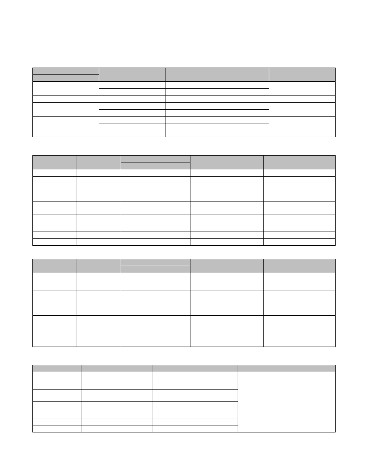
Instruction Manual
D103466X012
Table 17. Key 23* Graphite Piston Rings for Valves With Balanced Trim
PORT DIAMETER
Inch
2.875
3.625 Yes 14B5340X022 1 or 2
5.375
7
10 Yes GG62197X022
Table 18. Key 7 Body/Bonnet Mounting Studs
VALVE SIZE, NPS QUANTITY
1/2 8 1 1/8-8 x 7.00 12A3576 SA 453 660 A
1
2
3 8 1 3/8-8 x 6.75 15A5490
4 8 1 1/4-8 x 6.00 10A1461
5
6
8 x 6
8 12 1 7/8-8 x 9.25 GE46825 SA 453 660 A
10 x 14 12 2 1/2-8 x 14.00 GE02851 SA 453 660 A
USE WITH C-SEAL? PISTON RING PART NUMBER QUANTITY
Yes 14B3620X032
No 1U2300X0042
Yes 13B9186X022
No 11A9727X052
Yes 13B9176X022
No 1U5069X0052
STUD SIZE
Inch
8 1 1/8-8 x 5.75 1J9582
8
1 1/2-8 x 8.00 12A5151 SA 453 660 A
1 1/2-8 x 7.25 14B3926 SA 193 B7
PART NUMBER MATERIAL
HPNS Valve
March 2022
2
3
2
SA 453 660 A
SA 193 B7
SA 453 660 A
SA 193 B7
SA 453 660 A
SA 193 B7
Table 19. Key 8 Body/Bonnet Mounting Nuts
VALVE SIZE, NPS QUANTITY
1/2
1
2
3 8 1 3/8-8 1D7167
4 8 1 1/4-8 1A4453
5
6
8 x 6
8 12 1 7/8-8 1A5013 SA 453 660 A
10 x 14 12 2 1/2-8 1P3683 SA 453 660 A
8 1 1/8-8 1A4452
8 1 1/2-8 1A5011
STUD SIZE
Inch
PART NUMBER MATERIAL
Table 20. Key 24 Body/Bonnet Mounting Washers
VALVE SIZE, NPS QUANTITY PART NUMBER MATERIAL
1/2
1
2
3
4
5
6
8x6
8 12 18A8861
10x14 12 19A1043
8 F16342
8 10A2630
S41600
8 18A8227
SA 453 660 A
SA 194 2H
SA 453 660 A
SA 194 2H
SA 453 660 A
SA 194 2H
SA 453 660 A
SA 194 2H
*Recommended spare parts
47
Page 48

HPNS Valve
March 2022
Instruction Manual
D103466X012
Table 21. Key 4* Valve Plug/Stem Assemblies
VALVE
SIZE, NPS
1/2 Unbalanced Yes 0.25 19.1 0.75 0.25 GG34905X012 Alloy 6B/S20910
1 Unbalanced
2 Unbalanced
3
4
5
6
8 x 6 Balanced No 4.375 25.4 1 3 GG52297X012 F6NM/S41000
8
10 x 14 Balanced No 10 31.8 1.25 4 GH07603X012 F6NM/S41000
DESCRIPTION BACKSEAT
Yes 0.25 12.7 0.5 0.75 GE45478X012
Yes 0.75 12.7 0.5 0.75 GE45433X012
No 0.75 12.7 0.5 1.25 GE45483X012
Yes 0.75 19.1 0.75 0.75 GG66432X012
No 1 12.7 0.5 0.75 GE45480X012
No 1 19.1 0.75 0.75 GG66462X012
Yes 1 19.1 0.75 2 GE61266X012 Alloy 6B/S20910
No 1.875 19.1 0.75 1.5 GE47992X012
Yes 1.875 25.4 1 1.125 GE48011X012
Yes 1.875 25.4 1 1.5 GE48003X012
No 1.875 25.4 1 1.5 GE50402X012
Unbalanced Yes 2.875 19.1 0.75 2 GE44619X012
Balanced,
Bore Seal
Balanced No 2.875 12.7 0.5 1.5 GE44700X12
Balanced,
Bore Seal
Balanced,
Bore Seal
Balanced No 5.375 25.4 1 1.75 GG50029X022 F22/COCR-A/S20910
Balanced No 5.375 25.4 1 3 GG50029X012 S31603/COCR-A/S20910
Balanced No 5.375 19.1 0.75 3 GE44582X012 S31603/COCR-A/S20910
Balanced,
Bore Seal
Balanced,
Bore Seal
Balanced No 7 25.4 1 2 GG50217X012 S31603/COCR-A/S20910
Yes 2.875 25.4 1 2 GE44639X012
No 3.625 19.1 0.75 2 GE44436X012 S31603/COCR-A/S20910
Yes 3.625 25.4 1 2 GE44516X012 F22/S31600/S20910
No 3.625 25.4 1 2 GE44534X012 F22/COCR-A/S20910
Yes 5.375 25.4 1 1.75 GG49817X012 F22/COCR-A/S31600/S20910
No 5.25 25.4 1 3 GE49248X012 F6NM/S41000
No 7 25.4 1 2.25 GE45907X012 S31603/COCR-A/S20910
PORT
DIAMETER
Inch mm Inch Inch
STEM DIAMETER TRAVEL
PART NUMBER MATERIAL
Alloy 6B/S20910
S31603/COCR-A/S20910
S31603/COCR-A/S20910
Table 22. Key 25* Retainers for Valves With Bore Seal
VALVE SIZE,
NPS
3 2.875 V 2 25.4 1 GE35717X022 S31603/COCR-A
4 3.625 V
5
6
8 7 V 2 25.4 1 GE19242X032 S31603/COCR-A
48
PORT
DIAMETER
Inch mm Inch
5.375 V 2 25.4 1 GE57237X022 F22/COCR-A
SHUTOFF
CLASS
PISTON
RINGS
NEEDED
1
2
STEM DIAMETER
25.4 1
*Recommended spare parts
PART NUMBER MATERIAL
GE48307X012 F22/COCR-A
GE14715X022 F22/COCR-A
GE14715X032 S31603/COCR-A
Page 49

Instruction Manual
D103466X012
Table 23. Key 26* Bore Seal Part Numbers for Valves With Bore Seal Trim
VALVE SIZE, NPS
3 2.875 GE14956X012
4 3.625 GE14658X012
5
6
8 7 23B9182X012
10 x 14 10 GG62213X012
Table 24. Yoke Bolt Circle Diameter
ACTUATOR SIZE YOKE BOSS DIAMETER (INCH)
45A 11.35
45B 13.48
70A 11.35
70B 13.48
70C 15.3
80A 11.35
80B 13.48
80C 15.3
PORT DIAMETER
Inch
5.375 24B2191X012
HPNS Valve
March 2022
BORE SEAL PART NUMBER
Table 25. Keys 29*, 30*, 31*, 32*, and 33* Part Numbers for Valves Using Bidirectional PEEK Anti-Extrusion Seal
Rings
PART DESCRIPTION KEY NUMBER QUANTITY
Backup Ring 29* 1 10A4224X282 17A4397X012
Anti-Extrusion Ring 30* 2 21B9341X012 21B2142X012
Spring Loaded Seal Ring 31* 2 GE44061X012 GE43856X012
Spacer Ring 32* 1 GG52367X012 GG09153X012
Retainer Ring 33* 1 10A4225X012 17A4398X012
4.375-inch Port Diameter 5.25-inch Port Diameter
PART NUMBER
Table 26. Key 35* Part Numbers for Bellows/Stem Assembly
VALVE SIZE, NPS PART DESCRIPTION KEY NUMBER QUANTITY
1/2 Bellows/Stem Assembly 35* 1 0.25 GG35420X012
PORT DIAMETER,
INCH
PART NUMBER
Table 27. Key 36* Cage Gasket
VALVE SIZE, NPS QUANTITY
10 x 14 4 GG62169X022
GASKET PART NUMBER
Cage Gasket (Key 36*)
Table 28. Key 37* Cage Retainer
VALVE SIZE, NPS PART NUMBER MATERIAL
10 x 14 GH08913 S31603
*Recommended spare parts
49
Page 50

HPNS Valve
March 2022
Instruction Manual
D103466X012
50
Page 51

Instruction Manual
D103466X012
HPNS Valve
March 2022
51
Page 52

HPNS Valve
March 2022
Instruction Manual
D103466X012
Neither Emerson, Emerson Automation Solutions, nor any of their affiliated entities assumes responsibility for the selection, use or maintenance
of any product. Responsibility for proper selection, use, and maintenance of any product remains solely with the purchaser and end user.
Fisher, Cavitrol, and Whisper Trim are marks owned by one of the companies in the Emerson Automation Solutions business unit of Emerson Electric Co.
Emerson Automation Solutions, Emerson, and the Emerson logo are trademarks and service marks of Emerson Electric Co. All other marks are the property
of their respective owners.
The contents of this publication are presented for informational purposes only, and while every effort has been made to ensure their accuracy, they are not
to be construed as warranties or guarantees, express or implied, regarding the products or services described herein or their use or applicability. All sales are
governed by our terms and conditions, which are available upon request. We reserve the right to modify or improve the designs or specifications of such
products at any time without notice.
Emerson Automation Solutions
Marshalltown, Iowa 50158 USA
Sorocaba, 18087 Brazil
Cernay, 68700 France
Dubai, United Arab Emirates
Singapore 128461 Singapore
www.Fisher.com
52
E 2010, 2022 Fisher Controls International LLC. All rights reserved.
 Loading...