

Page 1

Instruction Manual
D100391X012
Fisher™ EDR and ETR easy-e™ Valves
EDR and ETR Valves
July 2017
Contents
Introduction 1.................................
Scope of Manual 1.............................
Description 1.................................
Specifications 2...............................
Educational Services 2.........................
Installation 4..................................
Maintenance 5.................................
Trim Maintenance 5...........................
Packing Maintenance 9.........................
Parts Ordering 15...............................
Packing Kits 16.................................
Parts Kits 19...................................
Parts List 20...................................
Introduction
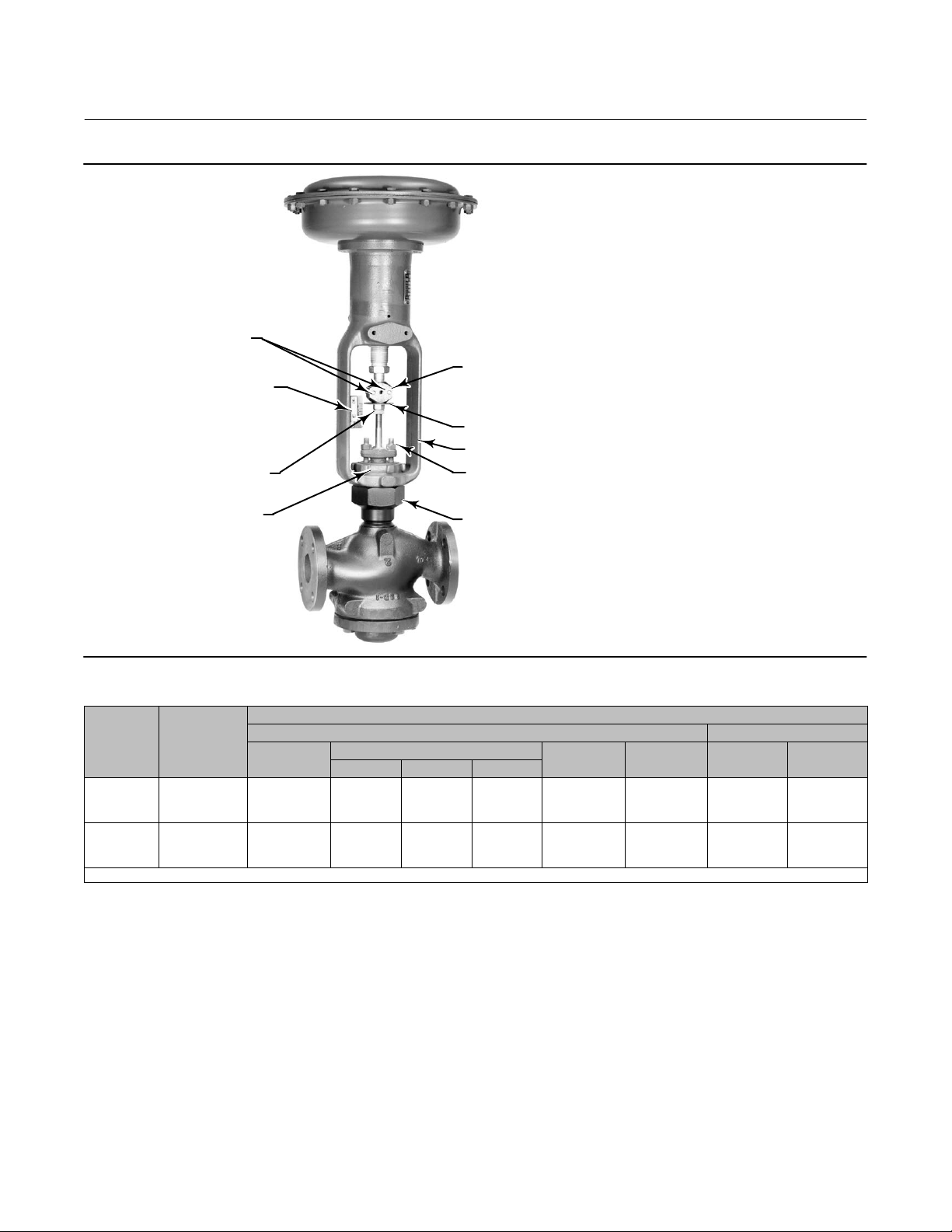
Figure 1. Reverse Acting easy‐e Valve with Actuator
W2080‐1
Scope of Manual
This instruction manual includes installation, maintenance, and parts information for NPS 1 through 4 EDR and ETR
valves (see figure 1). The valves are available in CL150 through 600 ratings.
The valves are also available with full‐size and restricted‐trim designs. Refer to separate manuals for instructions
covering the actuator and accessories.
Do not install, operate, or maintain an EDR or ETR valve without being fully trained and qualified in valve, actuator, and
accessory installation, operation, and maintenance. To avoid personal injury or property damage, it is important to
carefully read, understand, and follow all the contents of this manual, including all safety cautions and warnings. If you
have any questions about these instructions, contact your Emerson sales office
proceeding.
or Local Business Partner before
Description
The EDR and ETR are single‐port, globe‐style valves that feature cage guiding, a balanced plug design, and
push‐down‐to‐open valve plug action. The valve constructions are available with metal‐to‐metal or
metal‐to‐composition seats. These constructions permit access to the internal trim parts through the bottom flange
without removing the actuator from the valve.
www.Fisher.com
Page 2

EDR and ETR Valves
July 2017
Table 1. Specifications
Instruction Manual
D100391X012
Available Valve Constructions
See table 2
Shutoff Classification
EDR: ANSI/FCI 70‐2 and IEC 60534‐4 Class II
(standard); Class III for valves with a graphite piston
ring and 78 mm (3.4375 inch) or larger port diameter
End Connection Styles
Cast Iron Valves
Flanged: CL125 flat‐face or 250 raised‐face flanges per
ASME B16.1
Steel and Stainless Steel Valves
Flanged: CL150, 300, and 600 raised‐face or ring‐type
joint flanges per ASME B16.5
Screwed or Socket Welding: All available ASME B16.11
ETR: Standard air test
(0.05 mL/minute/psid/inch of port diameter) using air
at service pressure drop or 3.5 bar (50 psi), whichever
is lower; or ANSI/FCI 70‐2 and
IEC 60534‐4 Class V (optional) with PTFE seats; Class
IV or V (optional) with metal seats
Flow Characteristics
Linear (all cages), quick‐opening, or equal percentage
schedules that are consistent with CL600 per ASME
B16.34
Buttwelding: Consistent with ASME B16.25
Flow Directions
Linear, Quick Opening, or Equal Percentage Cage:
Normally up,
™
Maximum Inlet Pressure
(1)
Whisper Trim
Approximate Weights
Cast Iron Valves
Flanged: Consistent with CL125B or 250B
pressure‐temperature ratings per ASME B16.1
Steel and Stainless Steel Valves
Flanged: Consistent with CL150, 300, and 600
(2)
pressure‐temperature ratings per ASME B16.34
Screwed or Welding: Consistent with CL600
pressure‐temperature ratings per ASME B16.34
1. The pressure/temperature limits in this manual and any applicable standard or code limitation for the valve should not be exceeded.
2. Certain bonnet bolting material selections may require a CL600 easy‐e valve assembly to be derated. Contact your Emerson sales office
VALVE SIZE,
NPS
1 & 1‐1/4
1‐1/2
2
2‐1/2
3
4
I Cage: Always down
kg Pounds
14
20
39
45
54
77
or Local Business Partner.
WEIGHT
30
45
67
100
125
170
Educational Services
For information on available courses for Fisher EDR and ETR valves, as well as a variety of other products, contact:
Emerson Automation Solutions
Educational Services - Registration
Phone: 1-641-754-3771 or 1-800-338-8158
E-mail: education@emerson.com
emerson.com/fishervalvetraining
2
Page 3
Instruction Manual
D100391X012
Figure 2. Actuator Mounting
CAP SCREWS
INDICATOR SCALE
STEM LOCKNUTS
EDR and ETR Valves
July 2017
STEM CONNECTOR
INDICATOR DISK
ACTUATOR YOKE
PACKING FLANGE NUTS
YOKE LOCKNUT
W2080‐1
Table 2. Available Valve Constructions
VALVE
DESIGN
EDR
ETR
X = Available Construction
VALVE
SIZE,
NPS
1, 1‐1/2, or 2
1‐1/4
2‐1/2, 3, or 4
1, 1‐1/2, or 2
1‐1/4
2‐1/2, 3, or 4
Screwed
X
X
‐ ‐ ‐
X
X
‐ ‐ ‐
BONNET
VALVE MATERIAL AND END CONNECTION STYLE
Carbon Steel, Alloy Steel, or Stainless Steel Valve Cast Iron Valve
RF or RTJ Flanged
CL150 CL300 CL600
X
‐ ‐ ‐
X
X
‐ ‐ ‐
‐ ‐ ‐
‐ ‐ ‐
‐ ‐ ‐
‐ ‐ ‐
X
X
X
X
‐ ‐ ‐
X
X
‐ ‐ ‐
‐ ‐ ‐
Butt‐
welding
X
‐ ‐ ‐
X
X
‐ ‐ ‐
‐ ‐ ‐
Socket
Weld
X
‐ ‐ ‐
‐ ‐ ‐
X
‐ ‐ ‐
‐ ‐ ‐
CL125B
FF Flanged
X
‐ ‐ ‐
X
‐ ‐ ‐
‐ ‐ ‐
‐ ‐ ‐
CL250B
RF Flanged
X
‐ ‐ ‐
X
‐ ‐ ‐
‐ ‐ ‐
‐ ‐ ‐
3
Page 4

EDR and ETR Valves
July 2017
Instruction Manual
D100391X012
Installation
WARNING
Always wear protective gloves, clothing, and eyewear when performing any installation operations.
To avoid personal injury or property damage resulting from the sudden release of pressure, do not install the valve
assembly where service conditions could exceed the limits given on the valve and actuator nameplates. Use
pressure‐relieving devices as required by accepted industry, local, state, or Federal codes, and good engineering practices.
Check with your process or safety engineer for any other hazards that may be present from exposure to process media.
If installing into an existing application, also refer to the WARNING at the beginning of the Maintenance section in this
instruction manual.
CAUTION
The valve configuration and construction materials were selected to meet particular pressure, temperature, pressure drop,
and controlled fluid conditions. Because some body/trim material combinations are limited in their pressure drop and
temperature range capabilities, do not exceed these conditions without first contacting your Emerson sales office
Business Partner.
Inspect the valve and pipelines to ensure they are not damaged, are clean, and free of foreign material.
or Local
1. Before installing the valve, inspect the valve and associated equipment for any damage and any foreign material.
2. Make certain the valve body interior is clean, that pipelines are free of foreign material, and that the valve is
oriented so that pipeline flow is in the same direction as the arrow (see figure 2) on the side of the valve.
3. The control valve assembly can be installed in any orientation unless limited by seismic criteria. However, the
normal method is with the actuator vertical above the valve body (see figure 2). Other positions may result in
uneven valve plug and cage wear, and improper operation. With some valves, the actuator may also need to be
supported when it is not vertical. For more information, consult your Emerson sales office or Local Business Partner.
4. Use accepted piping and welding practices when installing the valve in the line. If a post‐weld heat treatment
process is to be applied to the valve end connections, and the valve has composition or elastomer trim parts,
remove the trim to avoid damage to the soft parts.
CAUTION
Depending on valve body materials used, post weld heat treating may be required. If so, damage to internal elastomeric
and plastic parts, as well as internal metal parts is possible. Shrunk‐fit pieces and threaded connections may loosen. In
general, if post weld heat treating is to be performed, all trim parts should be removed. Contact your Emerson sales office
or Local Business Partner for additional information.
5. If continuous operation is required during inspection or maintenance, install a three‐valve bypass around the
control valve assembly.
6. If the actuator and valve are shipped separately, refer to the actuator mounting procedure in the appropriate
actuator instruction manual and also see figure 2.
WARNING
Personal injury could result from packing leakage. Valve packing was tightened prior to shipment; however some
readjustment will be required to meet specific service conditions.
4
Page 5

Instruction Manual
D100391X012
EDR and ETR Valves
July 2017
Maintenance
WARNING
Avoid personal injury from sudden release of process pressure. Before performing any maintenance operations:
D Do not remove the actuator from the valve while the valve is still pressurized.
D Always wear protective gloves, clothing, and eyewear when performing any maintenance operations to avoid personal
injury.
D Disconnect any operating lines providing air pressure, electric power, or a control signal to the actuator. Be sure the
actuator cannot suddenly open or close the valve.
D Use bypass valves or completely shut off the process to isolate the valve from process pressure. Relieve process pressure
on both sides of the valve. Drain the process media from both sides of the valve.
D Vent the power actuator loading pressure and relieve any actuator spring precompression.
D Use lock‐out procedures to be sure that the above measures stay in effect while you work on the equipment.
D The valve packing box may contain process fluids that are pressurized, even when the valve has been removed from the
pipeline. Process fluids may spray out under pressure when removing the packing hardware or packing rings, or when
loosening the packing box pipe plug.
D Check with your process or safety engineer for any additional measures that must be taken to protect against process
media.
Valve parts are subject to normal wear and must be inspected and replaced as necessary. Inspection and maintenance
frequency depends on the severity of service conditions. This section includes instructions for trim maintenance,
packing maintenance, and packing lubrication. All maintenance operations may be performed with the valve installed
in the pipeline.
Note
If the valve has ENVIRO‐SEAL
ENVIRO‐SEAL Packing System for Sliding‐Stem Valves (D101642X012
™
live‐loaded packing installed (figure 8, 9, or 10), see the Fisher instruction manual entitled
) for packing instructions.
Trim Maintenance
Disassembly
Note
Whenever a gasket seal is disturbed by removing or shifting gasketed parts, install a new gasket upon reassembly. This is necessary
to ensure a good gasket seal.
Key number locations are shown in figure 11 or 12 unless otherwise indicated.
5
Page 6

EDR and ETR Valves
July 2017
Figure 3. Valve Plug Assembly
Instruction Manual
D100391X012
STEM
DISK SEAT
DISK
VALVE PLUG
CAGE
1
40A5479‐B
B2360
NOTE:
1
ETR OR EDR
ETR USES A SEAL RING (KEY 24) AND A BACKUP RING (KEY 25) (SEE FIGURE 11).
CASTLE NUT
COTTER PIN
CAUTION
Take care when removing the bottom flange (key 31) in the following procedure, to prevent possible product damage from
parts unexpectedly falling out of the valve body.
1. Isolate the control valve from the line pressure, release pressure from both sides of the valve body, and drain the
process media from both sides of the valve. If using a power actuator, also shut off all pressure lines to the power
actuator, release all pressure from the actuator. Use lock‐out procedures to be sure that the above measures stay in
effect while you work on the equipment. When removing the bottom flange (key 31), be careful that the cage and
other parts are not damaged by unexpectedly falling out of the valve body. Remove the nuts (key 16) or cap screws
from the bottom flange.
2. Removing the valve plug from the valve body, the valve plug can be removed independently of the valve stem by
removing the cotter pin and castle nut (keys 30 and 8). Then, slide the valve plug out of the cage (see figure 3).
D Disconnect the stem connector, and loosen the packing flange nuts (see figure 2).
D Move the valve stem away from the actuator stem allowing room to remove the indicator disk and stem locknuts.
Remove the parts indicated.
D Remove the valve plug by pulling the valve plug/stem assembly through the packing and out of the bottom of the
bonnet.
D If the valve plug is to be re‐used but the stem needs to be replaced, drive the pin (key 8) out of the plug/stem
assembly and unscrew the valve stem.
CAUTION
Take care during disassembly in the following procedure, to prevent possible damage to sealing surfaces.
6
Page 7

Instruction Manual
D100391X012
EDR and ETR Valves
July 2017
3. Remove the seat ring (key 9), gaskets (keys 10, 11, 12, and 13), and any remaining parts if they did not come out
with the valve plug. If the seat ring (key 9) is stuck in the valve body, strike the outside of the valve body at the seat
ring line with a rubber hammer while pulling down on the seat ring. Carefully remove the seat ring without
damaging sealing surfaces.
If necessary, machine or grind metal seats before installing the piston ring/seal ring or packing, or refer to the Lapping
Metal Seats procedure in this section.
CAUTION
The pressure balancing holes in the valve plug are necessary for the proper and safe operation of the valve. Inspect the
balancing holes every time the valve is disassembled for service. Any build-up, blockage, or clogging of the balance holes
should be removed.
Lapping Metal Seats
A certain amount of leakage should be expected with metal‐to‐metal seating in any valve body. If the leakage
becomes excessive, however, the condition of the seating surfaces of the valve plug and seat ring can be improved by
lapping. (Deep nicks should be machined out rather than ground out.) Use a good quality lapping compound of a
mixture of 280 to 600‐grit.
Assemble the valve to the extent that the seat ring (key 9), cage (key 3), cage adaptor (key 4, if used), and bonnet are
in place. Also, remove the piston ring or seal ring from the valve plug (if used).
1. Insert the valve stem (key 7) into the bonnet and thread the plug (key 2) onto the end of the stem. Make a simple
handle from a piece of strap iron; lock it to the valve with the stem locknuts.
2. Apply the lapping compound to the seating surfaces. Rotate the handle alternately in each direction to lap the
seats. After lapping the seats, remove the valve plug and stem, then clean all parts. Repeat the lapping procedure if
necessary.
Trim Assembly
Carefully clean all gasket surfaces. Use new gaskets during reassembly of the valve.
Table 3. Valve Body‐to‐Flange Nut Torques
VALVE
SIZE,
NPS
1 and 1‐1/4 129 95 64 47
1‐1/2, 1‐1/2 x 1, 2, or 2 x 1 96 71 45 33
2‐1/2, 2‐1/2 x 1‐1/2, or 3 x 1‐1/2 129 95 64 47
3, 3 x 2, 3 x 2‐1/2, or 4 x 2 169 125 88 65
4, 4 x 2‐1/2, or 4 x 3 271 200 156 115
1. Determined from laboratory tests.
2. SA193‐B8M annealed.
3. For other materials, contact your Emerson sales office
or Local Business Partner.
(3)
TORQUES
SA193‐B7 SA193‐B8M
NSm LbfSft NSm LbfSft
(1)
(2)
Replacing the Seal or Piston Ring
CAUTION
Be careful not to scratch the surface of the ring groove in the valve plug (key 2), or the new ring may not seal properly.
7
Page 8

EDR and ETR Valves
July 2017
Instruction Manual
D100391X012
D For EDR, if the piston ring (key 6) is visibly damaged, remove the ring and replace it with a new part. Refer to the
Parts List at the end of this manual for a replacement part.
D For ETR, if the seal ring and backup ring (keys 24 and 25) are visibly damaged, remove the rings by prying or cutting
them from the groove. Be careful not to scratch valve plug surfaces. Refer to the Parts List at the end of this manual
for replacement parts.
Assembling the Valve Plug and Stem
1. For EDR and ETR, perform the following steps:
D Insert the stem (key 7) into the plug (key 2, figure 3) and thread the castle nut (key 8) onto the end of the stem and
hand tighten.
CAUTION
To prevent possible product damage, take care that the stem and plug are not damaged during the following tightening
procedure.
D When tightening the castle nut with a wrench, line up the hole in the end of the stem with a slot in the castle nut.
Ensure that the stem and plug are not damaged during the tightening procedure.
D Insert the cotter pin (key 30) and lock it in place.
Installing the Piston Rings or Backup Ring/Seal Rings
1. For EDR: When using a carbon‐filled PTFE piston ring, spread the ring apart slightly at the split, start one end of the
split into the groove in the valve plug. Work the ring around the valve plug inserting the ring into the groove in the
valve plug.
The replacement graphite piston rings will arrive in one piece. Use a vise with smooth or tapered jaws to break the
replacement piston ring into two halves. Place the new ring in the vise so that the jaws compress the ring into an oval.
Compress the ring slowly until the ring snaps on both sides. If one side snaps first, do not try to tear or cut the other
side. Instead, keep compressing the ring until the other side snaps. The piston ring can also be fractured by scoring and
snapping over a hard surface such as a table edge. Sawing or cutting the ring is not recommended.
2. For ETR: Apply a lubricant to both backup and seal rings (keys 25 and 24). Place the backup ring over the stem (key
7) and into the groove in the valve plug (key 3). Slowly and gently stretch the seal ring over the valve plug and work
it into the groove. Stretching the ring over the valve plug can cause it to appear too large for the groove, but it will
contract to its original size when inserted into the cage.
CAUTION
When installing the EDR or ETR valve plug into the cage, make sure the piston or seal ring is evenly engaged in the entrance
chamfer of the cage to avoid damage to the ring.
Note
Use the preceding procedures to assemble the valve plug and stem before installing the parts into the valve body. Insert the valve
plug into the cage (figure 3), then stack the parts as recommended in steps below.
8
Page 9

Instruction Manual
D100391X012
EDR and ETR Valves
July 2017
Installing the Parts into the Valve Body
1. Stack the valve trim parts using figures 11 and 12 to determine the sequence of parts.
2. Lubricate the stud bolts (key 15) before installing the valve trim into the valve body. (Note: For ease of installing
trim parts, remove all packing parts from the packing box before installing the trim parts.)
3. When inserting the stack of trim parts into the valve body, carefully align the parts in the recess of the valve body.
4. Slide the bottom flange onto the stud bolts (key 15). Secure the bottom flange (key 31) in place on the valve body
with the hex nuts (key 16). Tighten the hex nuts to the torque value shown in table 3.
5. Torque the nuts in a criss‐cross pattern. Repeat the pattern until all nuts are torqued to the value indicated in table
3.
6. Refer to the Packing Maintenance procedures below.
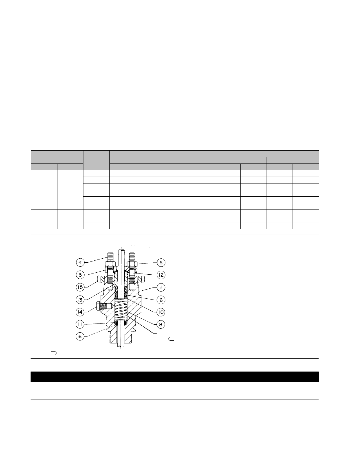
Packing Maintenance
This procedure covers PTFE V‐ring, graphite ribbon/filament, and PTFE composition packing rings. Key numbers refer
to figure 5 for PTFE V‐ring packing and PTFE/composition packing, unless otherwise indicated.
Note
If the valve has ENVIRO‐SEAL live‐loaded packing installed (figure 8, 9, or 10), see the Fisher instruction manual entitled
ENVIRO‐SEAL Packing System for Sliding‐Stem Valves (D101642X012
For all except spring‐loaded packing, if the packing is relatively new and tight on the stem, and if tightening the
packing flange nuts does not stop the leakage, it is possible that the valve stem is worn or nicked so that a seal cannot
be made. If the leakage comes from the outside diameter of the packing follower, it is possible that the leakage is
caused by nicks or scratches around the inside of the packing box wall.
For spring‐loaded single PTFE V‐ring packing, the spring (key 8) maintains a sealing force on the packing. If leakage is
noted around the packing follower (key 13), check to be sure the shoulder on the packing follower is touching the
bonnet. If the shoulder is not touching the bonnet, tighten the packing flange nuts (key 5, figure 4) until the shoulder
is against the bonnet. If leakage cannot be stopped in this manner, proceed to the Removing Packing and Installing
Packing procedures below.
) for packing instructions.
Removing Packing
WARNING
Refer to the WARNING at the beginning of the Maintenance section in this instruction manual.
The packing may have been removed in earlier steps, or during trim maintenance procedures. Use the following steps,
when necessary, to remove packing and associated assemblies.
Key number locations for packing parts are shown in figures 5 and 6. For valve parts and the live loaded packing
system, refer to figures 8 through 10 (in the Parts List section), for key number locations.
1. Isolate the control valve from the line pressure, release pressure from both sides of the valve body, and drain the
process media from both sides of the valve. If using a power actuator, also shut off all pressure lines to the power
9
Page 10
EDR and ETR Valves
July 2017
Instruction Manual
D100391X012
actuator and release all pressure from the actuator. Use lock‐out procedures to be sure that the above measures
stay in effect while you work on the equipment.
2. Exhaust all actuator pressure, disconnect the operating lines from the actuator, and disconnect any leakoff piping
from the actuator. Relieve any actuator precompression from the stem connector. (If necessary, refer to the
appropriate actuator instruction manual for warnings, cautions, and disassembly procedures.)
3. When removing the bottom flange (key 31), be careful that the cage and other parts are not damaged by
unexpectedly falling out of the valve body. Remove the nuts (key 16) or cap screws from the bottom flange.
4. To remove the packing for maintenance, disconnect the stem connector (see figure 2). Remove the yoke locknut,
and lift the actuator off the valve.
5. Remove the packing flange nuts (key 5, figure 4), packing flange (key 15), upper wiper (key 12), and packing
follower (key 13). If maintaining the packing while the valve stem is in place, ensure that the valve stem surface is
not scratched or marred while working with the packing.
Table 4. Recommended Torque for Packing Flange Nuts
VALVE STEM
DIAMETER
mm Inches NSm LbfSin NSm LbfSin NSm LbfSin NSm LbfSin
9.5 3/8
12.7 1/2
19.1 3/4
PRESSURE
RATING
CL125, 150 3 24 5 48 1 12 3 24
CL250, 300 4 36 7 60 2 18 3 30
CL600 5 48 8 72 3 24 4 36
CL125, 150 5 48 8 72 3 24 4 36
CL250, 300 7 60 10 84 3 30 5 42
CL600 10 84 14 120 5 42 7 60
CL125, 150 11 96 16 144 5 48 8 72
CL250, 300 14 120 20 180 7 60 10 90
CL600 20 180 30 264 10 90 15 132
Minimum Torque Maximum Torque Minimum Torque Maximum Torque
GRAPHITE PACKING PTFE PACKING
Figure 4. Bonnet Assembly
PACKING
1
10A6681‐A
NOTE:
1
REFER TO FIGURE 5 OR 6 FOR PACKING ARRANGEMENTS.
BOX
CAUTION
To prevent possible product damage, avoid scratching the packing box walls when removing old packing parts. Also
inspect valve stem threads and packing box surfaces for sharp edges which may damage packing.
10
Page 11

Instruction Manual
D100391X012
EDR and ETR Valves
July 2017
6. Avoid scratching the packing box walls when removing the old packing parts. Clean the packing box (see figure 4),
and clean, inspect, or replace metal packing parts. Generally, the metal packing parts are not part of the packing
kits listed in the Parts List section, and they must be ordered individually.
7. Inspect the valve stem threads and packing box surfaces for any sharp edges which might cut the packing.
Scratches or burrs on the stem surfaces can cause packing box leakage or damage to new packing. If the surface
condition cannot be improved by light sanding, replace the damaged parts by following the appropriate steps in the
Trim Maintenance procedure.
Note
If the control valve assembly was purchased for an application where the service temperatures are under 232_C (450_F), the
bonnet may be unscrewed from the valve body. Where temperatures are greater than 232_C (450_F), the bonnet is seal welded to
the valve body.
CAUTION
To prevent possible product damage, set the bonnet on a protective surface in the following procedure.
8. If necessary, remove the bonnet assembly from the valve by unscrewing it. Some applications require seal welding
the bonnet to the valve body, and the bonnet should not be removed. Set the bonnet on a protective surface to
prevent damage to the bonnet gasket surface.
11
Page 12

EDR and ETR Valves
July 2017
Figure 5. Packing Arrangements
UPPER WIPER
(KEY 12)
PACKING
FOLLOWER
(KEY 13)
WASHER
(KEY 10)
SPRING
(KEY 8)
PACKING BOX
RING (KEY 11)
FOR S31600 (316 SST) OR S17400 (17‐4PH)
NOTES:
1
SECTION FOR THE SPACER AND OTHER METAL PARTS.
2
12A7837‐A
B2358‐1
REFER TO THE VALVE SERIAL NUMBER AND THE PARTS ORDERING
PACKING SET (KEY 6) (2 REQ'D FOR DOUBLE ARRANGEMENTS).
SST METAL PACKING BOX PARTS
FEMALE
ADAPTOR
PACKING RING
MALE
ADAPTOR
2
LOWER WIPER
2
2
2
FEMALE
2
ADAPTOR
PACKING RING
2
MALE
2
ADAPTOR
LOWER WIPER
2
TYPICAL SINGLE ARRANGEMENTS
Instruction Manual
UPPER WIPER
(KEY 12)
PACKING
FOLLOWER
(KEY 13)
SPACER (KEY 8)
PACKING BOX
RING (KEY 11)
FOR ALL OTHER METAL PACKING
BOX PART MATERIALS
D100391X012
1
12A8187-C
ASSEMBLY 1
(POSITIVE
PRESSURES)
ASSEMBLY 2
(VACUUM)
ASSEMBLY 3
(POSITIVE
PRESSURES
& VACUUM)
12A7814-C
ASSEMBLY 1
(POSITIVE
PRESSURES)
ASSEMBLY 2
(VACUUM)
ASSEMBLY 3
(POSITIVE
PRESSURES
& VACUUM)
12A7839-A
ASSEMBLY 1
(POSITIVE
PRESSURES)
ASSEMBLY 2
(VACUUM)
9.5mm (3/8 INCH) STEM 12.7 mm (1/2 INCH) STEM 19.1 mm (3/4 INCH) STEM
B2359
TYPICAL DOUBLE ARRANGEMENTS
ASSEMBLY 3
(POSITIVE
PRESSURES
& VACUUM)
UPPER WIPER
(KEY 12)
PACKING
FOLLOWER
(KEY 13)
MALE
ADAPTOR
PACKING RING
FEMALE
ADAPTOR
LANTERN RING
(KEY 8)
PACKING BOX
RING (KEY 11)
LOWER WIPER
12
Page 13

Instruction Manual
D100391X012
Figure 6. Packing Arrangements
EDR and ETR Valves
July 2017
UPPER WIPER (KEY 12)
PACKING FOLLOWER (KEY 13)
PACKING RING (KEY 7)
LANTERN RING (KEY 8)
PACKING BOX RING (KEY 11)
NOTE:
1
0.102 mm (0.004 INCH) THICK SACRIFICIAL
ZINC WASHERS; USE ONLY ONE BELOW
EACH GRAPHITE RIBBON RING.
A5864
12A8188‐A
12A7815‐A
12A8173‐A
A2619‐3
9.5 mm
(3/8 INCH)
STEM
12.7 mm
(1/2 INCH)
STEM
19.1 mm
(3/4 INCH)
STEM
TYPICAL (DOUBLE) ARRANGEMENTS
DETAIL OF PTFE/COMPOSITION PACKING
STEM
1
13A9776-B
19.1 mm
(3/4 INCH)
STEM
1
14A3411-A
9.5 mm
(3/8 INCH)
STEM
1
13A9775-B
12.7 mm
(1/2 INCH)
SINGLE ARRANGEMENTS
STEM
1
1
14A1780-B
19.1 mm
(3/4 INCH)
STEM
1
14A2153-B
9.5 mm
(3/8 INCH)
STEM
1
14A1849-B
12.7 mm
(1/2 INCH)
DOUBLE ARRANGEMENTS
DETAIL OF GRAPHITE RIBBON/ FILAMENT PACKING
PACKING FOLLOWER (KEY 13)
GRAPHITE RIBBON PACKING RING (KEY 7)
GRAPHITE FILAMENT PACKING RING (KEY 7)
LANTERN RING (KEY 8)
PACKING BOX RING (KEY 11)
PACKING FOLLOWER (KEY 13)
GRAPHITE RIBBON PACKING RING (KEY 7)
GRAPHITE FILAMENT PACKING RING (KEY 7)
LANTERN RING (KEY 8)
PACKING BOX RING (KEY 11)
13
Page 14

EDR and ETR Valves
July 2017
Instruction Manual
D100391X012
Installing Packing
If the trim is removed, refer to Trim Maintenance procedures, and install the trim (including the valve stem) before
installing the packing. If necessary, use the Lapping Metal Seats procedures before installing packing. Key number
locations are shown in figure 5 or 6 unless otherwise indicated.
CAUTION
To prevent possible product damage, take care when installing the bonnet over the valve stem in the following procedure.
1. If the bonnet has been removed from the valve body, install the replacement bonnet (see figure 4). Carefully slide
the bonnet over the valve stem without damaging the stem surfaces.
2. Refer to figure 5 or 6 for the sequence of parts to make up the appropriate packing set for your application. Arrange
the packing parts in sequence before installing them into the packing box.
3. For split‐ring packing, alternate the positions of the splits to avoid creating a leak path. Place a smooth‐edged pipe
over the valve stem and gently tap each soft packing ring into the packing box. Be sure that air is not trapped
between adjacent soft parts.
4. Install the packing follower (key 13), packing flange (key 3), and upper wiper (key 12, if required). Install the packing
flange nuts (key 5).
5. Refer to actuator installation procedures in the actuator instruction manual, and the installation procedures in the
manual when mounting and connecting the actuator to the valve. If lubrication is required, refer to the Packing
Lubrication section below.
6. For spring‐loaded PTFE V‐ring packing, tighten the packing flange nuts until the shoulder on the packing follower
(key 13, figure 4) contacts the bonnet.
For graphite packing, tighten the packing flange nuts to the maximum recommended torque shown in table 4. Then,
loosen the packing flange nuts, and retighten them to the recommended minimum torque shown in table 4.
For other packing types, tighten the packing flange nuts alternately in small equal increments until one of the nuts
reaches the minimum recommended torque shown in table 4. Then, tighten the remaining flange nuts until the
packing flange is level and at a 90‐degree angle to the valve stem.
Note
If the valve has ENVIRO‐SEAL live‐loaded packing installed (figure 8, 9, or 10), see the Fisher instruction manual entitled
ENVIRO‐SEAL Packing System for Sliding‐Stem Valves (D101642X012
) for packing instructions.
Packing Lubrication
WARNING
To avoid personal injury or property damage resulting from fire or explosion, do not lubricate packing used in oxygen
service or in processes with temperatures over 260_C (500_F).
14
Page 15

Instruction Manual
D100391X012
EDR and ETR Valves
July 2017
Packing used in oxygen service or in processes with temperatures over 260_C (500_F) should not be lubricated. If a
lubricator or lubricator/isolating valve (see figure 7) is required for the packing, install the lubricator or
lubricator/isolating valve into the threaded hole in the side of the bonnet (see figure 7). Use a good quality silicon‐base
lubricant.
To operate the lubricator, simply turn the cap screw clockwise to force the lubricant into the packing box. The
lubricator/isolating valve operates the same way except the isolating valve must first be opened and then closed after
lubrication is completed.
Figure 7. Lubricator and Lubricator/Isolating Valve
LUBRICATOR
10A9421‐A
AJ5428‐D
A0832‐2
LUBRICATOR/ISOLATING VALVE
Parts Ordering
Each body‐bonnet assembly is assigned a serial number which can be found on the valve body. This same number also
appears on the actuator nameplate when the valve is shipped from the factory as part of a control valve assembly.
Refer to the serial number when contacting your Emerson sales office
assistance. When ordering replacement parts, refer to the serial number and to the eleven‐character part number for
each part required from the following parts kit or parts list information.
WARNING
Use only genuine Fisher replacement parts. Components that are not supplied by Emerson Automation Solutions should
not, under any circumstances, be used in any Fisher valve, because they may void your warranty, might adversely affect the
performance of the valve, and could cause personal injury and property damage.
or Local Business Partner for technical
15
Page 16

EDR and ETR Valves
July 2017
Instruction Manual
D100391X012
Packing Kits
Standard Packing Repair Kits (Non Live‐Loaded)
Standard Packing Repair Kits (non live‐loaded)
Stem Diameter, mm (Inches)
Yoke Boss Diameter, mm (Inches)
PTFE (Contains keys 6, 8, 10, 11, and 12) RPACKX00012 RPACKX00022 RPACKX00032
Double PTFE (Contains keys 6, 8, 11, 12) RPACKX00042 RPACKX00052 RPACKX00062
PTFE/Composition (Contains keys 7, 8, 11, and 12) RPACKX00072 RPACKX00082 RPACKX00092
Single Graphite Ribbon/Filament (Contains keys 7 [ribbon ring], 7 [filament ring], 8, and 11) RPACKX00102 RPACKX00112 RPACKX00122
Single Graphite Ribbon/Filament (Contains keys 7 [ribbon ring], 7 [filament ring]) RPACKX00132 RPACKX00142 RPACKX00152
Double Graphite Ribbon/Filament (Contains keys 7 [ribbon ring], 7 [filament ring], 8, and 11) RPACKX00162 RPACKX00172 RPACKX00182
ENVIRO‐SEAL Packing Retrofit Kits
Retrofit kits include parts to convert valves with existing standard bonnets to the ENVIRO‐SEAL packing box
construction. Refer to figure 8 for key numbers for PTFE packing, to figure 9 for key numbers for graphite packing, and
to figure 10 for key numbers for duplex packing. PTFE kits include keys 200, 201, 211, 212, 214, 215, 216, 217, 218,
tag, and cable tie. Graphite kits include keys 200, 201, 207, 208, 209, 210, 211, 212, 214, 217, tag, and cable tie.
Duplex kits include keys 200, 201, 207, 209, 211, 212, 214, 215, 216, 217, tag, and cable tie.
9.5 (3/8)
54 (2‐1/8)
12.7 (1/2)
71 (2‐13/16)
19.1 (3/4)
90 (3‐9/16)
Stems and packing box constructions that do not meet Fisher stem finish specifications, dimensional tolerances, and
design specifications, may adversely alter the performance of this packing kit.
For part numbers of individual components in the ENVIRO‐SEAL packing kits, refer to instruction manual ENVIRO‐SEAL
Packing System for Sliding‐Stem Valves (D101642X012
).
ENVIRO‐SEAL Packing Retrofit Kits
PACKING
MATERIAL
Double PTFE RPACKXRT012 RPACKXRT022 RPACKXRT032
Graphite ULF RPACKXRT262 RPACKXRT272 RPACKXRT282
Duplex RPACKXRT212 RPACKXRT222 RPACKXRT232
9.5 (3/8)
54 (2‐1/8)
STEM DIAMETER AND YOKE BOSS DIAMETER, mm (INCH)
12.7 (1/2)
71 (2‐13/16)
19.1 (3/4)
90 (3‐9/16)
16
Page 17

Instruction Manual
D100391X012
EDR and ETR Valves
July 2017
ENVIRO‐SEAL Packing Repair Kits
Repair kits include parts to replace the “soft” packing materials in valves that already have ENVIRO‐SEAL packing
arrangements installed or in valves that have been upgraded with ENVIRO‐SEAL retrofit kits. Refer to figure 8 for key
numbers for PTFE packing, to figure 9 for key numbers for graphite packing, and to figure 10 for key numbers for
duplex packing. PTFE repair kits include keys 214, 215, and 218. Graphite repair kits include keys 207, 208, 209, 210,
and 214. Duplex repair kits include keys 207, 209, 214, and 215.
Stems and packing box constructions that do not meet Fisher stem finish specifications, dimensional tolerances, and
design specifications, may adversely alter the performance of this packing kit.
For part numbers of individual components in the ENVIRO‐SEAL packing kits, refer to instruction manual ENVIRO‐SEAL
Packing System for Sliding‐Stem Valves (D101642X012
ENVIRO‐SEAL Packing Repair Kits
Stem Diameter, mm (Inches)
Yoke Boss Diameter, mm (Inches)
Double PTFE (contains keys 214, 215, & 218) RPACKX00192 RPACKX00202 RPACKX00212
Graphite ULF (contains keys 207, 208, 209, 210, and 214) RPACKX00592 RPACKX00602 RPACKX00612
Duplex (contains keys 207, 209, 214, and 215) RPACKX00292 RPACKX00302 RPACKX00312
).
9.5 (3/8)
54 (2‐1/8)
12.7 (1/2)
71 (2‐13/16)
19.1 (3/4)
90 (3‐9/16)
17
Page 18

EDR and ETR Valves
July 2017
Instruction Manual
D100391X012
Figure 8. Typical ENVIRO‐SEAL Packing System
with PTFE Packing
A6297‐1
Figure 9. Typical ENVIRO‐SEAL Packing System
with Graphite ULF Packing
STUD
(KEY 200)
HEX NUT
(KEY 212)
PACKING
FLANGE
(KEY 201)
PACKING
RING
(KEY 209)
PACKING
RING
(KEY 210)
PACKING
BOX RING
(KEY 211)
39B4612/A
SPRING
PACK
ASSEMBLY
(KEY 217)
GUIDE
BUSHING
(KEY 207)
PACKING
WASHERS
(KEY 214)
GUIDE
BUSHING
(KEY 208)
Figure 10. Typical ENVIRO‐SEAL Packing System with Duplex Packing
200
212
201
215
216
207
209
211
24B9310‐A
A6722
213
217
207
207
214
207
18
Page 19
Instruction Manual
D100391X012
EDR and ETR Valves
July 2017
Parts Kits
Note
Kits do not apply to alloy C (N10276 & CW2M), Alloy 20 (N08020 & CN7M), or alloy 400 (N04400 & M35‐1) trims.
Kits for full‐ and restricted‐ capacity trims with service temperature to 593_C (1100_F) include S31600 [316 stainless
steel (SST)] shim and N06600/graphite spiral wound gasket.
Gasket Kits and Shims
(1)
Valve Size, NPS Key Number To 593_C (To 1100_F) Valve Size, NPS Key Number To 593_C (To 1100_F)
Set
Set
Set
Set
Set
Set
10
12
13
32
10
12
13
32
10
11
12
13
20
32
10
12
13
32
10
11
12
13
14
32
10
12
13
32
1 or 1‐1/4
1‐1/2
1‐1/2 x 1
2
2 x 1
2‐1/2
1. The bonnet gasket (key 10), spiral gasket (key 12), seat gasket (key 13), adapter gasket (key 14), adapter gasket (key 20) and shim (key 32) are included in gasket kit (RGASKET).
RGASKETX162
1R2859X0042
1R286099442
1R2862X0062
16A1936X012
RGASKETX172
1R3101X0032
1R309999442
1R3098X0052
16A1937X012
RGASKETX242
1R3101X0032
1R2861X0042
1R286099442
1R3098X0052
1U2152X0042
16A1936X012
RGASKETX182
1R3299X0042
1R329799442
1R3296X0042
16A1938X012
RGASKETX252
1R3299X0042
1R2861X0042
1R286099442
1R2862X0062
1R3296X0042
16A1936X012
RGASKETX192
1R3847X0032
1R384599442
1R3844X0052
16A1939X012
2‐1/2 x 1‐1/2
3
3 x 2
4
4 x 2‐1/2
Set
10
11
12
13
14
32
Set
10
12
13
32
Set
10
11
12
13
14
32
Set
10
12
13
32
Set
10
11
12
13
14
32
RGASKETX262
1R3847X0032
1R3100X0032
1R309999442
1R3098X0052
1R3844X0052
16A1937X012
RGASKETX202
1R3484X0042
1R348299442
1R3481X0052
16A1940X012
RGASKETX272
1R3484X0042
1R3298X0032
1R329799442
1R3296X0042
1R3481X0052
16A1938X012
RGASKETX212
1R3724X0042
1R372299442
1J5047X0062
16A1941X012
RGASKETX282
1R3724X0042
1R3846X0042
1R384599442
1R3844X0052
1J5047X0062
16A1939X012
Gasket Descriptions
KEY NUMBER DESCRIPTION
10 Bonnet Gasket
11 Cage Gasket
13 Seat Ring or Liner Gasket
14 or 20 Adapter Gasket
12 Spiral‐Wound Gasket N06600/Graphite
32 Shim S31600
FGM -198_ to 593_C (-325_ to 1100_F)
MATERIAL
Graphite/S31600
19
Page 20

EDR and ETR Valves
July 2017
Instruction Manual
D100391X012
Parts List
Note
Contact your Emerson sales office
Ordering information.
Bonnet Assembly (figure 4)
Note
For ENVIRO‐SEAL packing box parts, see instruction manual
ENVIRO‐SEAL Packing System for Sliding‐Stem Valves (D101642X012
Key Description
1 Bonnet
If you need a bonnet as a replacement part, order by valve
size and stem diameter, serial number, and desired material.
3 Packing flange
4 Packing flange stud
5 Packing flange nut
6* Packing Set, Single PTFE V‐ring, (2 req'd)
7* Packing ring
8 Spring
8 Lantern ring
8 Spacer
Please refer to the valve serial number and the Parts Ordering
section for the spacer and packing replacement parts
information.
11* Packing Box ring, S31600 (standard)
14 Pipe plug
14 Optional lubricator
14 Optional lubricator/isolating valve
15 Yoke Locknut
or Local Business Partner for Part
Key Description
27 Pipe nipple for optional lubricator/isolating valve
30* Lower Wiper, PTFE
31* Male Adapter, PTFE
32* Female Adaptor, PTFE
Valve Assembly
(figures 11 and 12)
1 Valve Body
If you need a valve body as a replacement part, order by valve
size, serial number, and desired material.
2* Valve plug
3* Cage
4 Cage adaptor
5 Seat Ring Adaptor
).
6* Piston Ring
7* Valve Stem
8* Castle Nut (standard), SST
9* Seat Ring
10* Bonnet Gasket
11* Cage Gasket
12* Spiral‐Wound Gasket
13* Seat Ring or Liner Gasket
14*
or
20* Adapter Gasket
15 Cap Screw or Stud Bolt
16 Hex Nut
17 Pipe plug for tapped bottom flanges
18 Flow Arrow
19 Drive screw
21* Disk retainer, S31600, For ETR only
22* Disk Seat, For ETR only
23* Disk
24* Seal ring, carbon filled PTFE, For ETR only
25* Backup ring, For ETR only
30 Cotter pin
31 Bottom Flange
32* Shim
33 Nameplate
20
*Recommended spare parts
Page 21

Instruction Manual
D100391X012
Group 1 Actuators by Type Number
EDR and ETR Valves
July 2017
54 mm (2‐1/8 inches),
71 mm (2‐13/16 inches),
or 90 mm (3‐9/16 inches) Yoke Boss
585C Series—50.8 mm (2 inches) maximum travel
585C
1B
644 & 645
655
657 & 667—76.2 mm (3 inches) maximum travel
1008—71.4 mm (2‐13/16 inches) yoke boss
21
Page 22

EDR and ETR Valves
July 2017
Figure 11. EDR and ETR with Full‐Size Trim Valve Assembly
Instruction Manual
D100391X012
22
FLOW DIRECTION
WHISPER TRIM
STANDARD TRIM
40A5480‐D
Page 23

Instruction Manual
D100391X012
Figure 12. EDR and ETR with Restricted Trim Valve Assembly
EDR and ETR Valves
July 2017
40A5482‐D
FLOW DIRECTION
STANDARD TRIM
WHISPER TRIM
23
Page 24

EDR and ETR Valves
July 2017
Instruction Manual
D100391X012
Neither Emerson, Emerson Automation Solutions, nor any of their affiliated entities assumes responsibility for the selection, use or maintenance
of any product. Responsibility for proper selection, use, and maintenance of any product remains solely with the purchaser and end user.
Fisher, easy-e, ENVIRO-SEAL, and Whisper Trim are marks owned by one of the companies in the Emerson Automation Solutions business unit of Emerson
Electric Co. Emerson Automation Solutions, Emerson, and the Emerson logo are trademarks and service marks of Emerson Electric Co. All other marks are
the property of their respective owners.
The contents of this publication are presented for informational purposes only, and while every effort has been made to ensure their accuracy, they are not
to be construed as warranties or guarantees, express or implied, regarding the products or services described herein or their use or applicability. All sales are
governed by our terms and conditions, which are available upon request. We reserve the right to modify or improve the designs or specifications of such
products at any time without notice.
Emerson Automation Solutions
Marshalltown, Iowa 50158 USA
Sorocaba, 18087 Brazil
Cernay, 68700 France
Dubai, United Arab Emirates
Singapore 128461 Singapore
www.Fisher.com
24
E 1992, 2017 Fisher Controls International LLC. All rights reserved.
 Loading...