

Page 1
Instruction Manual
D101618X012
DSA Desuperheater
Fisher™ DSA Steam-Atomized Desuperheater
July 2017
Contents
Introduction 1.................................
Scope of Manual 1.............................
Description 1.................................
Principle of Operation 2.........................
Installation 2..................................
Operating Instructions 4.........................
Verification of Control Instrumentation 4.........
Maintenance Instructions 6......................
Servicing 7...................................
Troubleshooting 8..............................
Parts Ordering 8................................
Parts List 8....................................
Introduction
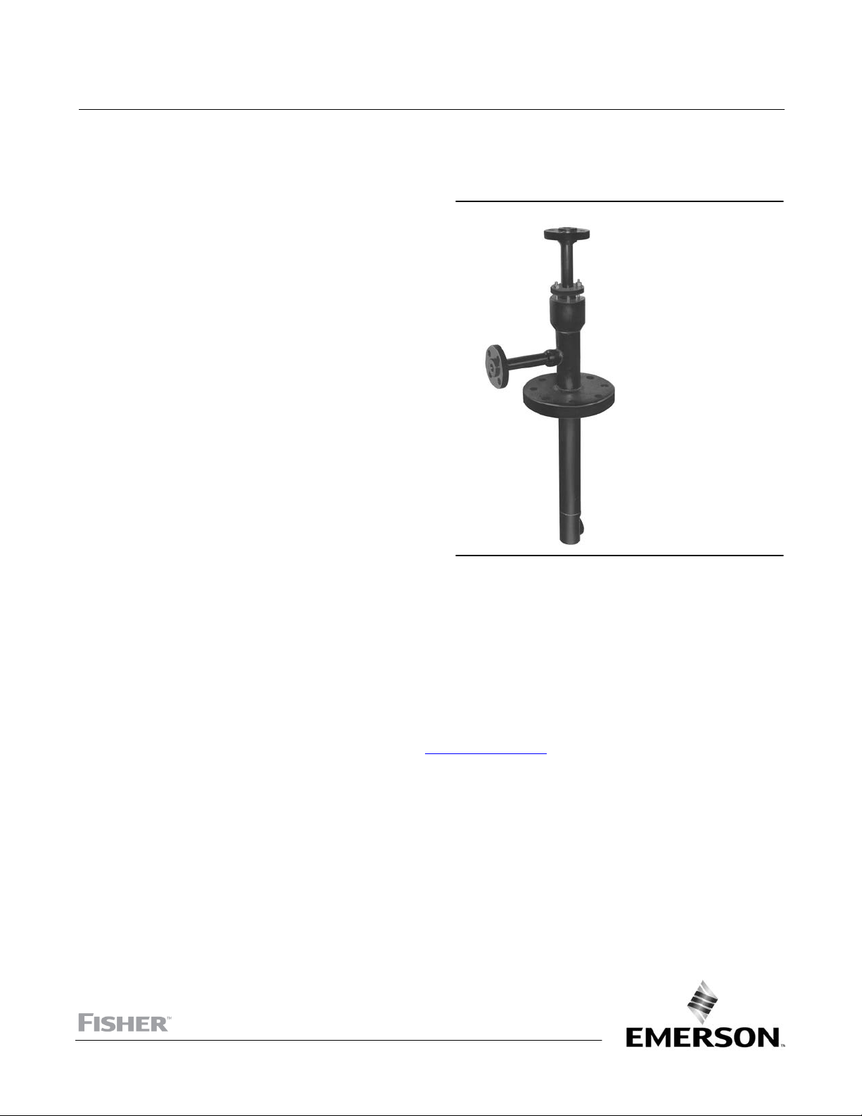
Figure 1. Fisher DSA Steam‐Atomized Desuperheater
W5366‐1
Scope of Manual
This instruction manual includes installation and operation information for the Fisher DSA steam‐atomized
desuperheater.
Do not install, operate, or maintain a DSA desupheater without being fully trained and qualified in valve, actuator, and
accessory installation, operation, and maintenance. To avoid personal injury or property damage, it is important to
carefully read, understand, and follow all the contents of this manual, including all safety cautions and warnings. If you
have any questions about these instructions, contact your Emerson sales office
proceeding.
or Local Business Partner before
Description
The DSA steam‐atomized desuperheater (figure 1) serves a wide range of desuperheating applications. It is best suited
for those installations requiring high rangeability in low steam velocity pipelines. With adequate controls, this unit
provides an efficient means of atomizing spraywater over wide fluctuations in flow rate while maintaining downstream
steam temperature to within 6 to 8_C (10 to 15_F) of saturation. The DSA desuperheater is easily installed directly into
the steam line. The standard mounting is with the desuperheater perpendicular to the steam line. However, the DSA
desuperheater can be made to fit angle or elbow installations.
www.Fisher.com
Page 2

DSA Desuperheater
July 2017
Table 1. Specifications
Instruction Manual
D101618X012
Steam Line Sizes
J NPS 6 to 60
Steam Line Connection Sizes
NPS J 3, J 4, and J 6 J CL150, J CL300,
J CL600, J CL900, J CL1500, and J CL2500
raised‐face flange
Spraywater and Atomizing Steam Connection Sizes
NPS J 1, J 1-1/2, and J 2 J CL150, J CL300,
J CL600, J CL900, J CL1500, and J CL2500
Inherent Rangeability
Up to 50:1
Spraywater Pressure Required
3.5 to 35 bar (50 to 500 psi) greater than steam line
pressure
Minimum Steam Velocity
1.5 m/s (5 feet per second) depending on actual
operating conditions
raised‐face flange
Atomizing Steam
Maximum Inlet Pressures
Consistent with applicable CL150, 300, 600, 900,
1500, or 2500 pressure‐temperature ratings per
ASME B16.34
1. Do not exceed the pressure or temperature limits in this instruction manual, nor any applicable code or standard limitations.
2. Ratio of maximum to minimum controllable Cv.
(1)
Atomizing steam should be at least 2.0 times the
pressure of the steam to be desuperheated. Total
atomizing steam flow (lb/hr) will be 10 to 15 percent
of the maximum spraywater flow (lb/hr).
Principle of Operation
(2)
The DSA desuperheater utilizes the energy of atomizing steam to produce a fine spray of cooling water for injection
into the steam line. An external spraywater control valve controls the quantity of cooling water. The water flows into
the desuperheater and fills the main body of the unit just ahead of the atomizing head. Here the water is directed into
a number of flow channels where it is mixed and atomized by the high velocity atomizing steam (see figure 3).
The atomizing steam is controlled via an automatic or manual shutoff valve. The steam flows down the center of the
desuperheater body toward the atomizing head. Here too, the steam is directed into a number of flow channels. These
channels are sized to produce a critical pressure drop. This assures very high steam velocities and maximum kinetic
energy for spraywater atomization.
The atomizing steam mixes with the cooling water and produces a spraywater cloud with almost infinite surface area.
This spray cloud is almost instantaneously vaporized when injected into the main steam line, resulting in steam at a
reduced temperature.
The atomizing steam tube inside the desuperheater is only secured at the atomizing head. The packing box on top
allows for the free movement of the unit due to thermal expansion from steam/water temperature differentials.
Installation
WARNING
Always wear protective gloves, clothing, and eyewear when performing any installation operations to avoid personal
injury.
2
Page 3

Instruction Manual
D101618X012
Personal injury or equipment damage caused by sudden release of pressure may result if the desuperheater is installed
where service conditions could exceed the limits given in table 1 or on the nameplate. To avoid such injury or damage,
provide a relief valve for over‐pressure protection as required by government or accepted industry codes and good
engineering practices.
Check with your process or safety engineer for any additional measures that must be taken to protect against process
media.
If installing into an existing application, also refer to the WARNING at the beginning of the Maintenance section in this
instruction manual.
DSA Desuperheater
July 2017
CAUTION
When ordered, the desuperheater configuration and construction materials were selected to meet particular pressure,
temperature, pressure drop, and fluid conditions. Do not apply any other conditions to the desuperheater without first
contacting your Emerson Automation Solutions sales office.
1. Insert the DSA desuperheater into the flanged pipe stud on the steam line (see figure 2 for the proper “T” length
dimension). Bolt the unit to the pipe in accordance with standard piping practice.
2. Clean and flush out the cooling water line before connecting to the desuperheater. Use only clean sources of
cooling water. Use of clean water decreases wear to the valve trim and prevents clogging of the desuperheater by
solid particles.
WARNING
Personal injury or property damage could result from clogging of the desuperheater. Emerson Automation Solutions
recommends installation of a strainer and isolating valve on the water line leading to the desuperheater. Failure to do so
may result in clogging of the desuperheater by solid particles, thus hampering temperature control of the steam.
3. A straight run of pipe is required downstream of the desuperheater to assure complete vaporization of cooling
water. Consult the desuperheater certified drawing for the required distance of straight pipe.
4. The temperature sensor should be mounted according to manufacturer's instructions. Minimum distance to the
sensor is approximately 9.1 m (30 feet) downstream of the desuperheater. This distance changes with higher
velocity steam flow and percentage of spraywater required. Consult the desuperheater certified drawing for the
exact distance.
5. Allow no branching out from the steam line, to divide the steam flow, between the temperature sensor and the
desuperheater.
A typical control loop is illustrated in figure 4. A temperature sensor generates a pneumatic instrument air signal
through a transmitter. This signal is transmitted to a remote mounted temperature indicating control station. The
output signal from the control station is sent to the positioner on the spraywater control valve. The positioner output
signal is piped to the actuator, which strokes the valve and controls the flow of cooling water to the desuperheater.
The atomizing steam valve is normally controlled so that it fully opens as soon as the spraywater control valve starts to
open.
WARNING
Personal injury could result from packing leakage. Valve packing was tightened prior to shipment; however some
readjustment will be required to meet specific service conditions.
3
Page 4

DSA Desuperheater
July 2017
Instruction Manual
D101618X012
Operating Instructions
Verification of Control Instrumentation
Note
The following steps assume that a local controller is used. If all controls are through a DCS, adjust verification steps accordingly.
1. Connect the instrument air supply lines to the temperature transmitter, indicating control station, and valve
positioner in accordance with instrumentation manufacturer's instructions.
2. Switch the controller to manual control.
Note
If 0.4 to 2.0 bar (6 to 30 psig) or another range is used, adjust the instrument air signal referenced in the following steps
accordingly.
3. This instruction manual assumes an instrument air signal of 0.2 to 1.0 bar (3 to 15 psig). Adjust the instrument air
signal to 0.2 bar (3 psig). Check that the water valve is completely closed. Adjust the positioner, if necessary.
4. Now adjust the instrument air signal to 1.0 bar (15 psig). Check that the water valve opens to its full travel. Adjust
the positioner to correct the range and re‐zero if needed, by referring to step 3. Check to ensure the atomizing
steam valve opens as soon as the spraywater control valve begins to open.
5. Thereafter, check that the controller is responding so that rising steam temperature gives an increasing instrument
air signal.
6. Adjust the instrument air signal to 0.6 bar (9 psig).
7. Verify that the atomizing steam valve has opened.
8. Open the water supply.
9. Observe the downstream steam temperature.
10. Increase the instrument air signal to 0.8 bar (11 psig). Check that the steam temperature decreases.
11. Adjust the instrument air signal to 0.5 bar (7 psig) and check that the steam temperature rises.
Note
If the temperature does not fall when the instrument air signal is increased, the cause may be that either the water isolation valve
has not been opened or that the steam temperature is close to saturation. If the latter is the case, set the instrument air signal to
0.3 bar (4 psig) [spraywater valve slightly open] and increase to 0.4 bar (6 psig). Check if the temperature decreases.
12. When satisfactory coordination between the instrument air signal and steam temperature is reached, adjust the
controller according to directions of the manufacturer.
13. Switch the controller to ''automatic'' for automatic positioning.
Note
For more detailed calibration information, refer to the instrument manufacturer's operating instructions.
4
Page 5

Instruction Manual
D101618X012
Figure 2. “T” Dimension
DSA Desuperheater
July 2017
D
NPS
6 Nominal
8 Nominal
10 Nominal
12 Nominal
14 Nominal
16 Nominal
18 Nominal
20 Nominal
22 Nominal
24 Nominal
> 24 Nominal
For the NPS 6 mounting flange, add 69.9 mm (2.75 inches) to the “T” dimension.
MOUNTING FLANGE
(ASME RF FLANGE ‐ SAME SIZE & PRESSURE CLASS AS BODY FLANGE)
T
FLOW
D
DIRECTION
A5594
INSTALLATION CONFIGURATION (1 GASKET REQUIRED)
NOTE: ALL FLANGE BOLT HOLES STRADDLE STEAM PIPE CENTERLINE
T
mm Inches
273.1
247.7
215.9
279.4
266.7
241.3
215.9
266.7
241.3
215.9
215.9
10.75
9.75
8.5
11
10.5
9.5
8.5
10.5
9.5
8.5
8.5
Figure 3. Detail of Fisher DSA Desuperheater
ATOMIZING STEAM FLOW
SPRAYWATER
FLOW
ATOMIZING
STEAM
TUBE
ATOMIZING
HEAD
W5371‐1
5
Page 6

DSA Desuperheater
July 2017
Figure 4. Control Loop with Fisher DSA Desuperheater
SV
FISHER 667-EZ
ATOMIZING STEAM
ISOLATION VALVE
Instruction Manual
D101618X012
FISHER 667-EZ
SPRAYWATER
CONTROL VALVE
TC
TC
LS
SPRAYWATER
FISHER 5190
TEMPERATURE
CONTROLLER
ATOMIZING STEAM
B2242‐2
Figure 5. Fisher DSA Assembly
6
12
10 11
13
9
FISHER DSA DESUPERHEATER
STEAM
8
14
4
5
23
1
TE
7
15
B2709
Maintenance Instructions
WARNING
Avoid personal injury from sudden release of process pressure. Before performing any maintenance operations:
D Do not remove the actuator from the desuperheater while the valve is still pressurized.
6
Page 7

Instruction Manual
D101618X012
D Always wear protective gloves, clothing, and eyewear when performing any maintenance operations to avoid personal
injury.
D Disconnect any operating lines providing air pressure, electric power, or a control signal to the actuators. Be sure the
actuators cannot suddenly open or close the atomizing steam or spraywater control valves.
D Completely shut off the process to isolate the DSA desuperheater from process pressure. Relieve process pressure and
drain the process media before servicing the unit.
D Use lock‐out procedures to be sure that the above measures stay in effect while you work on the equipment.
D The desuperheater packing box may contain process fluids that are pressurized, even when the desuperheater has been
removed from the pipeline. Process fluids may spray out under pressure when removing the packing hardware or
packing rings.
D Check with your process or safety engineer for any additional measures that must be taken to protect against process
media.
DSA Desuperheater
July 2017
Servicing
Although the DSA desuperheater is a simple design requiring almost no maintenance, it may be necessary to repack
the unit if a steam packing leak should develop.
WARNING
Residual system pressure may be released during the following steps if the system was improperly isolated or vented. Use
extreme care to prevent personal injury while loosening any fasteners in the pressure boundary.
1. Slowly and evenly loosen the gland nuts (key 13, figure 5) and remove them from the gland studs (key 12, figure 5).
2. Pull back the gland flange (key 10, figure 5) and gland follower (key 9, figure 5) from the stuffing box.
3. Using a suitable packing pick, remove the packing (key 11, figure 5) from the stuffing box.
4. Reinstall packing (key 11, figure 5), making sure to push down each ring as far as possible with the gland follower
(key 9, figure 5) prior to installing the next ring. This process can be made somewhat easier by lubricating each ring
with grease similar to copper‐based anti‐seize or heavy duty anti‐seize.
5. After installation of the new packing set, gland follower and gland flange, tighten the gland nuts (key 13, figure 5)
to seal the packing on the steam pipe from leakage.
6. After ensuring that the DSA desuperheater is properly reinstalled in the pipeline, the unit may be returned to
service. The DSA desuperheater should be monitored as the unit is brought on line to ensure that there are no leaks
in the connections.
Table 1. Troubleshooting Guide
Problem Possible Solution
Temperature setpoint is not reached Check water source availability and pressure
Temperature setpoint is not reached Check nozzle(s) for plugging
Temperature setpoint is not reached Make sure that steam saturation pressure is not above setpoint
Temperature setpoint is not reached Check to ensure full actuator stroke is reached
Temperature is below setpoint Check temperature control loop ‐ reset
Temperature is below setpoint Check nozzle for fouling/poor spray pattern ‐ clean/replace
Temperature is below setpoint Check temperature sensor location ‐ relocate per guidelines
Temperature oscillates around setpoint Tune control system parameters
Temperature oscillates around setpoint Temperature setpoint may be too close to saturation
Water in steam line Check atomizing steam supply pressure and valve opening
Water in steam line Check that steam traps are functioning properly
Water in steam line when steam line isolated Check for leakage of spraywater control valve
Water in steam line Review piping configuration for downstream tees and elbows
7
Page 8

DSA Desuperheater
July 2017
Instruction Manual
D101618X012
Troubleshooting
Table 1 is a basic first line troubleshooting guide. Contact your Emerson sales office or Local Business Partner for
assistance if you are unable to resolve your field operation problem.
Parts Ordering
Each DSA desuperheater is assigned a serial number that can be found on the DSA desuperheater body or on a tag
attached to the mounting flange. Refer to the serial number when contacting your Emerson sales office or Local
Business Partner for technical assistance. When ordering a replacement part, refer to the serial number and key
number. The key numbers in figure 5 can be used to help in part identification.
WARNING
Use only genuine Fisher replacement parts. Components that are not supplied by Emerson Automation Solutions should
not, under any circumstances, be used in any Fisher valve, because they may void your warranty, might adversely affect the
performance of the valve, and could cause personal injury and property damage.
Parts List
Key Description
1 Body Flange
2 Body Pipe
3 Steam Pipe
4 Water Pipe
5 Water Flange
6 Steam Flange
7 Sprat Head
Neither Emerson, Emerson Automation Solutions, nor any of their affiliated entities assumes responsibility for the selection, use or maintenance
of any product. Responsibility for proper selection, use, and maintenance of any product remains solely with the purchaser and end user.
Fisher is a mark owned by one of the companies in the Emerson Automation Solutions business unit of Emerson Electric Co. Emerson Automation Solutions,
Emerson, and the Emerson logo are trademarks and service marks of Emerson Electric Co. All other marks are the property of their respective owners.
The contents of this publication are presented for informational purposes only, and while every effort has been made to ensure their accuracy, they are not
to be construed as warranties or guarantees, express or implied, regarding the products or services described herein or their use or applicability. All sales are
governed by our terms and conditions, which are available upon request. We reserve the right to modify or improve the designs or specifications of such
products at any time without notice.
Emerson Automation Solutions
Marshalltown, Iowa 50158 USA
Sorocaba, 18087 Brazil
Cernay 68700 France
Dubai, United Arab Emirates
Singapore 128461 Singapore
www.Fisher.com
Key Description
8 Stuffing Box
9 Gland Follower
10 Gland Flange
11* Packing
12 Gland Stud
13 Gland Nut
14 Water Sockolet
15 Sprayhead Block
*Recommended spare parts
8
E 1990, 2017 Fisher Controls International LLC. All rights reserved.
 Loading...