

Page 1

Instruction Manual
D104709X012
Fisher™ 8540 Eccentric Disk
Butterfly Control Valve
8540 Valve
September 2021
Contents
Introduction 1.................................
Scope of Manual 1.............................
Description 1.................................
Specifications 2...............................
Installation 2..................................
Valve Orientation 4............................
Maintenance 8.................................
Packing Maintenance 9.........................
Seal Ring Maintenance 11......................
Disk, Drive Shaft and Bearing Maintenance 15......
Actuator Mounting 18.........................
Parts Ordering 19...............................
Parts List 20...................................
Figure 1. Fisher 8540 Butterfly Valve with Bettis RPE
Actuator and 3720 Positioner
X1846
Introduction
Scope of Manual
This instruction manual includes installation, maintenance, and parts information for the 8540 Eccentric Disk Butterfly
Control Valve (see figure 1). Refer to separate instruction manuals for information covering the actuator and
accessories.
Do not install, operate, or maintain 8540 valves without being fully trained and qualified in valve,
actuator, and accessory installation, operation, and maintenance. To avoid personal injury or property
damage, it is important to carefully read, understand, and follow all the contents of this manual,
including all safety cautions and warnings. If you have any questions about these instructions, contact
your Emerson sales office
before proceeding.
Description
The seal design of the 8540 eccentric disk high performance butterfly valve provides excellent shutoff capability. This
valve has a square drive shaft end and soft seal rings for use in a wide variety of applications.
www.Fisher.com
Page 2
8540 Valve
September 2021
Table 1. Specifications
Instruction Manual
D104709X012
Valve Size and End Connection Styles
NPS J 3,J 4,J 6,J 8,J 10, and
Flow Direction
See figure 3
J 12 wafer body valves
Maximum Inlet Pressure
(1)
Carbon Steel and Stainless Steel Valve Bodies:
Consistent with CL150 and 300
pressure/temperature ratings per ASME B16.34
Actuator/Valve Action
With the diaphragm or piston actuators, the valve
action is field‐reversible. Refer to information in the
Installation section.
unless limited by material temperature capabilities.
Shutoff Classifications
J PTFE Seal: Bidirectional shutoff to Class VI per
ANSI/FCI 70‐2 and IEC 60534‐4.
Valve Classification
Face‐to‐face dimensions meet API 609 or MSS‐SP‐68
standards for face‐to‐face dimensions of wafer‐style
valves.
Flow Characteristics
Approximately linear
Shaft Diameters
See table 2
Disk Rotation
Clockwise to close (when viewing from the drive shaft
end) through 90 degrees of disk rotation (see figure
8)
1. The pressure/temperature limits in this manual and any applicable standard or code limitation for valves should not be exceeded.
Approximate Weights
See table 2
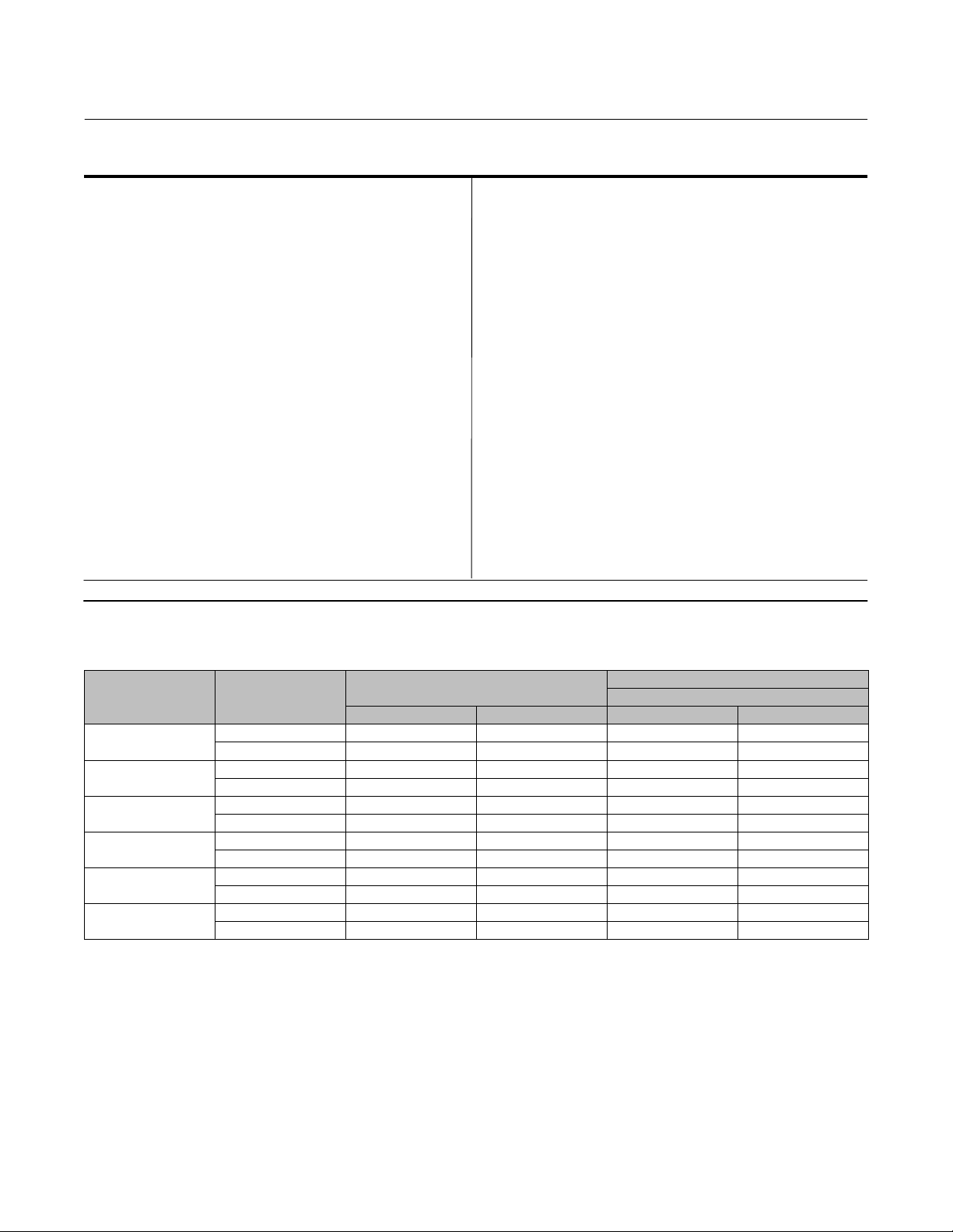
Table 2. Valve Size, Shaft Diameter, and Approximate Weight
APPROXIMATE WEIGHT
Wafer‐Style
VALVE SIZE, NPS CLASS
3
4
6
8
10
12
150 12.7 1/2 4.5 10
300 15.9 5/8 5.9 13
150 15.9 5/8 8.6 19
300 19.1 3/4 10 23
150 19.1 3/4 13 29
300 25.4 1 15 33
150 25.4 1 21 47
300 31.8 1‐1/4 24 53
150 31.8 1‐1/4 34 75
300 38.1 1‐1/2 44 96
150 38.1 1‐1/2 49 107
300 44.5 1‐3/4 64 141
SHAFT DIAMETER
mm Inches kg Pounds
Installation
The valve is normally shipped as part of a control valve assembly, with the power actuator mounted on the valve. If the
valve or actuator have been purchased separately, or if the actuator has been removed for maintenance, mount the
actuator on the valve, and adjust actuator travel before inserting the valve body into the line. This is necessary due to
the measurements that must be made during the actuator calibration adjustment process. Refer to the Actuator
Mounting section of this manual to mount the actuator on the valve. Refer to the actuator instruction manual for
mounting and adjusting instructions before proceeding.
2
Page 3
Instruction Manual
D104709X012
8540 Valve
September 2021
WARNING
Always wear protective gloves, clothing, and eyewear when performing any installation operations to avoid personal
injury.
To avoid personal injury or property damage resulting from the sudden release of pressure, do not install the valve
assembly where service conditions could exceed the limits given in this manual, the limits on the appropriate nameplates,
or the matching pipe flange rating. Use pressure‐relieving devices as required by government or accepted industry codes
and good engineering practices.
Check with your process or safety engineer for any additional measures that must be taken to protect against process
media.
If installing into an existing application, also refer to the WARNING at the beginning of the Maintenance section in this
instruction manual.
WARNING
When ordered, the valve configuration and construction materials were selected to meet particular pressure, temperature,
pressure drop, and controlled fluid conditions. Responsibility for the safety of process media and compatibility of valve
materials with process media rests solely with the purchaser and end-user. To avoid possible personal injury and because
some valve/trim material combinations are limited in their pressure drop and temperature ranges, do not apply any other
conditions to the valve without first contacting your Emerson sales office
.
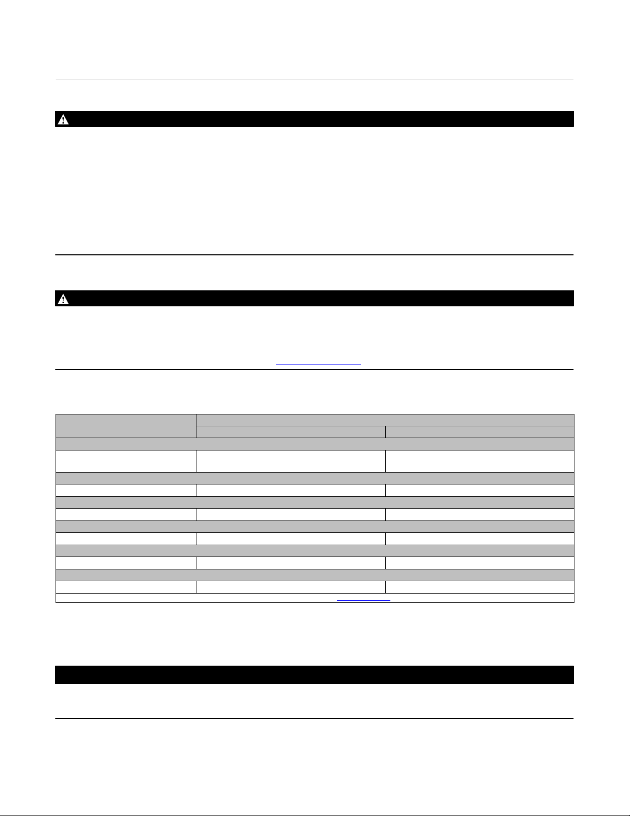
Table 3. Construction Material Temperature Limits
COMPONENTS AND MATERIALS OF
CONSTRUCTION
Valve Body Material
Carbon Steel
CF8M
Disk Material
CF8M -198 to 538 -325 to 1000
Shaft Material
S17400 -62 to 427 -80 to 800
Bearing Material
PEEK / PTFE lined -46 to 232 -50 to 450
Packing Material
PTFE V-Rings -46 to 232 -50 to 450
Seal Ring
PTFE (standard) Soft Seal Ring -46 to 232 -50 to 450
1. Refer to Ordering Matrix for 8540 Valves. For selection temperatures not shown above, contact your Emerson sales office.
(1)
TEMPERATURE LIMITS
_C _F
-29 to 427
-198 to 538
-20 to 800
-325 to 1000
1. Install a three‐valve bypass around the control valve assembly if continuous operation is necessary during
inspection and maintenance of the valve.
2. Inspect the valve to be certain that it is free of foreign material.
CAUTION
Be certain that adjacent pipelines are free of any foreign material, such as pipe scale or welding slag, that could damage the
valve sealing surfaces.
3
Page 4
8540 Valve
September 2021
Instruction Manual
Table 4. Maximum Allowable Pressure Drops at Temperature
TEMPERATURE PRESSURE DROP
5C 5F bar psi
-46 -50
-32 -25
-18 0
38 100
66 150
93 200 43 620
121 250 35 510
149 300 27 390
204 400 11 160
232 450 3 50
52 750
Valve Orientation
When installing the valve, it is recommended that the valve drive shaft be horizontal as shown in figure 1.
D104709X012
Valve Direction
The high performance butterfly valve is designed to allow flow in either direction when in the open position. When in
the closed position, high pressure should be applied to a specific side of the disk to provide best performance and
optimal valve life (see seal types below). See figure 2.
The PTFE soft seal is bi‐directional under normal operating conditions can (at different times) experience pressure in
both directions; the highest of the two pressures should be exerted on the preferred side of the disk. If the two
pressures are equal, then the one lasting the longest period of time should be applied to the preferred side.
1. For PTFE seal ring: This seal is bidirectional. For optimal performance, high pressure should be applied to the front
(retaining ring side) of the disk.
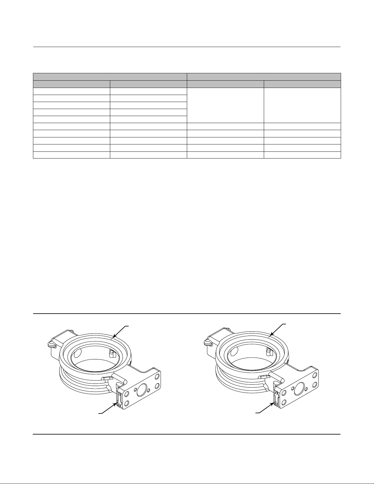
Figure 2. Flow Direction Arrow
RETAINER RING SIDE
RETAINER RING SIDE
FLOW ARROW
4
FORWARD FLOW
FLOW ARROW
REVERSE FLOW
Page 5
Instruction Manual
D104709X012
Figure 3. Flow Direction
RETAINER RING
FORWARD
FLOW
8540 Valve
September 2021
REVERSE
FLOW
FACE SIDE OF DISK
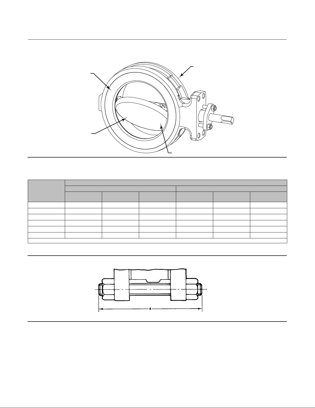
Table 5. Stud Bolt Data
VALVE SIZE, NPS
3 4 5/8‐11 5.75 8 3/4‐10 6.5
4 8 5/8‐11 6 8 3/4‐10 7
6 8 3/4‐10 6.5 12 3/4‐10 7.5
8 8 3/4‐10 7 12 7/8‐9 9
10 12 7/8‐9 8 16 1‐8 10
12 12 7/8‐9 8.5 16 1‐1/8‐8 11
1. Thread engagement in accordance with ASME B31.3.
(1)
No. of Stud Bolts
WAFER STYLE
CL150 CL300
Size Dia
Inch & Thread
A Dimension, Inch No. of Stud Bolts
Size Dia
Inch & Thread
Figure 4. Stud Bolts for Installation (also see table 5)
A3887
STUD BOLT
A Dimension, Inch
5
Page 6
8540 Valve
September 2021
Instruction Manual
D104709X012
Installing the Valve in the Pipeline
WARNING
The edges of a rotating disk have a shearing effect that may result in personal injury. To help prevent such injury, stay clear
of the disk edges when rotating the disk (key 3, figure 12).
CAUTION
Damage to the disk will occur if any pipe flanges or piping connected to the valve interfere with the disk rotation path. If
the piping flange has a smaller inner diameter than what is specified for schedule 80 piping, measure carefully to be certain
the disk rotates without interference before putting the valve into operation.
CAUTION
Damage to the disk (key 3) sealing surfaces may occur if the disk is not closed when the valve is being installed or removed
from the pipeline. If necessary, use a temporary pressure source on the actuator to retain the disk in the closed position
while installing or removing the valve from the pipeline.
1. For Fail‐Open Actuators: It will be necessary to provide a temporary loading pressure to the actuator diaphragm to
move the valve disk to the closed position. Observe the above Warning when closing the valve. If a loading pressure
is required, use caution when working with the valve. If the loading pressure is disconnected, the disk will open
rapidly.
2. With the disk in the closed position, install line flange gaskets, and install the valve between the pipeline flanges.
Note
The wafer style valves use the standard size spiral wound gaskets.
Select the appropriate gaskets for the application. Gasket types made to ASME 16.5 group or a user's standards can be
used for 8540 valves depending on the service conditions and applications.
3. Install the flange studs:
Note
Lubricate line flange studs or bolts before inserting them into flanges. If necessary, provide additional support for the control valve
assembly because of its combined weight.
D Flange studs: Install two or more line flange studs into the line flanges to help hold the valve in position while
centering the valve. Carefully center the valve on the flanges to ensure disk clearance.
6
Page 7
Instruction Manual
D104709X012
8540 Valve
September 2021
D Select and install two pipe line gaskets.
4. Install the remaining line flange bolting to secure the valve in the pipeline. Tighten the nuts to the line flange studs
in a crisscross pattern to ensure proper alignment of valve, gaskets, and flanges.
Packing Adjustment and Shaft Bonding
WARNING
Personal injury could result from packing leakage. Valve packing was tightened before shipment; however the packing
might require some readjustment to meet specific service conditions. Check with your process or safety engineer for any
additional measures that must be taken to protect against process media.
CAUTION
Use caution when tightening packing follower nuts because over‐tightening the nuts will accelerate wear and could
produce higher rotating friction loads on the valve stem.
D PTFE packing: tighten standard packing follower nuts only enough to prevent shaft leakage. Excessive tightening of
packing will accelerate wear and could produce higher rotating friction loads on the valve stem. If necessary, refer
to the Packing Maintenance section.
WARNING
The valve drive shaft is not necessarily grounded to the pipeline when installed. Personal injury or property damage could
result from an explosion caused by a discharge of static electricity from the valve components if the process fluid or the
atmosphere around the valve is flammable. To avoid personal injury or property damage, make sure the valve is grounded
to the pipeline before placing the valve assembly into service.
Standard PTFE packing is composed of a partially conductive carbon‐filled PTFE female adaptor with PTFE V‐ring packing.
Alternate shaft‐to‐valve body bonding is available for hazardous service areas where the standard packing is not sufficient
to bond the shaft to the valve (see the following step).
1. Attach the bonding strap assembly (key 131, figure 5) to the shaft with the clamp (key 130, figure 5), and connect
the other end of the bonding strap assembly to the valve with the cap screw (key 14, figure 5).
2. For more information, refer to the Packing Maintenance subsection below.
7
Page 8

8540 Valve
September 2021
Figure 5. Optional Shaft-to-Valve Body Bonding Strap Assembly
VALVE BODY
Instruction Manual
D104709X012
ACTUATOR MOUNTING BRACKET
A
GH14001
VIEW A-A
A
Maintenance
Valve parts are subject to normal wear and must be inspected and replaced as necessary. The frequency of inspection
and replacement depends upon the severity of service conditions. Instructions are given in this section for replacing
packing, seal ring, disk, shaft, bearings, and other valve parts. Also, instructions are provided for changing valve action,
mounting, and adjusting the actuator. Refer to the actuator instruction manual for additional information for
mounting and adjusting the actuator.
WARNING
Avoid personal injury or property damage from sudden release of process pressure or bursting of parts. Before performing
any maintenance operations:
D Do not remove the actuator from the valve while the valve is still pressurized.
D Always wear protective gloves, clothing, and eyewear when performing any maintenance operations to avoid personal
injury.
D Disconnect any operating lines providing air pressure, electric power, or a control signal to the actuator. Be sure the
actuator cannot suddenly open or close the valve.
D Use bypass valves or completely shut off the process to isolate the valve from process pressure. Relieve process pressure
from both sides of the valve. Drain the process media from both sides of the valve.
D Vent the pneumatic actuator loading pressure and relieve any actuator spring precompression.
D Use lock‐out procedures to be sure that the above measures stay in effect while you work on the equipment.
D The valve packing box may contain process fluids that are pressurized, even when the valve has been removed from the
pipeline. Process fluids may spray out under pressure when removing the packing hardware or packing rings, or when
loosening the packing box pipe plug.
D Check with your process or safety engineer for any additional measures that must be taken to protect against process
media.
D It is possible to damage the valve if the actuator travel stops are not properly adjusted before stroking the valve.
8
Page 9

Instruction Manual
D104709X012
8540 Valve
September 2021
CAUTION
During any of the following steps, do not rotate the disk past 90 degrees in the open direction. Rotating the disk past 90
degrees can damage the seal ring.
Packing Maintenance
PTFE‐filled packing has a partially conductive packing ring (such as a carbon‐filled PTFE female adaptor) to electrically
bond the shaft to the valve body.
When replacing the packing, it is recommended to remove the control valve assembly from the pipeline because
valve/actuator adjustments must be made with the valve out of the pipeline.
Disassembly
Key numbers and part locations are shown in figure 12 unless otherwise noted.
1. Isolate the control valve from the line pressure, release pressure from both sides of the valve body, and drain the
process media from both sides of the valve. If using a power actuator, also shutoff all pressure lines to the power
actuator, release all pressure from the actuator. Use lock‐out procedures to be sure the above measures stay in
effect while you work on the equipment.
2. Note the position of the mark on the end of the valve shaft, and its relationship to the actuator shaft.
3. Remove the actuator per instructions in separate actuator instruction manuals, then remove the cap screws (key
14, figure 5). Remove the clamp if the strap is used.
4. Remove the packing nuts (key 101) and packing follower (key 114). For NPS12 CL300, remove the packing flange
and follower (key 102 and 114).
5. Remove the old packing rings, using a formed hook.
CAUTION
Carefully use the hook. Avoid damaging the drive shaft or packing box wall. Scratches on valve surfaces can cause leakage.
(Note: The packing box ring (key 107) can remain in place when replacing packing only.)
6. Clean all accessible metal parts and surfaces to remove particles that would prevent the packing from sealing.
Assembly
Inspect the shaft: If it is damaged, it cannot make a good seal with the packing, and it must be replaced. If the leakage
comes from the outside diameter of the packing, it is possible that the leakage is caused by nicks or scratches around
the packing box wall. Inspect the packing box wall for nicks and scratches when performing the following procedures.
9
Page 10

8540 Valve
September 2021
Figure 6. Typical Packing Arrangement
C0785*A
Instruction Manual
D104709X012
PACKING
FOLLOWER
PACKING SET
PACKING BOX
RING
PTFE V-RING PACKING
10
Page 11

Instruction Manual
D104709X012
8540 Valve
September 2021
1. Install the new packing parts (see figure 6). Install the packing follower and finger tighten the packing flange nuts
onto the studs only enough to stop leakage.
2. If the valve was equipped with a bonding strap assembly (figure 5), re‐install the assembly.
3. Refer to the Actuator Mounting section of this manual. If necessary, refer to the separate actuator instruction
manual for adjustment procedures.
4. When the control valve is being placed into operation, check around the packing follower for leakage.
Leakage from the PTFE packing can often be stopped by tightening the packing flange nuts just enough to stop the
leak.
CAUTION
Use caution when tightening the nuts. Overtightening the nuts can damage packing box parts and result in increased drive
shaft friction.
Seal Ring Maintenance
Perform this procedure if the control valve is not shutting‐off properly (if it is leaking downstream). It is recommended,
but not required, to remove the actuator for easier handling of the valve during the following procedures.
WARNING
The edges of a rotating disk close with a shearing effect that may result in personal injury. To help prevent such injury, stay
clear of the disk edges when rotating the disk (key 3).
CAUTION
During any of the following steps, do not rotate the disk past 90 degrees in the open direction. Rotating the disk past 90
degrees can damage the seal ring.
Figure 7. Retainer Ring Knock‐Out Flat
FLAT END PUNCH
KNOCK-OUT FLAT
11
Page 12

8540 Valve
September 2021
Key numbers are shown in figure 12 unless otherwise noted.
Instruction Manual
D104709X012
Disassembly
Most maintenance procedures will require the actuator to be removed.
1. Isolate the control valve from line pressure, and relieve pressure from the valve body. Shut off and disconnect all
lines from the power actuator.
2. Be sure the disk is in the closed position before attempting to remove the valve from the pipeline or flanges
D For Fail‐Open Actuators: It will be necessary to provide a temporary loading pressure to the actuator diaphragm to
move the valve disk to the closed position. Observe the above Warning when closing the valve. If a loading pressure
is required, use caution when working with the valve. If the loading pressure is disconnected, the disk will open
rapidly.
3. With the disk in the closed position, remove line bolting, then remove the control valve assembly from the pipeline.
4.
Remove the actuator as described in the Packing Maintenance section.
5. Remove the retainer ring (key 2, figure 8):
D Place the valve on blocks with the seal retainer facing down. (Note: Position blocks so they do not restrict the
retainer ring removal.)
.
D Rotate the disk to the open position as shown in figure 7.
D Locate one of the knock‐out points machined on the retainer ring. Using a hammer and flat end punch the
knock‐out point, pop out the retainer ring from the valve body.
CAUTION
When popping out the retainer ring, be very careful to hit only the knock‐out points. Hitting anywhere else can cause
non‐repairable damage to the t‐slot area.
D Clean all sealing surfaces and parts before re‐assembly.
6. Remove the seal ring from the valve body seal ring slot. Remove the spring from the PTFE seal ring (key 5) as it may
be necessary to re‐install the spring into the new PTFE seal ring.
7. If it is necessary to replace the disk, drive shaft, and the bearings, refer to that section below before proceeding with
the assembly procedures for the seal ring and retainer. The seal ring could be damaged if it is in place while
removing the disk.
Assembly
Place the valve on blocks with the seal retainer facing up. If the replacement disk, shaft, and bearings have not been
installed in the valve body, go to the proper assembly procedures to install them.
CAUTION
Do not install the seal ring without the disk being in place. The seal ring could be damaged while installing the disk.
12
Page 13

Instruction Manual
D104709X012
Figure 8. Disk Rotation Indication
8540 Valve
September 2021
DISK STOP
TO OPEN
NOTE:
1
SET ACTUATOR TRAVEL STOPS TO OBTAIN AN
EQUAL DISTANCE TO DISK SURFACE AS SHOWN.
DISK IN THE
CLOSED POSITION
ACTUATOR
END OF SHAFT
DISK POSITION
INDICATOR
RETAINER
RING
DISK IN THE
OPEN POSITION
CAUTION
Do not rotate the disk past 90 degrees in the open direction. Rotating the disk past 90 degrees can damage the seal ring or
other component parts.
Note
PTFE, NOVEX, and Phoenix Ill seal rings used in other valve types are not interchangeable with seal rings used in the 8540 valve.
The 8540 seal rings are not interchangeable with seal rings in any other valve type. To order seal rings for this valve, provide the
serial number on the valve.
1. Installing PTFE seal rings:
a. The valve disk should be open while installing the seal ring. If not, rotate the disk to the open position as shown in
figure 8.
b. Hook the spring ends together, insert the spring (see figure 9) into the groove in the seal ring, and work the
spring into the recess in the PTFE seal ring.
13
Page 14

8540 Valve
September 2021
Instruction Manual
D104709X012
c. Install the seal ring assembly into the slot in the valve body as shown in figure 9. Refer to Installing the retainer
ring steps below.
Figure 9. Available Seal Configurations
RETAINING
RING
SPRING
PRESSURE‐
ASSISTED SEAL
HIGH
PRESSURE
SHUTOFF
DISK FACE
PTFE SEAL
VALVE
BODY
SEAL
RING
2. Installing the retainer ring:
a. Wipe excessive oil off the retainer ring outside diameter, and off the retainer counterbore in the valve body.
b. Rotate the disk to the open position.
c. Lay the retainer ring on the valve body.
d. Use a press, or a soft‐faced hammer to press the retainer ring into its groove in the valve body.
CAUTION
It takes a considerable amount of force with a hammer to drive the retainer ring into place. Be sure not to damage retainer
ring surfaces when installing the ring.
e. The retainer ring is properly seated when the face of the retainer ring is flush with the face of the valve body.
f. To ensure proper seal performance for metal seals, you may need to use the hammer to drive the disk open for
the first few times. When closing the valve, use the C‐clamps discussed in the next few steps.
CAUTION
Do not damage the gasket seating surfaces on either the valve body or the retainer ring when installing or removing the
C‐clamps. Protect the gasket surface by using a soft material between the clamp and valve body/retaining ring serrations
to avoid damage.
g. Use three C‐clamps to hold the retainer in place. Locate one of the C‐clamps near the travel stop in the valve
body, and the other two at 120 degrees from the stop.
h. When cycling the disk for the first three times, use a dead‐blow hammer with a soft head to drive the disk closed.
Also, you may need to use the hammer to drive the disk open for the first few times.
14
Page 15

Instruction Manual
D104709X012
3. Turn the disk into and out of the seal ring several times, to help break in the seal and reduce actuator torque
requirements during adjustment.
4. If replacing the packing, remove all packing parts from the valve body. Upon re‐assembly of the valve, refer to the
Packing Maintenance procedures to replace the packing.
8540 Valve
September 2021
Disk, Drive Shaft, and Bearing Maintenance
This procedure is to be performed when replacing the valve disk, drive shaft, taper pins, hollow pins, and bearings due
to wear or damage to one or more component parts.
Key numbers are shown in figure 12 unless otherwise noted.
Disassembly
1. Isolate control valve from line pressure, relieve pressure and drain process fluid, then remove control valve
assembly from the pipeline as described in Seal Ring Maintenance section.
2. Loosen the packing flange nuts (key 101). This allows the drive shaft (key 8) to turn without the friction caused by
the packing.
3. Remove the actuator using the steps provided in the Packing Maintenance section and separate actuator
instruction manuals, and remove the seal ring using the steps provided in the seal ring maintenance procedures
above.
4. Place the valve on a flat working surface with the seal ring slot facing down
5. Use blocks to raise the valve body high enough to allow the disk to be rotated to the fully open position (see figure
8).
6. Rotate the disk (key 3) to the fully open position.
7. Locate the small ends of the taper pins. Drive the two taper pins (key 10) out towards the larger end of the pins.
(Note: Attempting to drive the taper pins in the opposite direction only tightens the pins.) Also, remove the hollow
pins (key 9) from the disk/shaft connection using the tool shown in figure 11.
.
Note
Make the tools for removal and installation of the hollow pin shown in figure 11.
8. Unscrew and remove the packing flange nuts (key 101), and the packing flange (key 102).
WARNING
Once the shaft has been removed in the following step, the disk may fall out of the valve body cavity. To avoid personal
injury and property damage, support the disk to prevent it from falling as the shaft is being removed.
9. Pull the shaft out of the valve body, and remove the disk (key 3) from the valve body bore.
10. If the packing is to be replaced, remove all the packing parts from the valve body. Upon re‐assembly of the valve,
refer to the Packing Maintenance procedures to replace the packing parts.
11. Remove both of the bearings (key 6) from the valve body.
12. Clean all the sealing surfaces and parts, and inspect and/or obtain replacements before assembly.
Assembly
1. Install the bearings (key 6):
15
Page 16

8540 Valve
September 2021
Instruction Manual
D104709X012
When installing the bearings in the opposite side of the valve body bore, repeat the following procedures.
D Position the bearing edge to match the valve body bore, and insert the one piece bearing/disk spacer into the
bearing bore with the bearing tab facing away from the disk stop as shown in figure 10.
CAUTION
To avoid product damage, protect the disk sealing surfaces while inserting the disk into the valve body bore.
2. Position the disk to be certain that the holes in the disk are towards the actuator side of the valve. Carefully insert
the disk into the valve body bore while protecting the disk sealing surfaces. Install the shaft (key 8):
3. Slide the shaft through the valve body bore and bearing. Position the disk as stated above and slide the shaft
through the disk and outer bearing. Refer to step 4 below.
Installing the hollow pin and taper pin
4. Place the valve body on a flat working surface with the slot for the seal ring facing up. Block the valve body high
enough to allow the disk to be rotated into the open position as shown in figure 11.
Figure 10. Orientation of Bearing/Spacer Tab
CENTER LINE OF SHAFT BORE CENTER L.INE OF BODY AND DISK SPACER
A6357-1
DISK STOP
BEARING TAB OR DISK SPACER TAB
5. Rotate the disk to the open position. On the end of the drive shaft, locate the disk position mark on the end of the
drive shaft. Rotate the shaft until it is in the appropriate disk position as shown in figure 11.
Note
Make sure the taper and hollow pins are free of particulate matter before continuing.
6. Line‐up both holes in the disk hub with the holes in the drive shaft (key 8). (Note: The hole in the drive shaft is offset
to prevent the shaft from being installed in the wrong position. Be sure the hole in the shaft is lined up with the hole
in the disk hub.)
7. Insert the hollow pins (key 9), into the disk hub as shown in figure 11.
Using the tool shown in figure 11, tap the hollow pin down into the disk hub and shaft until the hollow pin bottoms on
the stop in the disk.
8. Insert the taper pins (key 10) into the hollow pins. Using a flat end punch, drive the taper pins into the hollow pins
until solid contact is felt. Anchor the pins in place by staking them with a center‐punch and hammer. The disk and
shaft should rotate smoothly.
9. Install the seal ring assembly using the appropriate instructions in the Seal Ring Maintenance procedures.
16
Page 17

Instruction Manual
D104709X012
8540 Valve
September 2021
10. Install the packing parts using the appropriate instructions provided in the Packing Maintenance procedures. Refer
to the Actuator Mounting procedures before installing the valve in the pipeline.
Table 6. Removal Tool Dimensions
SHAFT DIAMETER jA B C jD
mm
12.7 3.91 28.43 6.35 4.19
15.88 4.60 38.10 7.87 23.37
19.05 5.13 44.45 9.65 5.41
25.4 7.00 59.44 12.70 7.26
31.75 9.50 76.20 19.05 9.78
38.1 10.82 88.90 19.05 11.10
44.45 12.37 114.30 22.35 12.65
Inch
1/2 0.154 1.12 0.25 0.165
5/8 0.181 1.50 0.31 0.192
3/4 0.202 1.75 0.36 0.213
1 0.275 2.34 0.50 0.286
1‐1/4 0.374 3.00 0.75 0.385
1‐1/2 0.426 3.50 0.75 0.437
1‐3/4 0.487 4.50 0.88 0.498
Table 7. Installation Tool Dimensions
SHAFT DIAMETER jA jB jC D E
mm
12.7 12.7 3.68 6.35 127.0 4.83
15.88 12.7 4.57 7.62 127.0 4.83
19.05 12.7 5.23 8.89 127.0 4.83
25.4 12.7 7.00 10.41 127.0 4.83
31.75 19.05 10.00 13.59 146.0 6.35
38.1 19.05 11.56 15.24 146.0 6.35
44.45 19.05 31.21 16.76 146.0 6.35
Inch
1/2 0.50 0.145 0.250 5.00 0.19
5/8 0.50 0.180 0.300 5.00 0.19
3/4 0.50 0.206 0.350 5.00 0.19
1 0.50 0.275 0.410 5.00 0.19
1‐1/4 0.75 0.395 0.535 5.75 0.25
1‐1/2 0.75 0.455 0.600 5.75 0.25
1‐3/4 0.75 0.520 0.660 5.75 0.25
17
Page 18

8540 Valve
September 2021
Figure 11. Taper Pin and Hallow Pin Removal and Installation
B
C
jA
0.03 x 455
jA
0.06 x 455
Instruction Manual
D104709X012
D
E
155
jC
jB
INSTALLATION TOOL
0.01 x 455
REMOVAL TOOL
INSTALLATION
TOOL
VALVE DISK
NOTE:
1
REMOVE THE HOLLOW PIN FROM THIS SIDE OF THE DISK HUB.
0.010 UNDERCUT PER SIDE
DISK HUB
REMOVAL TOOL
HOLLOW PIN
TAPER PIN AND HOLLOW PIN LOCATIONS
Actuator Mounting
Re‐install the seal ring and packing rings using the appropriate procedures before installing the actuator on the valve.
Mount the actuator on the valve body in accordance with the instructions in the actuator instruction manual and this
section.
In the Packing Maintenance steps, you should have noted the position of the mark on the end of the valve shaft, and its
relationship to the actuator shaft. If not, determine the configuration needed to match your application.
Be certain that the disk is rotating counterclockwise to open when viewed from the actuator side of the valve, and that
the disk is not rotated beyond its limits.
1. Orientate the valve drive shaft correctly to match the actuator or handlever position, and install it into the actuator
and actuator lever arm until the mounting pads mate with each other.
2. Tighten the actuator‐mounting cap screws to the appropriate bolt torque from table 8.
CAUTION
The valve disk stop, in the valve body bore is not to be used as a power actuator travel stop (see figure 10). Use the actuator
travel stops to limit the rotation of the valve disk. It is possible to damage the valve component parts if full actuator thrust
is applied to the valve disk stop.
For actuators with an adjustable travel stop, the travel stop must be adjusted so that the valve is closed (determined by
measuring as shown in figure 7) when the diaphragm or piston is against the actuator at the travel stop.
For manually operated actuators or actuators without adjustable linkage, make certain that the travel of the actuator stops
before the disk rotates past the closed position.
18
Page 19

Instruction Manual
D104709X012
8540 Valve
September 2021
Table 8. Recommended Bolt Torques for Actuator/Mounting Cap Screws and Nuts
RECOMMENDED BOLT TORQUE
VALVE SIZE, NPS
3, 4, 6, and 8 88 65
10 and 12 135 100
3, 4, and 6 88 65
8 and 10 135 100
12 183 135
Note
To obtain proper shutoff, the closed position of the 8540 valves must be set with the disk parallel to the retaining ring. Do not use
the disk stop to set the actuator travel stops.
Nwm lbwft
CL150
CL300
3. Adjust the actuator travel stop to limit the open and closed positions of the valve disk. (If necessary, refer to the
actuator instruction manual for more information about adjustments.) Do not use the disk stop as a actuator travel
stop as discussed in the Caution above.
4. For actuators with adjustable turnbuckles, adjust the turnbuckle to bring the disk to the fully closed position at the
end of the actuator stroke. If necessary, refer to the appropriate actuator instruction manual for assistance.
5. If using a manual handwheel or handlever actuator, refer to the appropriate actuator instruction manual for
mounting positions and adjustments.
6. To determine the fully closed disk position (zero degrees of disk rotation), measure the distances between the
positions on the disk face as shown in figure 8. Use the actuator to rotate the disk while re‐checking the two
measurements. Repeat adjustment until the two measurements are equal.
Parts Ordering
When corresponding with your Emerson sales office about this equipment, always mention the valve serial number.
WARNING
Use only genuine Fisher replacement parts. Components that are not supplied by Emerson should not, under any
circumstances, be used in any Fisher valve, because they may void your warranty, might adversely affect the performance
of the valve, and could cause personal injury and property damage.
19
Page 20

8540 Valve
September 2021
Instruction Manual
D104709X012
Parts List
Note
For part ordering information contact your Emerson sales office
Key Description
1 Valve Body
If you need a new valve body, order by valve
size, serial number and desired material.
2* Seal Retainer
3 Valve Disk
4* Seal Ring
5* Spring
6* Bearing (2 req'd)
8* Drive Shaft
9* Hollow Pin
10* Taper Pin
18 Mfg Label
19 Drive Screw, w/ nameplate
21 Nameplate
.
22 Lead Seal & Wire (not shown)
23 Bottom Cap, 12‐inch only
24 Bottom Cap Stud, 12‐inch only
25 Bottom Cap Hex Nut, 12‐inch only
27 Bottom Cap Gasket, 12‐inch only
29 Flow Arrow
100 Packing Stud (2 req'd)
101 Packing Nut (2 req'd)
102 Packing Flange
105* Packing Set
107 Packing Box Ring
108* Packing Ring (4 req'd)
111 Tag
114 Packing Follower
115* Packing Washer (3 req'd)
20
*Recommended spare parts
Page 21

Instruction Manual
D104709X012
Figure 12. Fisher 8540 Valve Assembly
8540 Valve
September 2021
PTFE PACKING
34B5064
NOTE:
KEYS 21, 22, 28, AND 115 ARE NOT SHOWN.
GH13521
NPS 12
CL300
TWO-PIECE FOLLOWER
VIEW B
PTFE SEAL
VIEW B
21
Page 22

8540 Valve
September 2021
Instruction Manual
D104709X012
22
Page 23

Instruction Manual
D104709X012
8540 Valve
September 2021
23
Page 24

8540 Valve
September 2021
Instruction Manual
D104709X012
Fisher is a mark owned by one of the companies in the Emerson Automation Solutions business division of Emerson Electric Co. Emerson Automation
Solutions, Emerson, and the Emerson logo are trademarks and service marks of Emerson Electric Co. All other marks are the property of their respective
owners.
The contents of this publication are presented for informational purposes only, and while every effort has been made to ensure their accuracy, they are not
to be construed as warranties or guarantees, express or implied, regarding the products or services described herein or their use or applicability. All sales are
governed by our terms and conditions, which are available upon request. We reserve the right to modify or improve the designs or specifications of such
products at any time without notice. Neither Emerson, Emerson Automation Solutions, nor any of their affiliated entities assumes responsibility for the
selection, use or maintenance of any product. Responsibility for proper selection, use, and maintenance of any product remains solely with the purchaser
and end user.
Emerson Automation Solutions
Marshalltown, Iowa 50158 USA
Sorocaba, 18087 Brazil
Cernay 68700 France
Dubai, United Arab Emirates
Singapore 128461 Singapore
www.Fisher.com
24
E 2021 Fisher Controls International LLC. All rights reserved.
 Loading...